EP0252856B1 - Dispositif et procédé d'optimisation de la combustion dans les fours à chambres pour la cuisson de blocs carbones - Google Patents
Dispositif et procédé d'optimisation de la combustion dans les fours à chambres pour la cuisson de blocs carbones Download PDFInfo
- Publication number
- EP0252856B1 EP0252856B1 EP87420153A EP87420153A EP0252856B1 EP 0252856 B1 EP0252856 B1 EP 0252856B1 EP 87420153 A EP87420153 A EP 87420153A EP 87420153 A EP87420153 A EP 87420153A EP 0252856 B1 EP0252856 B1 EP 0252856B1
- Authority
- EP
- European Patent Office
- Prior art keywords
- opacity
- temperature
- depression
- combustion
- gases
- Prior art date
- Legal status (The legal status is an assumption and is not a legal conclusion. Google has not performed a legal analysis and makes no representation as to the accuracy of the status listed.)
- Expired
Links
Images


Classifications
-
- F—MECHANICAL ENGINEERING; LIGHTING; HEATING; WEAPONS; BLASTING
- F27—FURNACES; KILNS; OVENS; RETORTS
- F27B—FURNACES, KILNS, OVENS, OR RETORTS IN GENERAL; OPEN SINTERING OR LIKE APPARATUS
- F27B13/00—Furnaces with both stationary charge and progression of heating, e.g. of ring type, of type in which segmental kiln moves over stationary charge
- F27B13/02—Furnaces with both stationary charge and progression of heating, e.g. of ring type, of type in which segmental kiln moves over stationary charge of multiple-chamber type with permanent partitions; Combinations of furnaces
-
- F—MECHANICAL ENGINEERING; LIGHTING; HEATING; WEAPONS; BLASTING
- F23—COMBUSTION APPARATUS; COMBUSTION PROCESSES
- F23N—REGULATING OR CONTROLLING COMBUSTION
- F23N5/00—Systems for controlling combustion
- F23N5/003—Systems for controlling combustion using detectors sensitive to combustion gas properties
-
- Y—GENERAL TAGGING OF NEW TECHNOLOGICAL DEVELOPMENTS; GENERAL TAGGING OF CROSS-SECTIONAL TECHNOLOGIES SPANNING OVER SEVERAL SECTIONS OF THE IPC; TECHNICAL SUBJECTS COVERED BY FORMER USPC CROSS-REFERENCE ART COLLECTIONS [XRACs] AND DIGESTS
- Y02—TECHNOLOGIES OR APPLICATIONS FOR MITIGATION OR ADAPTATION AGAINST CLIMATE CHANGE
- Y02P—CLIMATE CHANGE MITIGATION TECHNOLOGIES IN THE PRODUCTION OR PROCESSING OF GOODS
- Y02P10/00—Technologies related to metal processing
- Y02P10/25—Process efficiency
Definitions
- the invention relates to a device and a method for optimizing combustion in furnaces with open chambers for cooking carbonaceous blocks intended in particular, but not exclusively, for aluminum production tanks by the Hall-Héroult process, but also , in general, to electrometallurgy.
- carbon block any product obtained by shaping a carbon paste, and intended, after baking, to be used in electrometallurgy ovens.
- the carbon anodes intended for aluminum production tanks by electrolysis of alumina dissolved in molten cryolite are obtained by forming a carbon paste resulting from kneading, at approximately 120 ′ at 200 ° C., d 'a mixture of pitch and ground coke. After shaping, the anodes are baked for a hundred hours at a temperature of the order of 1,100 to 1,200 ° C. Other types of carbon blocks are obtained by the same process.
- Each span comprises a succession of chambers, separated by transverse walls and open at their upper part to allow the loading of the raw blocks and the unloading of the cooled cooked blocks.
- Each chamber comprises, arranged parallel to the major axis of the oven, a set of hollow partitions, with thin walls, in which the hot gases ensuring the cooking will circulate, these partitions alternating with cells in which the cooking blocks embedded in a stack are stacked.
- carbonaceous dust coke, anthracite or crushed carbonaceous residues or any other powdery packing material.
- the hollow partitions are provided, at their upper part, with obturating openings called "workmen"; they also include baffles to lengthen and distribute the path of the combustion gases more uniformly.
- the heating of the oven is ensured by burner ramps, having a length equal to the width of the chambers, and the injectors of which are placed on the openings of the chambers concerned. Upstream of the burners (relative to the direction of advance of the fire), there is a combustion air blowing pipe and, downstream, a suction pipe for the burnt gases.
- the heating is ensured both by the combustion of the injected fuel (gas or fuel) and by that of the pitch vapors emitted by the carbonaceous blocks during cooking.
- the blowing pipe-burners-suction pipe assembly is advanced, for example every 24 hours, each chamber thus ensuring, successively, the loading functions of the raw carbonaceous blocks , natural preheating (by combustion gases), forced preheating and cooking at 1,100-1,200 ° (so-called full fire zone), cooling of carbonaceous blocks (and preheating of combustion gases), unloading of cooked carbonaceous blocks, possible repairs and resumption of a new cycle.
- the quality of the carbon blocks (anodes, cathodes, side linings) being one of the essential elements in the technique and the economy of the Hall-Héroult process, it is necessary to optimize the cooking conditions, both to obtain the desired quality and to reduce the energy consumption which is of the order of 750 to 800 Thermies per tonne of anodes (or approximately 870 to 930 kwh / tonne).
- the goal that we set is to make the carbon blocks follow a given temperature rise curve, while respecting the different phases of cooking.
- the final baking temperature of the anodes depends on the nature of the raw materials and it is adjusted in order to give the anode its optimal characteristics.
- the depression does not induce a sufficient evacuation of the combustion fumes of hydrocarbons (fuel or gas, volatile materials from the pitch). Too strong, the depression leads to an excessive intake of parasitic air by infiltration. In both cases, the heat balance of the oven deteriorates significantly, in both cases also unburnt fumes can form (by air defect in the first case, by spreading the combustion zone towards too cold zones in the second case).
- EP-A-133 842 a process has been described for operating a chamber furnace for cooking carbon anodes, comprising at least two parallel spans joined at their ends by pipes of gas distribution, fitted with motorized shutters for regulating the flow, which makes it possible to control the temperature and the vacuum in the oven, but it does not really constitute a process of permanent optimization of combustion.
- the object of the invention is a device and a method making it possible to regulate combustion by acting on the flow rate of the fumes aspirated in each line of partition by action on the flaps placed on each nozzle of the suction pipe placed downstream of the burners by limiting, in addition, the overpressure in the partitions of the chamber located upstream of the open fire zone, and by adjusting the flow of combustion air injected by the blowing pipe.
- the Applicant has found that the most reliable main parameter for controlling this regulation is the opacity of the fumes measured by reflection of a light source on the solid particles suspended in the smoke and not, as in conventional opacimetry, by simple transmission. light through the smoke.
- a first object of the invention is a device for regulating combustion in a chamber furnace for cooking carbonaceous blocks, device in which each nozzle of the suction pipe and the blowing pipe is provided with a movable shutter, controlled by a motor, with a means of measuring the vacuum in the corresponding heating partition, at the level of the preheating zone, with a means of measuring the opacity, by reflection, smoke coming from each heating partition, a means of measuring the temperature, distinct from that used for the automatic devices controlling the burners, and of a means for controlling the position of the shutter of the pipe intake, therefore the flow in each partition, to the combined measurement of the opacity of the smoke, the temperature and the vacuum.
- a device for measuring the overpressure in the partitions of the chamber located upstream of the full fire zone is provided, associated with a means of comparing this measurement with a value setpoint, and secondly, a means of varying the flow of combustion air, which consists in acting on the speed of the fan injecting this air into the blowing pipe, as well as a means of measuring this flow of air.
- a second object of the invention is a method of optimizing combustion in chamber ovens for cooking anodes using the device described, and according to which the position of the movable shutter flaps of the pipe is controlled of suction to smoke opacity and vacuum measurements in the preheating chambers, so as to operate with the minimum vacuum compatible with good combustion and the programmed curve of rise in temperature of the combustion gases and to remain minimum smoke opacity.
- FIG. 1 to 8 illustrate the invention.
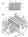
- FIGS. 1 (in section) and 2 (partially cutaway view) recall, for the proper understanding of the invention, the general structure of ovens with open chambers "advancing fire " .
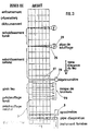
- FIG. 3 shows, in diagrammatic plan view, the structure of an oven with open chambers according to the invention.
- Figure 4 shows, in section, the practical implementation of the invention on the suction pipe, in a first embodiment.
- Figure 5 shows the smoke opacity measurement device.
- Figures 6 and 7 show two alternative embodiments of the smoke opacimetry.
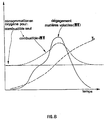
- FIG. 8 diagrams the evolution, as a function of time, of the temperature TA of the anodes during cooking of the release of volatile materials emitted by these anodes and of the oxygen consumption for burning the fuel injected by the burners plus the volatile materials .
- baffles 7 of the heating partitions The purpose of the baffles 7 of the heating partitions is to lengthen the path of the hot gases and thereby homogenize the temperature of the products in the cells 5.
- the closable openings 8 allow the installation of the burner rails (not shown), blow pipes and air suction, and in some cases, measuring devices (thermocouples, depressometers).
- the successive chambers are separated by transverse walls 9.
- the major axis of the furnace is indicated by the line XX '.
- each nozzle 2 between the suction pipe 3 and the corresponding opening 8 a movable flap 11 controlled by a motor 12 (the term "motor being taken here in its broadest sense, including example, control by hydraulic or mechanical motorized cylinder).
- This suction pipe 3 is placed on the first chamber in natural preheating (fig. 2 and 3).
- the nozzles of the blowing pipe 25 are also equipped with motorized movable flaps, for a purpose which will be specified a little later.
- the smoke opacity measurement could, in theory, be carried out directly in the nozzle 2.
- Another way of not being obstructed by the turbulence of the smoke is to use, as a measurement chamber, an auxiliary chamber 18, FIG. 6, in which part of the smoke flow is derived, provided that the inlet is connected to an outlet 8A corresponding to an upward flow zone, and the outlet to an outlet 8B corresponding to a downward flow.
- FIG. 7 shows another embodiment in which the nozzle 2 has a straight length sufficient for it to be admitted that the turbulence therein is relatively limited and does not disturb the opacity measurement.
- the measurement probes are placed on a rigid plate forming the upper part of the measurement chamber.
- the emitting probe 19 is connected, by optical fiber 22A, to a light source emitting in modulated visible light, placed in the box 21.
- the axis of the emitting probe 19, which illuminates the smoke in the chamber, forms an angle of about 45 ° with the plane of the wall of the chamber 18. It is the same for the receiving probe 20 which is arranged about ten centimeters from the transmitting probe.
- the axes of the two probes form an angle of about 80 ° between them. In this way, the light emitted by the probe 19 cannot in any way directly reach the probe 20 which only captures the light reflected by the solid particles suspended in the smoke (unburnt and dust), and which are symbolized by the small black dots in Figure 5 (this value of 80 ° is given for information).
- This reflected light is led, by the optical fiber 22B, to the box 21, where it is detected by photodiodes.
- the modulated electrical signal is cleared of a possible component continuous parasite then linearly converted into an analog (or digital) output signal which, after processing and upgrading required, controls the motor 12 controlling the position of the movable flap 11 placed in the nozzle 2. Furthermore, this same signal can be translated, after prior calibration, into milligrams of solid particles per m 3 of smoke.
- the regulation, according to this principle, of the whole chamber furnace, implies that this device is installed on each of the outputs of the heating partitions, which can be, for example, 7 in number (case of FIGS. 2 and 3).
- the measurement box 21 can be common to all of the opacimeters, each channel being able to be provided with a separate detector-amplifier, or else with a single multiplexed detector-amplifier.
- the box 21 Given the high temperature prevailing in the vicinity of the oven, the box 21 must be placed at a certain distance, which can be of the order of one or more tens of meters.
- the fiber optic link allows a temperature of up to 350 ° C and, if necessary, 400 ° C with some precautions.
- the emitting and receiving probes comprise an auxiliary circuit 23 for scanning fresh air, which has the aim of preventing deposits of solid materials on the end 24 of the optical fiber.
- the function of the regulation is to optimize the cooking of the anodes, that is to say to impose on the carbonaceous blocks and the gases a temperature rise curve allowing each phase of the cooking to take place under optimal conditions and this, by reducing fuel consumption to the strict minimum, therefore by optimizing the combustion regime.
- the cooking temperature follows a setpoint curve, a regulation specific to each burner bank, controls the frequency and amplitude of the fuel injections into the different burners (which operate intermittently. These injections are carried out by pulses of predetermined duration and frequency assigned by the regulation automaton
- the temperature taken into account for this regulation is the gas temperature measured after the burners.
- the regulation which takes into account both the variation of the temperature of the gases in the zone in natural preheating and the measures of opacity of these gases and of the vacuum, according to a specific algorithm, acts on the gas flow in each line of partition.
- each row of heating partition 1 is independent - and isolated - from the other rows, experience shows that a variation of the depression in a partition 1 can have more or less marked repercussions on the depression in the other partitions. Therefore, it is preferable not to control the vacuum in each partition independently of the vacuum and the temperature measured in the other partitions of the room concerned, but to compare them and treat them according to a particular algorithm, to so as to avoid any sudden variation on any of the flaps.
- a time delay is introduced, when an opacity increases outside the range Y ⁇ AY, so as to return to phase B only if the opacity is still outside this range at the end of the delay period.
- the opacity measurements Y and the temperature measurements TG would cause an antagonistic action on the shutter 1
- the opacity would be temporarily discarded, in order to ensure as a priority a correct rise in the temperature TG of the gases in the area in natural preheating.
- the quantity of volatile matter is known as follows: the temperature TG of the gases in the chambers in natural preheating is measured. By mathematical modeling (and experimental verification), a correlation curve was established between the temperature TG of the combustion gases circulating in the partitions and the actual temperature TA of the anodes in the chambers in natural preheating.
- the invention was applied to an industrial chamber oven, producing anodes for a series of electrolysis tanks operating at 280 KA.
- This oven has 40 rooms divided into 2 parallel rows. Each room has 6 alternating cells with 7 heating partitions.
- the opacimetry chamber, mounted in bypass between the first and the third workman, is a horizontal cylinder 500 mm in diameter and 900 mm long.
- the diameter of the inlet 25A and outlet 25B channels is 100 mm (FIG. 6).
- the two probes are placed approximately 100 mm apart and form an angle of approximately 80 ° between them (indicative value).
- the adjustment flaps are controlled by motorized jacks which are themselves controlled from the control box.
- thermoelectric couples thermoelectric couples
- vacuum vacuum
- the limits set for variations in depression are 40 to 180 Pa with initialization at 80 Pa.
- the overpressure in the last room in natural cooling upstream of the open fire zone was maintained at around 20 Pa. After 6 months of operation, there was a decrease in the cooking energy consumption of the anodes by approximately 15 to 16%.
- the invention applies to the firing of all types of carbon blocks: anodes and cathodes for the electrolysis of aluminum, cylindrical electrodes for electrometallurgy, electrodes and other shaped parts intended to be subsequently graphitized.
Landscapes
- Engineering & Computer Science (AREA)
- Mechanical Engineering (AREA)
- General Engineering & Computer Science (AREA)
- Chemical & Material Sciences (AREA)
- Combustion & Propulsion (AREA)
- Baking, Grill, Roasting (AREA)
- Waste-Gas Treatment And Other Accessory Devices For Furnaces (AREA)
- Furnace Details (AREA)
- Regulation And Control Of Combustion (AREA)
- Furnace Housings, Linings, Walls, And Ceilings (AREA)
- Tunnel Furnaces (AREA)
- Muffle Furnaces And Rotary Kilns (AREA)
- Incineration Of Waste (AREA)
- Vertical, Hearth, Or Arc Furnaces (AREA)
Priority Applications (1)
| Application Number | Priority Date | Filing Date | Title |
|---|---|---|---|
| AT87420153T ATE46029T1 (de) | 1986-06-17 | 1987-06-12 | Verfahren und vorrichtung zur optimierung des brennens in einem offenen kammerofen zum brennen von rohstoffhaltigen bloecken. |
Applications Claiming Priority (4)
| Application Number | Priority Date | Filing Date | Title |
|---|---|---|---|
| FR8608987 | 1986-06-17 | ||
| FR8608987A FR2600152B1 (fr) | 1986-06-17 | 1986-06-17 | Dispositif et procede d'optimisation de la combustion dans les fours a chambres pour la cuisson de blocs carbones |
| FR878705466A FR2614093B2 (fr) | 1987-04-14 | 1987-04-14 | Perfectionnements au procede et au dispositif d'optimisation de la combustion dans les fours a chambres pour la cuisson de blocs carbones |
| FR8705466 | 1987-04-14 |
Publications (2)
| Publication Number | Publication Date |
|---|---|
| EP0252856A1 EP0252856A1 (fr) | 1988-01-13 |
| EP0252856B1 true EP0252856B1 (fr) | 1989-08-30 |
Family
ID=26225338
Family Applications (1)
| Application Number | Title | Priority Date | Filing Date |
|---|---|---|---|
| EP87420153A Expired EP0252856B1 (fr) | 1986-06-17 | 1987-06-12 | Dispositif et procédé d'optimisation de la combustion dans les fours à chambres pour la cuisson de blocs carbones |
Country Status (25)
| Country | Link |
|---|---|
| US (1) | US4859175A (pt) |
| EP (1) | EP0252856B1 (pt) |
| JP (1) | JPS63503560A (pt) |
| KR (1) | KR920004473B1 (pt) |
| CN (1) | CN1007752B (pt) |
| AU (1) | AU594480B2 (pt) |
| BR (1) | BR8707345A (pt) |
| CA (1) | CA1317421C (pt) |
| CZ (1) | CZ439587A3 (pt) |
| DE (1) | DE3760518D1 (pt) |
| EG (1) | EG18443A (pt) |
| ES (1) | ES2010215B3 (pt) |
| GR (1) | GR3000140T3 (pt) |
| HU (1) | HU201144B (pt) |
| IS (1) | IS1424B6 (pt) |
| MX (1) | MX169261B (pt) |
| MY (1) | MY100888A (pt) |
| NO (1) | NO170172C (pt) |
| NZ (1) | NZ220691A (pt) |
| OA (1) | OA08809A (pt) |
| PL (1) | PL158244B1 (pt) |
| SU (1) | SU1738102A3 (pt) |
| TR (1) | TR22915A (pt) |
| WO (1) | WO1987007938A1 (pt) |
| YU (2) | YU45038B (pt) |
Families Citing this family (27)
| Publication number | Priority date | Publication date | Assignee | Title |
|---|---|---|---|---|
| US5078595A (en) * | 1989-07-14 | 1992-01-07 | Roenigk Howard L | Carbon flue wall and method of making |
| WO1991019147A1 (en) * | 1990-05-29 | 1991-12-12 | Alcoa Of Australia Limited | Method and apparatus for control of carbon baking furnaces |
| DE4119320C1 (pt) * | 1991-06-12 | 1993-01-07 | Riedhammer Gmbh Und Co Kg, 8500 Nuernberg, De | |
| NO174364C (no) * | 1991-11-06 | 1994-04-20 | Norsk Hydro As | Anordning ved ringkammerovn |
| NO180215C (no) * | 1995-02-10 | 1997-03-05 | Norsk Hydro As | Anordning ved mottrykksvifte i en ringkammerovn |
| EP0899250B1 (de) * | 1997-08-25 | 2004-08-04 | Innovatherm Prof. Dr. Leisenberg GmbH & Co. KG | Verfahren zur Prozessführung eines Anodenbrennofens |
| US6436335B1 (en) | 1997-08-25 | 2002-08-20 | Innovatherm Prof. Dr. Leisenberg Gmbh & Co. Kg | Method for controlling a carbon baking furnace |
| FR2777072B1 (fr) * | 1998-04-03 | 2000-05-19 | Pechiney Aluminium | Procede et dispositif de regulation des fours de cuisson a feu tournant |
| FR2779811B1 (fr) * | 1998-06-11 | 2000-07-28 | Pechiney Aluminium | Four a feu tournant a flux central tubulaire |
| FR2825455B1 (fr) * | 2001-05-30 | 2003-07-11 | Pechiney Aluminium | Procede et dispositif de refroidissement des alveoles d'un four a chambres |
| CH695870A5 (de) * | 2002-09-23 | 2006-09-29 | R & D Carbon Ltd | Optimierung der Pechdampfverbrennung in einem Brennofen für Kohlenstoffelektroden. |
| EP1742003A1 (de) * | 2005-07-04 | 2007-01-10 | Innovatherm Prof. Dr. Leisenberg GmbH & Co. KG | Verfahren zur Prozessführung eines offenen Anodenbrennofens |
| FR2917818B1 (fr) * | 2007-06-21 | 2009-09-25 | Solios Environnement Sa | Procede d'optimisation de la commande d'un centre de traitement des fumees d'un four a feu tournant de cuisson de blocs carbones |
| FR2918164B1 (fr) * | 2007-06-29 | 2009-09-25 | Solios Environnement Sa | Procede de surveillance d'un conduit des fumees reliant un four de cuisson de blocs carbones a un centre de traitement des fumees |
| FR2927410B1 (fr) * | 2008-02-13 | 2010-04-09 | Solios Carbone | Obturateur a joint d'etancheite peripherique gonflable et systeme d'obturation le comportant pour lucarne de four a chambres |
| FR2928206B1 (fr) * | 2008-02-29 | 2011-04-22 | Solios Carbone | Procede de detection de cloison au moins partiellement bouchee pour four a chambres |
| FR2940417B1 (fr) * | 2008-12-24 | 2012-11-30 | Alcan Int Ltd | Procede et systeme de controle du fonctionnement d'une installation de cuisson de blocs carbones. |
| FR2946737B1 (fr) * | 2009-06-15 | 2013-11-15 | Alcan Int Ltd | Procede de regulation d'un four de cuisson de blocs carbones et four adapte a sa mise en oeuvre. |
| DE102009046937B4 (de) * | 2009-11-20 | 2019-12-05 | Innovatherm Prof. Dr. Leisenberg Gmbh + Co. Kg | Verfahren und Vorrichtung zur Herstellung von Anoden |
| RU2452910C2 (ru) * | 2010-08-04 | 2012-06-10 | Федеральное государственное унитарное предприятие "Государственный научно-исследовательский институт конструкционных материалов на основе графита "НИИграфит" | Электрическая печь графитации |
| CA2847822A1 (fr) * | 2011-09-08 | 2013-03-14 | Solios Carbone | Dispositif et procede d'optimisation de la combustion dans des lignes de cloisons d'un four a chambres pour la cuisson de blocs carbones. |
| US20130108974A1 (en) * | 2011-10-26 | 2013-05-02 | Fluor Technologies Corporation | Carbon baking heat recovery firing system |
| FR3012590B1 (fr) * | 2013-10-31 | 2018-01-05 | Solios Carbone | Procede de regulation d'un four a chambres a feu(x) tournant(s) pour la cuisson de blocs carbones |
| CN105463508B (zh) * | 2015-11-23 | 2017-12-12 | 中国铝业股份有限公司 | 一种燃气加热的阴极炭块组预热装置 |
| BR102017020063A2 (pt) * | 2017-09-19 | 2019-04-16 | Clean Sistemas De Automação Industrial Ltda. | Forno móvel modular, sistema de queima e método de operação de sistema de queima |
| US11703280B2 (en) | 2019-03-08 | 2023-07-18 | Maerz Ofenbau Ag | Method and shaft furnace for burning carbon-containing material in a shaft furnace |
| CN117006859B (zh) * | 2023-08-07 | 2024-02-23 | 怀来西玛通设备科技有限公司 | 一种炭素均质均等焙烧智能控制方法、系统及存储介质 |
Family Cites Families (10)
| Publication number | Priority date | Publication date | Assignee | Title |
|---|---|---|---|---|
| FR540621A (fr) * | 1915-03-16 | 1922-07-13 | Gehnrich Indirect Heat Oven Co | Four sectionnel transportable |
| US4017186A (en) * | 1975-03-05 | 1977-04-12 | Environmental Systems Corporation | Electro-optical method and system for in situ measurements of particulate mass density |
| US4043743A (en) * | 1976-08-09 | 1977-08-23 | B.S.C. Industries Corporation | Combustion control system |
| IT1114515B (it) * | 1979-02-05 | 1986-01-27 | Elettrocarbonium Spa | Perfezionamento nella regolazione dei forni continui ad anello di tipo hoffmann |
| US4269592A (en) * | 1980-02-08 | 1981-05-26 | Benton Charles M | Control of combustibility of volatile hydrocarbons and particulate matter in an exhaust gas stream by use of a high velocity burner in a carbon bake ring furnace |
| CH651380A5 (de) * | 1980-08-15 | 1985-09-13 | Alusuisse | Offener ringkammerofen fuer die herstellung von kohlenstoffhaltigen formkoerpern und verfahren zu dessen betrieb. |
| US4382778A (en) * | 1981-09-04 | 1983-05-10 | Noranda Mines Limited | Method and apparatus for reducing excess air inleakage into an open ring-type carbon baking furnace |
| FR2515799B1 (fr) * | 1981-10-29 | 1986-04-04 | Pechiney Aluminium | Dispositif de chauffage pour fours de cuisson ouverts a feu tournant et procede de mise en oeuvre de ce dispositif |
| FR2535834B1 (fr) * | 1982-11-09 | 1987-11-06 | Pechiney Aluminium | Four a chambres ouvertes pour la cuisson de blocs carbones, comportant une pipe de soufflage |
| EP0133842A1 (de) * | 1983-08-11 | 1985-03-06 | Schweizerische Aluminium Ag | Verfahren zum Betreiben eines offenen Ringkammerofens zum Herstellen von kohlenstoffhaltigen Formkörpern sowie eine Vorrichtung zur Durchführung des Verfahrens |
-
1987
- 1987-06-12 ES ES87420153T patent/ES2010215B3/es not_active Expired
- 1987-06-12 HU HU873476A patent/HU201144B/hu not_active IP Right Cessation
- 1987-06-12 US US07/156,913 patent/US4859175A/en not_active Expired - Fee Related
- 1987-06-12 AU AU75141/87A patent/AU594480B2/en not_active Ceased
- 1987-06-12 WO PCT/FR1987/000213 patent/WO1987007938A1/fr unknown
- 1987-06-12 EP EP87420153A patent/EP0252856B1/fr not_active Expired
- 1987-06-12 BR BR8707345A patent/BR8707345A/pt not_active IP Right Cessation
- 1987-06-12 JP JP62503678A patent/JPS63503560A/ja active Granted
- 1987-06-12 KR KR1019870701264A patent/KR920004473B1/ko not_active IP Right Cessation
- 1987-06-12 DE DE8787420153T patent/DE3760518D1/de not_active Expired
- 1987-06-15 CN CN87104218A patent/CN1007752B/zh not_active Expired
- 1987-06-15 EG EG348/87A patent/EG18443A/xx active
- 1987-06-15 YU YU1113/87A patent/YU45038B/xx unknown
- 1987-06-15 NZ NZ220691A patent/NZ220691A/xx unknown
- 1987-06-15 MX MX006930A patent/MX169261B/es unknown
- 1987-06-15 CZ CS874395A patent/CZ439587A3/cs unknown
- 1987-06-15 MY MYPI87000810A patent/MY100888A/en unknown
- 1987-06-16 CA CA000539807A patent/CA1317421C/fr not_active Expired - Fee Related
- 1987-06-16 IS IS3231A patent/IS1424B6/is unknown
- 1987-06-17 TR TR424/87A patent/TR22915A/xx unknown
- 1987-06-17 PL PL1987266318A patent/PL158244B1/pl unknown
-
1988
- 1988-02-16 NO NO880676A patent/NO170172C/no unknown
- 1988-02-17 OA OA59286A patent/OA08809A/xx unknown
- 1988-02-17 SU SU884355213A patent/SU1738102A3/ru active
- 1988-05-27 YU YU103788A patent/YU46259B/sh unknown
-
1989
- 1989-08-31 GR GR89400054T patent/GR3000140T3/el unknown
Also Published As
Similar Documents
| Publication | Publication Date | Title |
|---|---|---|
| EP0252856B1 (fr) | Dispositif et procédé d'optimisation de la combustion dans les fours à chambres pour la cuisson de blocs carbones | |
| CA2764748C (fr) | Procede de regulation d'un four de cuisson d'anodes et four adapte a sa mise en oeuvre | |
| CA2324935C (fr) | Procede et dispositif de regulation des fours de cuisson a feu tournant | |
| FR2600152A1 (fr) | Dispositif et procede d'optimisation de la combustion dans les fours a chambres pour la cuisson de blocs carbones | |
| CA2747693A1 (fr) | Procede et systeme de controle du fonctionnement d'une installation de cuisson de blocs carbones | |
| CA2772693C (fr) | Methode de caracterisation de la combustion dans des lignes de cloisons d'un four a chambres a feu(x) tournant(s) | |
| EP2257753B1 (fr) | Procede de detection de cloison au moins partiellement bouchee pour four a chambres | |
| EP4055325B1 (fr) | Installation de combustion | |
| CA2924723C (fr) | Procede d'injection de combustible gazeux dans un four a chambres a feu(x) tournant(s) | |
| FR2556826A1 (fr) | Procede et dispositif pour l'exploitation d'un four tunnel a auto-combustion de produits ceramiques | |
| AU595098B2 (en) | Infra red burner system for furnaces | |
| FR3103027A1 (fr) | Procédé de régulation d’une installation de combustion, ainsi qu’installation de combustion correspondante | |
| EP3063487B1 (fr) | Procédé de régulation d'un four à chambres à feu(x) tournant(s) pour la cuisson de blocs carbones | |
| FR3104683A1 (fr) | Procédé de régulation d’une installation de combustion, ainsi qu’installation de combustion correspondante | |
| FR2963413A1 (fr) | Procede et un systeme de regulation de la cuisson de blocs carbones dans une installation | |
| FR2614093A2 (fr) | Perfectionnements au procede et au dispositif d'optimisation de la combustion dans les fours a chambres pour la cuisson de blocs carbones |
Legal Events
| Date | Code | Title | Description |
|---|---|---|---|
| PUAI | Public reference made under article 153(3) epc to a published international application that has entered the european phase |
Free format text: ORIGINAL CODE: 0009012 |
|
| AK | Designated contracting states |
Kind code of ref document: A1 Designated state(s): AT CH DE ES FR GB GR IT LI NL SE |
|
| 17P | Request for examination filed |
Effective date: 19880120 |
|
| 17Q | First examination report despatched |
Effective date: 19890130 |
|
| GRAA | (expected) grant |
Free format text: ORIGINAL CODE: 0009210 |
|
| AK | Designated contracting states |
Kind code of ref document: B1 Designated state(s): AT CH DE ES FR GB GR IT LI NL SE |
|
| REF | Corresponds to: |
Ref document number: 46029 Country of ref document: AT Date of ref document: 19890915 Kind code of ref document: T |
|
| ITF | It: translation for a ep patent filed |
Owner name: ING. A. GIAMBROCONO & C. S.R.L. |
|
| REF | Corresponds to: |
Ref document number: 3760518 Country of ref document: DE Date of ref document: 19891005 |
|
| GBT | Gb: translation of ep patent filed (gb section 77(6)(a)/1977) | ||
| REG | Reference to a national code |
Ref country code: GR Ref legal event code: FG4A Free format text: 3000140 |
|
| PLBE | No opposition filed within time limit |
Free format text: ORIGINAL CODE: 0009261 |
|
| STAA | Information on the status of an ep patent application or granted ep patent |
Free format text: STATUS: NO OPPOSITION FILED WITHIN TIME LIMIT |
|
| 26N | No opposition filed | ||
| ITTA | It: last paid annual fee | ||
| PGFP | Annual fee paid to national office [announced via postgrant information from national office to epo] |
Ref country code: CH Payment date: 19930512 Year of fee payment: 7 |
|
| PGFP | Annual fee paid to national office [announced via postgrant information from national office to epo] |
Ref country code: DE Payment date: 19930513 Year of fee payment: 7 Ref country code: AT Payment date: 19930513 Year of fee payment: 7 |
|
| PGFP | Annual fee paid to national office [announced via postgrant information from national office to epo] |
Ref country code: SE Payment date: 19930517 Year of fee payment: 7 |
|
| PGFP | Annual fee paid to national office [announced via postgrant information from national office to epo] |
Ref country code: GR Payment date: 19930528 Year of fee payment: 7 |
|
| PGFP | Annual fee paid to national office [announced via postgrant information from national office to epo] |
Ref country code: ES Payment date: 19930611 Year of fee payment: 7 |
|
| PGFP | Annual fee paid to national office [announced via postgrant information from national office to epo] |
Ref country code: NL Payment date: 19930630 Year of fee payment: 7 |
|
| PG25 | Lapsed in a contracting state [announced via postgrant information from national office to epo] |
Ref country code: AT Effective date: 19940612 |
|
| PG25 | Lapsed in a contracting state [announced via postgrant information from national office to epo] |
Ref country code: SE Effective date: 19940613 Ref country code: ES Free format text: LAPSE BECAUSE OF EXPIRATION OF PROTECTION Effective date: 19940613 |
|
| PG25 | Lapsed in a contracting state [announced via postgrant information from national office to epo] |
Ref country code: LI Effective date: 19940630 Ref country code: CH Effective date: 19940630 |
|
| PG25 | Lapsed in a contracting state [announced via postgrant information from national office to epo] |
Ref country code: GR Free format text: THE PATENT HAS BEEN ANNULLED BY A DECISION OF A NATIONAL AUTHORITY Effective date: 19941231 |
|
| PG25 | Lapsed in a contracting state [announced via postgrant information from national office to epo] |
Ref country code: NL Effective date: 19950101 |
|
| EUG | Se: european patent has lapsed |
Ref document number: 87420153.6 Effective date: 19950110 |
|
| NLV4 | Nl: lapsed or anulled due to non-payment of the annual fee | ||
| REG | Reference to a national code |
Ref country code: CH Ref legal event code: PL |
|
| PG25 | Lapsed in a contracting state [announced via postgrant information from national office to epo] |
Ref country code: DE Effective date: 19950301 |
|
| EUG | Se: european patent has lapsed |
Ref document number: 87420153.6 |
|
| REG | Reference to a national code |
Ref country code: GR Ref legal event code: MM2A Free format text: 3000140 |
|
| REG | Reference to a national code |
Ref country code: ES Ref legal event code: FD2A Effective date: 19990601 |
|
| REG | Reference to a national code |
Ref country code: GB Ref legal event code: IF02 |
|
| PG25 | Lapsed in a contracting state [announced via postgrant information from national office to epo] |
Ref country code: IT Free format text: LAPSE BECAUSE OF NON-PAYMENT OF DUE FEES;WARNING: LAPSES OF ITALIAN PATENTS WITH EFFECTIVE DATE BEFORE 2007 MAY HAVE OCCURRED AT ANY TIME BEFORE 2007. THE CORRECT EFFECTIVE DATE MAY BE DIFFERENT FROM THE ONE RECORDED. Effective date: 20050612 |
|
| PGFP | Annual fee paid to national office [announced via postgrant information from national office to epo] |
Ref country code: GB Payment date: 20060519 Year of fee payment: 20 |
|
| PGFP | Annual fee paid to national office [announced via postgrant information from national office to epo] |
Ref country code: FR Payment date: 20060620 Year of fee payment: 20 |
|
| REG | Reference to a national code |
Ref country code: GB Ref legal event code: PE20 |
|
| PG25 | Lapsed in a contracting state [announced via postgrant information from national office to epo] |
Ref country code: GB Free format text: LAPSE BECAUSE OF EXPIRATION OF PROTECTION Effective date: 20070611 |