EP0252800A1 - Switch especially for the control of wind screen washers and wipers of motor vehicles - Google Patents
Switch especially for the control of wind screen washers and wipers of motor vehicles Download PDFInfo
- Publication number
- EP0252800A1 EP0252800A1 EP87401449A EP87401449A EP0252800A1 EP 0252800 A1 EP0252800 A1 EP 0252800A1 EP 87401449 A EP87401449 A EP 87401449A EP 87401449 A EP87401449 A EP 87401449A EP 0252800 A1 EP0252800 A1 EP 0252800A1
- Authority
- EP
- European Patent Office
- Prior art keywords
- axis
- main contact
- contact holder
- housing
- contact carrier
- Prior art date
- Legal status (The legal status is an assumption and is not a legal conclusion. Google has not performed a legal analysis and makes no representation as to the accuracy of the status listed.)
- Granted
Links
- 238000005406 washing Methods 0.000 claims description 6
- 241000446313 Lamella Species 0.000 description 2
- 238000013459 approach Methods 0.000 description 2
- 230000000295 complement effect Effects 0.000 description 2
- 230000006835 compression Effects 0.000 description 1
- 238000007906 compression Methods 0.000 description 1
- 238000010141 design making Methods 0.000 description 1
- 230000008030 elimination Effects 0.000 description 1
- 238000003379 elimination reaction Methods 0.000 description 1
- 230000000284 resting effect Effects 0.000 description 1
Images


Classifications
-
- H—ELECTRICITY
- H01—ELECTRIC ELEMENTS
- H01H—ELECTRIC SWITCHES; RELAYS; SELECTORS; EMERGENCY PROTECTIVE DEVICES
- H01H25/00—Switches with compound movement of handle or other operating part
- H01H25/04—Operating part movable angularly in more than one plane, e.g. joystick
-
- B—PERFORMING OPERATIONS; TRANSPORTING
- B60—VEHICLES IN GENERAL
- B60Q—ARRANGEMENT OF SIGNALLING OR LIGHTING DEVICES, THE MOUNTING OR SUPPORTING THEREOF OR CIRCUITS THEREFOR, FOR VEHICLES IN GENERAL
- B60Q1/00—Arrangement of optical signalling or lighting devices, the mounting or supporting thereof or circuits therefor
- B60Q1/02—Arrangement of optical signalling or lighting devices, the mounting or supporting thereof or circuits therefor the devices being primarily intended to illuminate the way ahead or to illuminate other areas of way or environments
- B60Q1/04—Arrangement of optical signalling or lighting devices, the mounting or supporting thereof or circuits therefor the devices being primarily intended to illuminate the way ahead or to illuminate other areas of way or environments the devices being headlights
- B60Q1/14—Arrangement of optical signalling or lighting devices, the mounting or supporting thereof or circuits therefor the devices being primarily intended to illuminate the way ahead or to illuminate other areas of way or environments the devices being headlights having dimming means
- B60Q1/1446—Arrangement of optical signalling or lighting devices, the mounting or supporting thereof or circuits therefor the devices being primarily intended to illuminate the way ahead or to illuminate other areas of way or environments the devices being headlights having dimming means controlled by mechanically actuated switches
- B60Q1/1453—Hand actuated switches
- B60Q1/1461—Multifunction switches for dimming headlights and controlling additional devices, e.g. for controlling direction indicating lights
- B60Q1/1469—Multifunction switches for dimming headlights and controlling additional devices, e.g. for controlling direction indicating lights controlled by or attached to a single lever, e.g. steering column stalk switches
Definitions
- the wall 332 supports on the outside of the housing 338 a cylindrical journal 340.
- the cylindrical journal 340 is coaxial with the axis 302 and extends perpendicular to the wall 332.
- the recess 450 is defined by two main webs 452, 454 which extend substantially parallel to the wall 332 of the main contact carrier 300.
Landscapes
- Engineering & Computer Science (AREA)
- Mechanical Engineering (AREA)
- Switches With Compound Operations (AREA)
Abstract
Description
La présente invention concerne le domaine des commutateurs, et tout particulièrement des commutateurs pour la commande de lave-essuie-glace de véhicule automobile.The present invention relates to the field of switches, and more particularly switches for controlling windshield wiper washers of a motor vehicle.
La présente invention concerne plus précisément un commutateur du type comprenant une porte-contact principal monté à pivotement dans un boîtier autour d'un premier axe, un porte-contact auxiliaire monté à pivotement sur le boîtier autour d'un second axe sensiblement orthogonal au premier axe, une manette engagée sur le porte-contact principal pour être liée à celui-ci lors d'une rotation autour du premier axe tout en pouvant pivoter librement par rapport au porte-contact principal lors d'un pivotement de la manette autour d'un axe parallèle au second axe, et des moyens de liaison assurant une liaison fonctionnelle entre la manette et le porte-contact auxiliaire, telle que le pivotement de la manette et du porte-contact principal autour du premier axe n'agissent pas sur le porte-contact auxiliaire, mais que le pivotement de la manette autour de l'axe parallèle au second axe déplace le porte-contact auxiliaire à pivotement autour du second axe.The present invention relates more precisely to a switch of the type comprising a main contact carrier pivotally mounted in a housing around a first axis, an auxiliary contact carrier pivotally mounted on the housing around a second axis substantially orthogonal to the first axis, a lever engaged on the main contact holder to be linked to the latter during a rotation around the first axis while being able to pivot freely relative to the main contact holder during a pivoting of the lever around an axis parallel to the second axis, and connecting means ensuring a functional connection between the lever and the auxiliary contact holder, such that the pivoting of the lever and of the main contact holder around the first axis does not act on the door - auxiliary contact, but that the pivoting of the lever around the axis parallel to the second axis moves the auxiliary contact carrier to pivot about the second axis.
Un commutateur de ce type est décrit par exemple dans le document DE-U-73 20 723.A switch of this type is described for example in document DE-U-73 20 723.
La présente invention a pour but de proposer un commutateur de conception simple, robuste et économique permettant de commander à l'aide d'une manette unique une multiplicité de fonctions.The object of the present invention is to propose a switch of simple, robust and economical design making it possible to control, using a single lever, a multiplicity of functions.
Un but principal de la présente invention est de proposer un commutateur pour la commande de lave-essuie-glace de véhicule automobile apte à commander à l'aide d'une manette unique les organes essuie-lave glace avant et les organes essuie-lave vitre arrière, en autorisant une commande séparée des organes essuie-glace avant et essuie-vitre arrière et des organes lave-glace avant et lave-vitre arrière, et en permettant par ailleurs de choisir les vitesses de déplacement des organes essuie-glace avant parmi une pluralité de vitesses ou de modes d'entraînement disponibles.A main object of the present invention is to provide a switch for controlling the windshield wiper washer of a motor vehicle capable of controlling, with the aid of a single lever, the front windscreen wiper washer members and the window washer wiper members. rear, by authorizing a separate control of the front wiper and rear screen wiper members and of the front windscreen washer and rear screen washer members, and also allowing the speed of movement of the front wiper members to be chosen from among multiple speeds or drive modes available.
Un autre but de la présente invention est de proposer un commutateur présentant un jeu de fonctionnement très faible.Another object of the present invention is to provide a switch having a very small operating clearance.
Un autre but de la présente invention est de proposer un commutateur présentant un bruit de fonctionnement négligeable.Another object of the present invention is to provide a switch having negligible operating noise.
Ces différents buts sont atteints, selon la présente invention, grâce à un commutateur du type précité dans lequel les moyens de liaison prévus entre la manette et le porte-contact auxiliaire sont formés d'un doigt de commande solidaire de la manette et formé d'un secteur d'anneau centré sur le premier axe.These various aims are achieved, according to the present invention, by means of a switch of the aforementioned type in which the connecting means provided between the lever and the auxiliary contact carrier are formed by a control finger integral with the lever and formed by a ring sector centered on the first axis.
De préférence, le doigt de commande précité est engagé dans une lumière traversant le porte-contact auxiliaire.Preferably, the aforementioned control finger is engaged in a light passing through the auxiliary contact carrier.
De préférence, selon l'invention, le commutateur comprend des moyens d'indexation du porte-contact principal comportant un pion supportant un galet sollicité par ressort contre un ensemble de cames définies sur le boîtier.Preferably, according to the invention, the switch comprises means for indexing the main contact carrier comprising a pin supporting a roller spring-loaded against a set of cams defined on the housing.
De façon avantageuse, le commutateur comprend de plus des moyens d'indexation du porte-contact auxiliaire comportant un organe d'indexation sollicité par ressort contre un ensemble de cames auxiliaires définies sur le porte-contact principal.Advantageously, the switch further comprises means for indexing the auxiliary contact holder comprising an indexing member biased by spring against a set of auxiliary cams defined on the main contact holder.
De façon avantageuse, selon l'invention, chaque porte-contact supporte deux plots de contact qui se déplacent contre des lamelles associées portées par le boîtier.Advantageously, according to the invention, each contact carrier supports two contact pads which move against associated strips carried by the housing.
D'autres caractéristiques, buts et avantages de la présente invention apparaîtront à la lecture de la description détaillée qui va suivre et en regard des dessins annexés, donnés à titre d'exemples non limitatifs et sur lesquels :
- . la figure 1 représente une vue schématique en perspective éclatée d'un commutateur conforme à la présente invention,
- . la figure 2 représente une vue schématique en coupe du porte-contact principal intégré à ce commutateur selon un plan de coupe référencé II-II sur la figure 1,
- . la figure 3 représente une vue latérale schématique du porte-contact auxiliaire intégré à ce même commutateur,
- . la figure 4 représente une vue de dessus de ce porte-contact auxiliaire selon une vue illustrée par la flèche référencée IV sur la figure 3,
- . la figure 5 représente une vue en coupe du porte-contact auxiliaire selon des plans de coupe non coplanaires référencés V-V sur la figure 4,
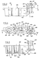
- . la figure 6 représente schématiquement les lamelles de contact intégrées au commutateur conforme à la présente invention.
- . FIG. 1 represents a schematic exploded perspective view of a switch according to the present invention,
- . FIG. 2 represents a schematic sectional view of the main contact carrier integrated into this switch according to a section plane referenced II-II in FIG. 1,
- . FIG. 3 represents a schematic side view of the auxiliary contact carrier integrated into this same switch,
- . FIG. 4 represents a top view of this auxiliary contact carrier according to a view illustrated by the arrow referenced IV in FIG. 3,
- . FIG. 5 represents a sectional view of the auxiliary contact carrier according to non-coplanar cutting planes referenced VV in FIG. 4,
- . FIG. 6 schematically represents the contact strips integrated in the switch according to the present invention.
Pour l'essentiel, le commutateur, représenté sur les figures annexées, comprend un boîtier 100, une manette 200, un porte-contact principal 300, un porte-contact auxiliaire 400 et des lamelles de contacts électriques 500.Essentially, the switch, shown in the appended figures, comprises a
Le boîtier 100 est formé par assemblage de deux demi-boîtiers 110, 120.The
Le porte-contact principal 300 est monté à pivotement surle demi-boîtier 120 autour d'un axe 302.The
Le porte-contact principal 300 comprend plus précisément un bloc 310 solidaire d'un carter 330.The
Le bloc 310 reçoit un pion d'indexage 350 et deux plots de contact 360, 362.
Le carter 330 est formé en combinaison d'une paroi plane 332 qui support deux voiles généralement parallèles entre eux 334, 336.The
Ces voiles 334, 336 sont placés d'un même côté de la paroi 332.These
La paroi 332 définit en combinaison avec les voiles 334, 336 un logement 338 généralement parallélépi pèdique complémentaire de l'extrémité 202 de la manette placée dans le boîtier 100.The
La paroi 332 supporte sur l'extérieur du logement 338 un tourillon cylindrique 340. Le tourillon cylindrique 340 est coaxial de l'axe 302 et s'étend perpendiculairement à la paroi 332.The
Le tourillon 340 est supporté à pivotement autour de l'axe 302 dans un alésage 122 ménagé dans le demi-boîtier 120. On notera que l'axe de pivotement 302 du porte-contact principal s'étend sensiblement parallèlement aux voiles 334, 336.The
Le bloc 310 du porte-contact principal 300 présente un alésage 312 qui s'étend parallèlement au plan moyen de la paroi 332 et des voiles 334, 336, c'est-à-dire perpendiculairement à l'axe d'articulation 302. L'alésage 312 présente une section droite complémentaire de celle du pion 350 précité, pour recevoir celui-ci. Sur son extrémité émergeant de l'alésage 312, le pion 350 porte à pivotement un galet 352. Le galet 352 est porté à pivotement sur le pion 350 autour d'un axe 354 parallèle à l'axe 302 précité.The
Un ressort 356 intercalé,entre le fond 313 de l'alésage 312 et le pion 350, sollicite le pion 350 et le galet 352 vers l'extérieur de l'alésage 312, contre une paroi 124 du demi-boîtier 120 présentant une pluralité de crantages comme illustré sur la figure 1.A
Le bloc 310 possède par ailleurs deux alésages 314, 316 parallèles entre eux et s'étendant sensiblement parallèlement à l'axe 302 de pivotement du porte-contact principal. Les alésages 314 et 316 débouchent sur le porte-contact principal 300 du même côté que le logement 338 défini par la paroi 332 et les voiles 334,336.The
Les alésages 314 et 316 reçoivent respectivement les plots de contact 360 et 362 précités.The
Des ressorts 361, 363 intercalés entre le fond 315, 317, respectivement, des alésages 314 et 316 et les plots de contact 360, 362 sollicitent ces derniers vers l'extérieur des alésages 314, 316 contre une série de lamelles 510 portées par le demi-boîtier 110 et dont la structure sera décrite plus en détail par la suite.Springs 361, 363 interposed between the
Comme indiqué précédemment, l'extrémité 202 de la manette 200 interne au boîtier 100 est engagée dans le logement 338 du porte-contact principal 300.As indicated above, the
Compte tenu de l'engagement ainsi défini entre la manette 200 et le porte-contact principal 300, toute sollicitation à pivotement de la manette 200 autour de l'axe 302 précité induit un pivotement du porte-contact principal 300 autour du même axe 302. Par contre, lorsqu'un utilisateur exerce sur la manette 200 une sollicitation à pivotement autour d'un axe perpendiculaire au plan moyen des voiles 334, 336 (soit perpendiculairement à l'axe 302 précité) l'extrémité 202 de la manette 200 peut pivoter autour d'un axe 204 dans le logement 338 et n'agit pas sur le porte-contact principal 300.Given the engagement thus defined between the
En d'autres termes, l'engagement de l'extrémité 202 de la manette 200 dans le logement 338 du porte-contact principal définit une liaison fonctionnelle entre la manette 200 et le porte-contact principal 300 lors d'une rotation autour de l'axe 302 tout en autorisant un pivotement libre de la manette 200 par rapport au porte-contact principal 300 lors d'un pivotement de la manette autour de l'axe 204 perpendiculaire au plan moyen des voiles 334 et 336.In other words, the engagement of the
Le guidage à pivotement de la manette 200 sur le porte-contact principal 300 autour de l'axe 204 est défini par des tourillons 206, 208 portés sur des faces opposées de l'extrémité 202 de la manette, engagés respectivement dans des ouvertures 335, 337 de portée cylindrique réalisées respectivement dans les voiles 334 et 336 précités.The pivoting guide of the
Un indexage de la manette 200 lors de son pivotement autour de l'axe 204 est défini par un pion 210. Celui-ci est logé dans un alésage 212 réalisé dans l'extrémité 202 de la manette. L'alésage 212 débouche sur la face d'extrémité 214 de la manette transversale à son axe longitudinal.An indexing of the
Le pion d'indexage 210 est sollicité, par un ressort non représenté sur les figures pour simplifier l'illustration, vers l'extérieur de l'alésage 212 contre une surface 331 du porte-contact principal 300. Cette face 331 correspond à la face du bloc 310 dirigée vers l'intérieur du logement 338. Elle s'étend perpendiculairement au plan moyen de la paroi 332 et des voiles 334 et 336.The
La face 331 précitée présente une pluralité de crantages 342, 344 recevant le pion d'indexage 210.The
Le porte-contact auxiliaire 400 est porté à pivotement sur le demi-boîtier 120 autour d'un axe 402 s'étendant parallèlement à l'axe 204 précité.The
Le guidage du porte-contact auxiliaire 400 à pivotement autour de l'axe 402 sur le demi-boîtier 120 est défini par une pluralité de lamelles 404, 406 et 408 solidaires du porte-contact auxiliaire 400, s'étendant sensiblement parallèlement entre elles et définissant une enveloppe généralement cylindrique.The guidance of the
Ces lamelles 404, 406, 408 sont équi-réparties autour de l'axe 402 précité. Selon le mode de réalisation représenté sur les figures, il est ainsi prévu trois lamelles. Ce nombre ne doit cependant pas être considéré comme limitatif.These
Les lamelles 404, 406 et 408 sont destinées à être introduites dans un alésage 126 ménagé dans le demi-boîtier 120.The
Le diamètre (référencé schématiquement D sur la figure 3) défini par l'enveloppe cylindrique des lamelles 404, 406 et 408 correspond sensiblement au diamètre de l'alésage 126 réalisé dans le demi-boîtier 120.The diameter (referenced schematically D in FIG. 3) defined by the cylindrical envelope of the
Chacune des lamelles 404, 406 et 408 porte au voisinage de son extrémité libre, et sur sa surface extérieure, une denture de section droite triangulaire 405, 407, 409.Each of the
Ces dentures définissent une enveloppe de section droite supérieure à celle de l'alésage 126 afin de maintenir le porte-contact auxiliaire 400 sur le demi-boîtier 120 après engagement élastique des lamelles 404, 406 et 408 dans l'alésage 126.These teeth define an envelope of cross section greater than that of the
Au cours de cet engagement, les lamelles élastiques 404, 406 et 408 fléchissent élastiquement en rapprochement de l'axe 402, avant de reprendre leur position de repos telle qu'illustré sur la figure 3 lorsque les dentures 405, 407 et 409 dépassent l'épaisseur de la paroi du demi-boîtier 120 présentant l'alésage 126.During this engagement, the
Pour cela la distance 1 (illustrée sur la figure 3) séparant les dentures 405, 407 et 409 de la base des lamelles 404, 406 et 408 doit être au moins légèrement supérieure à l'épaisseur de la paroi du demi- boîtier 120 présentant l'alésage 126.For this, the distance 1 (illustrated in FIG. 3) separating the
Le porte-contact auxiliaire 400 possède par ailleurs deux alésages borgnes 420, 422 recevant des plots de contact 440, 442.The
Les axes 421, 423 des alésages borgnes 420, 422 sont généralement parallèles entre eux et parallèles à l'axe 402 de pivotement du porte-contact auxiliaire 400.The
Les alésages borgnes 420, 422 débouchent sur une face commune 424 du porte-contact auxiliaire 400 transversal à l'axe de pivotement 402 et dirigée vers la paroi du demi-boîtier 120 présentant l'alésage 126.The blind bores 420, 422 open onto a
Selon le mode de réalisation réprésenté sur les figures (voir notamment figure 5) les alésages borgnes 420, 422 sont généralement tronconiques évasés vers leur ouverture, soit vers la face 424 du porte-contact auxiliaire 400.According to the embodiment shown in the figures (see in particular FIG. 5) the blind bores 420, 422 are generally frustoconical flared towards their opening, ie towards the
Des ressorts intercalés entre le fond 425, 426 des alésages 420, 422 et les plots de contact 440, 442 sollicitent ces derniers vers des lames de contact 550 supportées par la paroi du demi-boîtier 120 présentant l'alésage 126.Springs inserted between the bottom 425, 426 of the
On remarquera à l'examen de la figure 4 que de préférence les contours d'ouverture des alésages 420, 422, définis au niveau de la surface 424 du porte-contact auxiliaire 400 sont de forme ovoïde, la plus petite largeur de ce contour d'ouverture considérée parallèlement à l'axe de pivotement 302 coïncidant sensiblement avec le diamètre des plots de contacts 440, 442 tandis que la plus grande longueur de ce contour d'ouverture des alésages 420, 422 considérée perpendiculairement à l'axe 302 est largement supérieure au diamètre des plots de contact 440, 442 pour autoriser un débattement des plots de contact transversalement à l'axe 302 afin de s'adapter étroitement aux lames de contact 550 portées par le boîtier 100.It will be noted on examining FIG. 4 that preferably the opening contours of the
Comme cela apparaît à l'examen de la figure 4, le porte-contact auxiliaire 400 est de plus muni d'un évidement 450 traversant parallèlement à l'axe de pivotement 402.As appears on examining FIG. 4, the
L'évidement 450 est défni par deux voiles principaux 452, 454 qui s'étendent sensiblement parallèlement à la paroi 332 du porte-contact principal 300.The
Les voiles 452, 454 possèdent sur leur surface interne en regard 453, 455, parallèles entre elles, des protubérances hémi-cylindriques 456, 458. Ces dernières sont définies par des génératrices parallèles à l'axe de pivotement 402. Les génératrices 460, 461 des protubérances 456, 458, les plus éloignées des voiles 452, 454 qui les supportent sont définies dans un plan 459 s'étendant parallèlement aux axes d'articulation 402 et 302.The
L'évidement 450 ménagé dans le porte-contact auxiliaire 400 reçoit un doigt de commande 250 solidaire de l'extrémité 202 de la manette.The
Plus précisément encore, comme cela est illustré sur la figure 1, le doigt de commande 250 est incurvé. Ce doigt de commande 250 est formé d'un secteur annulaire centré sur l'axe de pivotement 302.More precisely still, as illustrated in FIG. 1, the
La distance séparant les génératrices 460, 461 précitées des protubérances hémi-cylindriques 456, 458 égale sensiblement la largeur du doigt de commande 250 considéré parallèlement à l'axe 302.The distance separating the
Ainsi, le doigt de commande 250 repose contre le porte-contact auxiliaire 400 au niveau des génératrices 460 et 461 précitées pour définir une liaison fonc tionnelle entre la manette 200 et le porte-contact auxiliaire 400, telle que le pivotement de la manette 200 et du porte-contact principal 300 autour du premier axe 302 n'agisse pas sur le porte-contact auxiliaire 400 (le doigt de commande 250 se déplaçant alors dans l'évidement 450 en glissant sur les génératrices 460, 461) mais que le pivotement de la manette 200 autour de l'axe 204 parallèle à l'axe 402 déplace le porte-contact auxiliaire 400 à pivotement autour de ce dernier puisque le doigt de commande 250 repose contre les génératrices 460 et 461 précitées.Thus, the
De préférence, la surface 124 du demi-boîtier 120 présente quatre crans 125, 126, 127 et 128 définissant quatre points d'indexation stable du porte-contact principal 300, lors de sa rotation autour de l'axe 302, par l'intermédiaire du galet 352.Preferably, the
Les crans 125, 126, 127 et 128 sont pour cela concaves en direction du galet d'indexation 352 et répartis sur une surface généralement cylindrique de révolution autour de l'axe 302.The
Les quatre positions stables correspondantes des plots de contact 360, 362 sont référencées 360₁, 362₁ ; 360₂, 362₂ ; 360₃, 362₃ ; et 360₄, 362₄ sur la figure 6.The four corresponding stable positions of the
On a représenté sur la figure 6A un jeu de lamelles 510 portées par le demi-boîtier 110 et aptes à coopérer avec les plots de contact 360,362 portés par le porte-contact principal 300 pour commander les organes essuie glace avant. Le jeu de lames 510 représenté sur la figure 6A est adapté pour définir successivement, selon la position du porte-contact principal 300 autour de l'axe 302 : 1) une position arrêt fixe, 2) une position marche cadencée, 3) une position première vitesse, et 4) une position deuxième vitesse.FIG. 6A shows a set of
Pour cela, le jeu de lames 510 représenté sur la figure 6A comprend une lame 511 d'alimentation positive, une lame 512 d'arrêt fixe, une lame 513 de marche cadencée, une lame 514 de première vitesse et une lame 515 de seconde vitesse.For this, the set of
En position de repos du porte-contact principal 300, pour laquelle le galet d'indexation 352 repose dans le cran 125, le plot de contact 360 repose uniquement contre la lame d'alimentation positive 511, tandis que le plot 362 relie les lames 512 et 514 pour commander un arrêt fixe des balais d'essuie glace.In the rest position of the
Dans la seconde position du porte-contact principal 300, pour laquelle le galet d'indexation 352 repose dans le cran 126, le plot de contact 360 relie la lame d'alimentation positive 511 à la lame de marche cadencée 513 pour alimenter les moyens d'entraînement cadencé, tandis que le plot de contact 360 relie toujours les lamelles 512 et 514.In the second position of the
Dans la troisième position du porte-contact principal 300, pour laquelle le galet d'indexation 352 repose dans le cran 127, le plot 360 relie la lame d'alimentation positive 511 et la lame 514 pour assurer l'entraînement des organes d'essuie glace avant selon une première vitesse, tandis que le plot de contact 362 est maintenant séparé des lames 512 et 514.In the third position of the
Enfin, dans la quatrième position du porte-contact principal 300, pour laquelle le galet d'indexation 352 repose dans le cran 128, le plot de contact 360 relie la lame d'alimentation positive 511 et la lame 515 pour assurer l'entraînement des balais d'essuie glace à une seconde vitesse, tandis que le plot 362 reste séparé des lamelles 512 et 514.Finally, in the fourth position of the
On a représenté sur la figure 6B une variante de réalisation du jeu de lamelles 510 précité. Selon cette variante de réalisation, la seconde position stable selon la figure 6A correspondant à une alimentation en marche cadencée est remplacée par une position instable de commande en première vitesse.FIG. 6B shows an alternative embodiment of the aforementioned set of
Pour cela, comme représenté sur la figure 1bis, le second cran 126 précité et prévu sur le boîtier 120 est supprimé et le premier cran 125 définit une rampe 129 inclinée progressivement en rapprochement de l'axe 302 vers le cran 127, rampe 129 qui couvre toute l'amplitude du cran 126 illustré sur la figure 1.For this, as shown in FIG. 1a, the aforementioned
Par ailleurs, la lamelle 513 de marche cadencée est supprimée et les lamelles 512ʹ et 514ʹ correspondant respectivement aux lames d'arrêt fixe 512 et de première vitesse 514 selon le mode de réalisation de la figure 6A sont adaptées en conséquence.Furthermore, the
Sur la figure 6B, on a également représenté les quatre positions des plots de contact 360 et 362 à l'aide d'indices 1,2,3 et 4 respectivement.In FIG. 6B, the four positions of the
Comme indiqué précédemment en regard de la figure 6A, dans la première position du porte-contact principal 300, pour laquelle le galet d'indexation 352 repose dans le cran 125,le plot 360 est en contact seulement contre la lame d'alimentation positive 511ʹ, tandis que le plot 362 relie la lame 512ʹ d'arrêt fixe et la lame de première vitesse 514ʹ.As indicated previously with reference to FIG. 6A, in the first position of the
Lorsque le porte-contact principal 300 est pivoté autour de l'axe 302 pour rapprocher le galet d'indexation 352 du crantage 127, le galet de contact 352 roule contre la rampe 129 définie par le cran 125 et se rapproche de l'axe 302 par compression du ressort de sollicitation 356. La seconde position assortie d'un indice 2 sur la figure 6B correspond par conséquent à une position instable, le ressort 356 ramenant le porte- contact principal vers la première position précitée lorsque la sollicitation exercée sur la manette 200 et le porte-contact principal 300 est relâchée.When the
Dans cette deuxième position le galet 360 relie la lame d'alimentation positive 511ʹ et la lame 514ʹ pour assurer l'entraînement des balais d'essuie glace selon la première vitesse, le second plot 362 reposant uniquement contre la lame de première vitesse 514ʹ.In this second position, the
Dans la troisième position du porte-contact principal 300, pour laquelle le galet d'indexation 352 repose dans le cran 127 et définit une position stable, le plot de contact 360 relie la lame d'alimentation positive 511ʹ et la lame 514ʹ, tandis que le plot 362 est séparé des lames 512ʹ et 514ʹ.In the third position of the
Enfin, dans la quatrième position du porte-contact principal 300, pour laquelle le galet d'indexation 352 repose contre le cran 128 et définit une position stable, le plot de contact 360 relie la lame d'alimentation positive 511ʹ et la lame 515ʹ pour entraîner les balais d'essuie glace à une seconde vitesse, tandis que le second plot de contact 362 reste séparé des lamelles 512ʹ et 514ʹ.Finally, in the fourth position of the
On remarquera à l'examen de la figure 1 que la lame d'alimentation positive 511 est généralement circulaire centrée sur l'axe 302. Les lames 513, 514 et 515 présentent des plages respectives de contact en regard de la lame d'alimentation positive 511 circulaires et centrées sur l'axe 302, qui se succèdent le long du trajet de déplacement du plot de contact 360, respectivement au niveau des seconde, troisième et quatrième positions de celui-ci.It will be noted on examining FIG. 1 that the
Par ailleurs, les lames 512 et 514 définissent entre elles une piste de déplacement pour le plot de contact 362. Au niveau des première et seconde positions du plot de contact 362, la distance séparant les lames 512 et 514 est inférieure au diamètre de ce plot tandis que au niveau des troisième et quatrième positions du plot de contact 362 la distance séparant les lames 512 et 514 est supérieure au diamètre du plot précité.Furthermore, the
Les dispositions des lamelles selon la variante de réalisation 510ʹ représentées sur la figure 6B reprennent celles précédemment décrites en regard de la figure 6A à ceci près que en raison de la suppression de la lame de commande en marche cadencée 513, la lame de commande en première vitesse 514ʹ étend sa plage de contact en regard de la lame d'alimentation positive 511ʹ au niveau de la seconde position (instable) du plot de contact 360.The arrangements of the lamellae according to the variant embodiment 510ʹ represented in FIG. 6B repeat those previously described with reference to FIG. 6A except that due to the elimination of the control blade in clocked
Comme indiqué précédemment la surface 331 du porte-contact principal 300 définit une indexation de la manette 200 lors de sa rotation autour de l'axe 204, et par conséquent une indexation du porte-contact auxiliaire 400 lors de sa rotation autour de l'axe 402 parallèle à l'axe 204 précité.As previously indicated, the
De préférence, comme cela est illustré sur la figure 2, la surface 331 du porte-contact principal 300 possède deux crans 342, 344 et deux rampes 346, 348 disposées respectivement de part et d'autre des crans précités.Preferably, as illustrated in FIG. 2, the
Les crans 342, 344 sont concaves vers l'axe de pivotement 204 pour recevoir le pion d'indexation 210 et définir deux positions stables de celui-ci, c'est-à-dire définir deux positions stables de la manette 200 dans sa rotation autour de l'axe 204.The
Les rampes 346, 348 convergent vers l'axe 204 en éloignement des crans 342, 344 pour définir deux positions instables de la manette 200.The
On a représenté sur la figure 6C un jeu de lamelles 550 porté par le demi-boîtier 120 et coopérant avec les plots de contact 440 et 442 portés par le porte-contact auxiliaire 400.FIG. 6C shows a set of
Sur la figure 6C on a représenté sous la référence 440₁ et 442₁ une première position occupée par les plots 440 et 442 lorsque le pion d'indexation 210 repose contre le fond du cran 342 (cette disposition correspond de préférence à une position de repos), sous la référence 440₂ et 442 ₂ la position occupée par les mêmes plots 440 et 442 lorsque la manette 200 est déplacée, en position instable sur la rampe 346, sous la référence 440₃ et 442₃ une troisième position des plots 440, 442 obtenue lorsque le pion d'indexage 210 repose contre le fond du second cran 344 et qui correspond donc également à une position stable, et enfin sous la référence 440₄, 442₄ une quatrième position des plots de contact 440, 442 , correspondant à une position instable et obtenue lorsque le pion d'indexage 214 se déplace sur la deuxième rampe 348.In FIG. 6C, the
Le cas échéant, la troisième position du porte-contact auxiliaire 440 pourrait être instable.In this case, the third position of the
Le jeu de lamelles 550 comprend cinq lamelles. La lamelle 552 correspond à une borne d'alimentation positive.The set of
La lamelle 554 sert à assurer que le balai d'essuie glace de la vitre arrière s'arrête dans une position fixe prédéterminée.The
La lame 556 sert à alimenter les moyens de lavage de la glace avant.The
La lame 558 sert à alimenter les organes d'entraînement du balai d'essuie-glace de la vitre arrière.The
Enfin, la lame 560 sert à alimenter les moyens de lavage de la vitre arrière.Finally, the
Dans la première position de la manette 200 illustrée sous la référence 440₁, 442₁ sur la figure 6C (le pion d'indexation 210 repose contre le fond du cran 342) le pion 440 relie les lames 554 et 558 pour contrôler un arrêt en position fixe prédéterminée du balai d'essuie-glace de la vitre arrière, tandis que le plot 442 repose uniquement contre la lame d'alimentation 552.In the first position of the
Dans la position instable référencée en 440₂ et 442₂ sur la figure 6C, le plot 440 relie toujours les lames 554 et 558 tandis que le plot 442 relie les lames 552 et 556 pour commander l'alimentation des moyens de lavage de la glace avant.In the unstable position referenced 440₂ and 442₂ in FIG. 6C, the
Dans la seconde position stable, pour laquelle le pion d'indexation 210 repose contre le fond du cran 344, représenté sous les références 440₃ et 442₃ sur la figure 6C, le plot de contact 440 relie la lame d'alimentation positive 552 et la lame 558 pour commander l'entraînement du balai d'essuie glace de la vitre arrière tandis que le plot 442 est en contact uniquement contre la lame 552.In the second stable position, for which the
Enfin, dans la seconde position instable pour laquelle le pion d'indexation 210 se déplace sur la seconde rampe 348 et représenté sous la référence 440₄ et 442₄ sur la figure 6C, le plot de contact 440 relie les lames 552 et 558 pour assurer l'entraînement du balai d'essuie glace de la vitre arrière, tandis que le plot de contact 442 relie la lame 560 à la lame d'alimentation positive 552 pour alimenter les moyens de lavage de la vitre arrière.Finally, in the second unstable position for which the
La lame 558 définit une piste de contacts pour le plot 440, qui est centrée sur l'axe 402 de pivotement du porte-contact auxiliaire 400. Les lames 554 et 552 définissent en regard de la lame 558 des plages de contact circulaires pour le plot 440, centrées sur le même axe 402.The
Par ailleurs, la lame d'alimentation positive 552 définit une piste de contacts pour le plot 442 centrée sur l'axe 402. De plus, les lames 556 et 560 définissent en regard de la lame 552 des pistes de contact pour le plot 442, centrées sur l'axe 402 précité.Furthermore, the
Claims (10)
. un porte-contact principal (300) monté à pivotement sur le boîtier (120) autour d'un premier axe (302),
. un porte-contact auxiliaire (400) monté à pivotement sur le boîtier (120) autour d'un second axe (402) sensiblement orthogonal au premier axe (302),
. une manette (200) engagée sur le porte-contact principal (300) pour être liée à celui-ci lors d'une rotation autour du premier axe (302) tout en pouvant pivoter librement par rapport au porte-contact principal (300) lors d'un pivotement de la manette (200) autour d'un axe (204) parallèle au second axe (402), et
. des moyens de liaison (250) assurant une liaison fonctionnelle entre la manette (200) et le porte-contact auxiliaire (400), telle que le pivotement de la manette (200) et du porte-contact principal (300) autour du premier axe (302) n'agisse pas sur le porte-contact auxiliaire (400), mais que le pivotement de la manette (200) autour de l'axe (204) parallèle au second axe (402) déplace le porte-contact auxiliaire (400), à pivotement autour du second axe (402), caractérisé par le fait que les moyens de liaison comprennent un doigt de commande (250) solidaire de la manette (200) et formé d'un secteur d'anneau centré sur le premier axe (302).1. Switch in particular for controlling windshield wiper washers of motor vehicles, of the type comprising in a housing (100):
. a main contact carrier (300) pivotally mounted on the housing (120) around a first axis (302),
. an auxiliary contact carrier (400) pivotally mounted on the housing (120) around a second axis (402) substantially orthogonal to the first axis (302),
. a handle (200) engaged on the main contact carrier (300) to be linked thereto during a rotation about the first axis (302) while being able to pivot freely relative to the main contact carrier (300) pivoting of the lever (200) about an axis (204) parallel to the second axis (402), and
. connecting means (250) ensuring a functional connection between the lever (200) and the auxiliary contact holder (400), such as the pivoting of the lever (200) and of the main contact holder (300) about the first axis (302) does not act on the auxiliary contact carrier (400), but that the pivoting of the lever (200) around the axis (204) parallel to the second axis (402) moves the auxiliary contact carrier (400 ), pivoting around the second axis (402), characterized in that the connecting means comprise a control finger (250) integral with the lever (200) and formed by a ring sector centered on the first axis (302).
Applications Claiming Priority (2)
| Application Number | Priority Date | Filing Date | Title |
|---|---|---|---|
| FR8609283 | 1986-06-26 | ||
| FR8609283A FR2600815B1 (en) | 1986-06-26 | 1986-06-26 | SWITCH IN PARTICULAR FOR THE CONTROL OF WINDSCREEN WIPER WASHER |
Publications (2)
| Publication Number | Publication Date |
|---|---|
| EP0252800A1 true EP0252800A1 (en) | 1988-01-13 |
| EP0252800B1 EP0252800B1 (en) | 1991-05-15 |
Family
ID=9336753
Family Applications (1)
| Application Number | Title | Priority Date | Filing Date |
|---|---|---|---|
| EP19870401449 Expired - Lifetime EP0252800B1 (en) | 1986-06-26 | 1987-06-24 | Switch especially for the control of wind screen washers and wipers of motor vehicles |
Country Status (4)
| Country | Link |
|---|---|
| EP (1) | EP0252800B1 (en) |
| DE (1) | DE3770067D1 (en) |
| ES (1) | ES2022398B3 (en) |
| FR (1) | FR2600815B1 (en) |
Cited By (7)
| Publication number | Priority date | Publication date | Assignee | Title |
|---|---|---|---|---|
| EP0366383A1 (en) * | 1988-10-24 | 1990-05-02 | UNITED TECHNOLOGIES AUTOMOTIVE, Inc. | Automotive beam selector switch system with "flash-to-pass" |
| EP0489654A1 (en) * | 1990-12-05 | 1992-06-10 | Jaeger | Switch assembly for a motor vehicle |
| GB2288485A (en) * | 1994-03-30 | 1995-10-18 | Niles Parts Co Ltd | Lever switch assembly |
| EP1036704A3 (en) * | 1999-03-18 | 2003-08-27 | Delphi Technologies Inc. | Steering column switch for vehicle |
| EP1655754A2 (en) * | 1997-05-20 | 2006-05-10 | Matsushita Electric Industrial Co., Ltd. | Automotive combination switch |
| DE102007006925A1 (en) * | 2007-02-05 | 2008-08-07 | Valeo Schalter Und Sensoren Gmbh | Steering column switch |
| WO2016207259A1 (en) * | 2015-06-25 | 2016-12-29 | Valeo Schalter Und Sensoren Gmbh | Steering column switch for a vehicle |
Citations (7)
| Publication number | Priority date | Publication date | Assignee | Title |
|---|---|---|---|---|
| DE1959787A1 (en) * | 1968-12-06 | 1970-06-18 | Lucas Industries Ltd | Electric switch |
| GB1257941A (en) * | 1969-07-10 | 1971-12-22 | ||
| DE7320723U (en) * | 1973-06-02 | 1973-08-23 | Kostal L | Direction of travel high beam low beam headlight flasher switch |
| US4123632A (en) * | 1975-10-27 | 1978-10-31 | Kabushiki Kaisha Tokai Rika Denki Seisakusho | Turn signal mechanism for use in motor vehicles |
| DE3115793A1 (en) * | 1981-04-18 | 1982-10-28 | Fa. Leopold Kostal, 5880 Lüdenscheid | Electrical switch |
| US4408104A (en) * | 1981-03-27 | 1983-10-04 | Kabushiki Kaisha Tokai Rika Denki Seisakusho | Lever switch arrangement for motor vehicle |
| GB2152289A (en) * | 1983-12-02 | 1985-07-31 | Kirsten Elektrotech | Electrical switch |
-
1986
- 1986-06-26 FR FR8609283A patent/FR2600815B1/en not_active Expired - Fee Related
-
1987
- 1987-06-24 EP EP19870401449 patent/EP0252800B1/en not_active Expired - Lifetime
- 1987-06-24 ES ES87401449T patent/ES2022398B3/en not_active Expired - Lifetime
- 1987-06-24 DE DE8787401449T patent/DE3770067D1/en not_active Expired - Lifetime
Patent Citations (7)
| Publication number | Priority date | Publication date | Assignee | Title |
|---|---|---|---|---|
| DE1959787A1 (en) * | 1968-12-06 | 1970-06-18 | Lucas Industries Ltd | Electric switch |
| GB1257941A (en) * | 1969-07-10 | 1971-12-22 | ||
| DE7320723U (en) * | 1973-06-02 | 1973-08-23 | Kostal L | Direction of travel high beam low beam headlight flasher switch |
| US4123632A (en) * | 1975-10-27 | 1978-10-31 | Kabushiki Kaisha Tokai Rika Denki Seisakusho | Turn signal mechanism for use in motor vehicles |
| US4408104A (en) * | 1981-03-27 | 1983-10-04 | Kabushiki Kaisha Tokai Rika Denki Seisakusho | Lever switch arrangement for motor vehicle |
| DE3115793A1 (en) * | 1981-04-18 | 1982-10-28 | Fa. Leopold Kostal, 5880 Lüdenscheid | Electrical switch |
| GB2152289A (en) * | 1983-12-02 | 1985-07-31 | Kirsten Elektrotech | Electrical switch |
Cited By (10)
| Publication number | Priority date | Publication date | Assignee | Title |
|---|---|---|---|---|
| EP0366383A1 (en) * | 1988-10-24 | 1990-05-02 | UNITED TECHNOLOGIES AUTOMOTIVE, Inc. | Automotive beam selector switch system with "flash-to-pass" |
| EP0489654A1 (en) * | 1990-12-05 | 1992-06-10 | Jaeger | Switch assembly for a motor vehicle |
| FR2670319A1 (en) * | 1990-12-05 | 1992-06-12 | Jaeger | SWITCHING ASSEMBLY FOR MOTOR VEHICLES. |
| GB2288485A (en) * | 1994-03-30 | 1995-10-18 | Niles Parts Co Ltd | Lever switch assembly |
| GB2288485B (en) * | 1994-03-30 | 1998-02-25 | Niles Parts Co Ltd | Lever switch assembly |
| EP1655754A2 (en) * | 1997-05-20 | 2006-05-10 | Matsushita Electric Industrial Co., Ltd. | Automotive combination switch |
| EP1655754A3 (en) * | 1997-05-20 | 2006-05-31 | Matsushita Electric Industrial Co., Ltd. | Automotive combination switch |
| EP1036704A3 (en) * | 1999-03-18 | 2003-08-27 | Delphi Technologies Inc. | Steering column switch for vehicle |
| DE102007006925A1 (en) * | 2007-02-05 | 2008-08-07 | Valeo Schalter Und Sensoren Gmbh | Steering column switch |
| WO2016207259A1 (en) * | 2015-06-25 | 2016-12-29 | Valeo Schalter Und Sensoren Gmbh | Steering column switch for a vehicle |
Also Published As
| Publication number | Publication date |
|---|---|
| DE3770067D1 (en) | 1991-06-20 |
| FR2600815A1 (en) | 1987-12-31 |
| FR2600815B1 (en) | 1994-03-04 |
| EP0252800B1 (en) | 1991-05-15 |
| ES2022398B3 (en) | 1991-12-01 |
Similar Documents
| Publication | Publication Date | Title |
|---|---|---|
| FR2636578A1 (en) | ORIENTATION ADJUSTMENT DEVICE FOR MOTOR VEHICLE PROJECTOR | |
| EP1437260B1 (en) | Rear-view vehicle mirror pivotable on two axes | |
| EP0252800B1 (en) | Switch especially for the control of wind screen washers and wipers of motor vehicles | |
| FR2899857A1 (en) | Windshield wiper arm disengaging device for motor vehicle, has release plate maintaining wiper arm in active sweeping position, and deformed by buckling, where wiper arm is operated between active sweeping position and disengaged position | |
| EP0755833A1 (en) | Windscreen wiper with limited lifting movement of the windscreen wiper arm | |
| EP0248716A1 (en) | Switching device for motor vehicles | |
| EP0675022B1 (en) | Electrical switch for the power supply of the direction indicators of an automotive vehicle | |
| EP1896305A1 (en) | Drive mechanism especially for a window wiping device with an elliptical wiping motion | |
| EP0255418A1 (en) | Indexing device especially for switch for motor vehicle | |
| FR2875196A1 (en) | PANTOGRAPHIC TYPE WIPES | |
| WO2007093547A1 (en) | Window wiping device with pantograph kinematics and a variable angle of attack | |
| FR2887831A1 (en) | Rotation movement conversion mechanism for e.g. pantograph type windshield wiper, has protective casing, crank mounted free in rotation around transmission shaft, and driving unit with mobile end mounted free in displacement along crank | |
| EP0566944A1 (en) | Windscreen wiper with arm of activity variable length | |
| EP0249511B2 (en) | Indicator with a needle and locating collar therefor | |
| WO2007093545A1 (en) | Rotation control mechanism especially for a window wiping device pertaining to a motor vehicle | |
| EP0098194B1 (en) | Detector switch, especially for stoppage control of motor vehicle direction indicators | |
| FR2604292A1 (en) | Improvements to electric switches, in particular for motor-vehicle windscreen wiper control | |
| EP0489654B1 (en) | Switch assembly for a motor vehicle | |
| FR2615321A1 (en) | Flick for electric switch | |
| EP0533565B1 (en) | Improved electrical commutator for automobile vehicles | |
| FR2662299A1 (en) | Electrical selector switch for motor vehicle | |
| EP1864873A1 (en) | Coupling device for flat windscreen-wiper blade | |
| FR2786546A1 (en) | Manual control for motor vehicle automatic gearbox has selector lever mounted on pivot axis with return spring for centralisation | |
| EP0703592A1 (en) | Electric switch for the supply of the parking lights of a motor vehicle | |
| FR2981030A1 (en) | Support for controlling drive system of wiper in car, has detection unit comprising conductive contact blade, where part of contact blade is received in housing that is attached with mounting plate |
Legal Events
| Date | Code | Title | Description |
|---|---|---|---|
| PUAI | Public reference made under article 153(3) epc to a published international application that has entered the european phase |
Free format text: ORIGINAL CODE: 0009012 |
|
| AK | Designated contracting states |
Kind code of ref document: A1 Designated state(s): DE ES GB IT |
|
| 17P | Request for examination filed |
Effective date: 19880208 |
|
| 17Q | First examination report despatched |
Effective date: 19900213 |
|
| GRAA | (expected) grant |
Free format text: ORIGINAL CODE: 0009210 |
|
| AK | Designated contracting states |
Kind code of ref document: B1 Designated state(s): DE ES GB IT |
|
| GBT | Gb: translation of ep patent filed (gb section 77(6)(a)/1977) | ||
| REF | Corresponds to: |
Ref document number: 3770067 Country of ref document: DE Date of ref document: 19910620 |
|
| ITF | It: translation for a ep patent filed | ||
| PLBE | No opposition filed within time limit |
Free format text: ORIGINAL CODE: 0009261 |
|
| STAA | Information on the status of an ep patent application or granted ep patent |
Free format text: STATUS: NO OPPOSITION FILED WITHIN TIME LIMIT |
|
| 26N | No opposition filed | ||
| PGFP | Annual fee paid to national office [announced via postgrant information from national office to epo] |
Ref country code: GB Payment date: 19980616 Year of fee payment: 12 |
|
| PGFP | Annual fee paid to national office [announced via postgrant information from national office to epo] |
Ref country code: ES Payment date: 19980626 Year of fee payment: 12 |
|
| PGFP | Annual fee paid to national office [announced via postgrant information from national office to epo] |
Ref country code: DE Payment date: 19980721 Year of fee payment: 12 |
|
| PG25 | Lapsed in a contracting state [announced via postgrant information from national office to epo] |
Ref country code: GB Free format text: LAPSE BECAUSE OF NON-PAYMENT OF DUE FEES Effective date: 19990624 |
|
| PG25 | Lapsed in a contracting state [announced via postgrant information from national office to epo] |
Ref country code: ES Free format text: LAPSE BECAUSE OF EXPIRATION OF PROTECTION Effective date: 19990625 |
|
| GBPC | Gb: european patent ceased through non-payment of renewal fee |
Effective date: 19990624 |
|
| PG25 | Lapsed in a contracting state [announced via postgrant information from national office to epo] |
Ref country code: DE Free format text: LAPSE BECAUSE OF NON-PAYMENT OF DUE FEES Effective date: 20000503 |
|
| REG | Reference to a national code |
Ref country code: ES Ref legal event code: FD2A Effective date: 20010601 |
|
| PG25 | Lapsed in a contracting state [announced via postgrant information from national office to epo] |
Ref country code: IT Free format text: LAPSE BECAUSE OF NON-PAYMENT OF DUE FEES;WARNING: LAPSES OF ITALIAN PATENTS WITH EFFECTIVE DATE BEFORE 2007 MAY HAVE OCCURRED AT ANY TIME BEFORE 2007. THE CORRECT EFFECTIVE DATE MAY BE DIFFERENT FROM THE ONE RECORDED. Effective date: 20050624 |