EP0252065A2 - Mobile preparation installation for road metals - Google Patents
Mobile preparation installation for road metals Download PDFInfo
- Publication number
- EP0252065A2 EP0252065A2 EP87890141A EP87890141A EP0252065A2 EP 0252065 A2 EP0252065 A2 EP 0252065A2 EP 87890141 A EP87890141 A EP 87890141A EP 87890141 A EP87890141 A EP 87890141A EP 0252065 A2 EP0252065 A2 EP 0252065A2
- Authority
- EP
- European Patent Office
- Prior art keywords
- chassis
- crusher
- conveyor
- screening device
- chassis part
- Prior art date
- Legal status (The legal status is an assumption and is not a legal conclusion. Google has not performed a legal analysis and makes no representation as to the accuracy of the status listed.)
- Granted
Links
Images
Classifications
-
- E—FIXED CONSTRUCTIONS
- E01—CONSTRUCTION OF ROADS, RAILWAYS, OR BRIDGES
- E01C—CONSTRUCTION OF, OR SURFACES FOR, ROADS, SPORTS GROUNDS, OR THE LIKE; MACHINES OR AUXILIARY TOOLS FOR CONSTRUCTION OR REPAIR
- E01C19/00—Machines, tools or auxiliary devices for preparing or distributing paving materials, for working the placed materials, or for forming, consolidating, or finishing the paving
- E01C19/02—Machines, tools or auxiliary devices for preparing or distributing paving materials, for working the placed materials, or for forming, consolidating, or finishing the paving for preparing the materials
- E01C19/05—Crushing, pulverising or disintegrating apparatus; Aggregate screening, cleaning, drying or heating apparatus; Dust-collecting arrangements specially adapted therefor
-
- B—PERFORMING OPERATIONS; TRANSPORTING
- B02—CRUSHING, PULVERISING, OR DISINTEGRATING; PREPARATORY TREATMENT OF GRAIN FOR MILLING
- B02C—CRUSHING, PULVERISING, OR DISINTEGRATING IN GENERAL; MILLING GRAIN
- B02C21/00—Disintegrating plant with or without drying of the material
- B02C21/02—Transportable disintegrating plant
Definitions
- the invention relates to a mobile ballast processing plant or the like.
- an at least biaxial chassis which receives a crusher, a screening device and a conveyor leading from the crusher outlet to the screening task.
- the invention is therefore based on the object of eliminating these deficiencies and of creating a ballast processing system of the type described at the outset, which is of particularly compact and low-cost design and is distinguished by its simple handling and good maneuverability.
- the chassis consists of two parts releasably interlocked between the front and rear axles, that crusher, screening device and conveyor are constructed on one, preferably the rear, chassis part carrying support feet in the area of the locking end, and in that conveyors and screening device on one to the other, vzw.
- the divisible chassis can be moved in the locked state like a normal trailer, but it offers the possibility of unlocking and removing a part at the installation site of the system, so that full ground clearance is then gained for the screening device projecting over the remaining chassis part and this Screening device is freely accessible.
- the sorted material can therefore be removed in any way.
- the support feet of the crusher, conveyor and screening device receiving the chassis part are pivotably arranged, so that these support feet are always in the desired position Position of the conveyor belts can be set taking position.
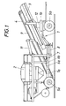
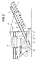
- the subject of the invention is shown schematically using an exemplary embodiment, namely show 1 and 2 the side view of a ballast processing system according to the invention in the driving state or in the operating state.
- the chassis 1 is composed of two parts 1a, 1b, of which the rear part 1a receives the rigid rear axle 5a and the front part 1b the steerable front axle 5b and is releasably locked together, for which purpose the longitudinal bars 6a, 6b of the chassis parts 1a, 1b can be pushed into one another and locked via locking pins 7.
- Crusher 2 sieving device 3 and conveyor 4 together with the associated drive and control devices are mounted on the rear chassis part 1a, pivotable support feet 8 in the area of the locking end permitting a stable installation of this rear chassis part 1a even without support from the front chassis part 1b.
- a cantilever 9 which projects beyond the locking end is provided on the rear chassis part 1a and is tensioned by means of tensioning cables 10.
- the tensioning cables 10 engage uprights 11 which are folded forward in the driving state and which place the boom 9 on a support 12 of the front chassis part 1b.
- the two chassis parts 1a, 1b are locked together, so that the system can be pulled like a trailer from place of use to place of use (Fig. 1).
- the support feet 8 are then swung out and placed in the desired position, whereupon the boom 9 is lifted from the support 12 by the uprights 11 via the tensioning cable 10 and braced for operation.
- the locking can be released by removing the plug pins 7 and the front chassis part 1b can be moved away (FIG. 2).
- the processing plant is ready for operation, the material can be entered into the crusher 2, shredded there, fed to the screening device 3 via the conveyor 4 and sorted using the screening device.
- the sieve device 3 is freely accessible on the bottom and the sorted material can be transported in any direction without being impaired by appropriate conveyor belts or the like, not shown. To change the position, it is sufficient to connect and lock the front chassis part 1b again with the rear chassis part 1a and to pull the entire chassis 1 together with the system to the desired new location.
Landscapes
- Engineering & Computer Science (AREA)
- Architecture (AREA)
- Civil Engineering (AREA)
- Structural Engineering (AREA)
- Food Science & Technology (AREA)
- Disintegrating Or Milling (AREA)
Abstract
Description
Die Erfindung bezieht sich auf eine fahrbare Schotteraufbereitungsanlage od. dgl., mit einem zumindest zweiachsigen Fahrgestell, das einen Brecher, eine Siebvorrichtung und einen vom Brecherauslaß zur Siebaufgabe führenden Förderer aufnimmt.The invention relates to a mobile ballast processing plant or the like. With an at least biaxial chassis which receives a crusher, a screening device and a conveyor leading from the crusher outlet to the screening task.
Diese fahrbaren Brecher- und Siebanlagen, die eine komplette Aufbereitungseinheit zum Zerkleinern und Sortieren von Kies, Schotter und Gestein aber auch von Erzen, Schlacken od. dgl. bilden, können für sich alleine, zusammen mit ortsfesten Einrichtung sowie in Kombination mit anderen fahrbaren Anlagen eingesetzt und je nach Verwendungszweck auch mit unterschiedlichen Brecher- und Siebkonstruktionen ausgerüstet werden. Diese fahrbaren Anlagen haben sich bisher wegen ihres geringen Personalbedarfs und ihrer Beweglichkeit, die es erlaubt, die Anlage zum aufzubereitenden Material fahren zu können und nicht das Material auf langen Transportwegen der Anlage zubrin gen zu müssen, durchaus bewährt, doch sind die bekannten Anlagen auf üblichen, der Länge nach durchgehenden Anhängerfahrgestellen aufgesetzt und die dadurch bedingte Unzugänglichkeit der Siebvorrichtungen macht die Anordnung von zusätzlichen Austragsförderbändern od. dgl. erforderlich. Die Gesamtanlage wird verhältnismäßig aufwendig und schwer und wegen des Platzbedarfes und des Gewichtes kommt es vor allem beim Straßentransport zu beträchtlichen Schwierigkeiten.These mobile crusher and screening plants, which form a complete processing unit for crushing and sorting gravel, crushed stone and stone, but also ores, slag or the like, can be used on their own, together with stationary equipment and in combination with other mobile plants and, depending on the intended use, can also be equipped with different crusher and sieve designs. These mobile systems have so far been due to their low personnel requirements and their mobility, which allows the system to be able to drive to the material to be processed and not the material on long transport routes of the system to have to be tried and tested, but the known systems are placed on conventional, lengthwise continuous trailer chassis and the resulting inaccessibility of the screening devices makes the arrangement of additional discharge conveyor belts or the like necessary. The entire system is relatively complex and heavy and due to the space and weight, especially in road transport, there are considerable difficulties.
Der Erfindung liegt daher die Aufgabe zugrunde, diese Mängel zu beseitigen und eine Schotteraufbereitungsanlage der eingangs geschilderten Art zu schaffen, die besonders kompakt und aufwandsarm aufgebaut istund sich durch ihre einfache Handhabung und gute Manövrierfähig auszeichnet.The invention is therefore based on the object of eliminating these deficiencies and of creating a ballast processing system of the type described at the outset, which is of particularly compact and low-cost design and is distinguished by its simple handling and good maneuverability.
Die Erfindung löst diese Aufgabe dadurch, daß das Fahrgestell aus zwei zwischen den Vorder- und Hinterachsen lösbar miteinander verriegelten Teilen besteht, daß Brecher, Siebvorrichtung und Förderer auf dem einen, vorzugsweise dem hinteren, im Bereich des Verriegelungsendes Stützfüße tragenden Fahrgestellteil aufgebaut sind und daß förderer und Siebvorrichtung an einem zum anderen, vzw. vorderen Fahrgestellteil hin über das Verriegelungsende hinaus vorkragenden Ausleger lagern. Das teilbare Fahrgestell läßt sich im verriegelten Zustand wie ein üblicher Anhänger verfahren, es bietet aber die Möglichkeit, am Aufstellungsort der Anlage den einen Teil zu entriegeln und zu entfernen, so daß dann für die über den verbleibenden Fahrgestellteil auskragende Siebvorrichtung volle Bodenfreiheit gewonnen wird und diese Siebvorrichtung unbehindert zugänglich ist. Das sortierte Material kann daher auf beliebige Weise abgeführt werden. Es kommt zu einer wesentlichen Vereinfachung der gesamten Anlage, es gibt keine Platzprobleme mehr, eigene, der Siebvorrichtung am Fahrgestell unmittelbar nachgeschaltete Austragsförderbänder sind unnötig und es wird ein kompakter und dennoch funktionstüchtiger Aufbau erreicht, wobei ein Fahrgestell mit recht kurzem Achsabstand möglich ist und ein wendiges, straßentaugliches Fahrzeug entsteht.The invention solves this problem in that the chassis consists of two parts releasably interlocked between the front and rear axles, that crusher, screening device and conveyor are constructed on one, preferably the rear, chassis part carrying support feet in the area of the locking end, and in that conveyors and screening device on one to the other, vzw. Store the front part of the chassis beyond the locking end and the cantilever. The divisible chassis can be moved in the locked state like a normal trailer, but it offers the possibility of unlocking and removing a part at the installation site of the system, so that full ground clearance is then gained for the screening device projecting over the remaining chassis part and this Screening device is freely accessible. The sorted material can therefore be removed in any way. There is a significant simplification of the entire system, there are no more space problems, own, the screening device Discharge conveyor belts directly connected to the chassis are unnecessary and a compact yet functional construction is achieved, whereby a chassis with a fairly short center distance is possible and an agile, roadworthy vehicle is created.
Eine zweckmäßige Konstruktion ergibt sich, wenn erfindungsgemäß am den Ausleger abstützenden Fahrgestellteil im Bereich des Verriegelungsendes Steher vorgesehen sind, über die Spannseile zum Verspannen des Auslegers verlaufen, wobei vorzugsweise die Steher um eine Querachse abklappbar am Fahrgestellteil angelenkt sind und der andere Fahrgestellteil Auflager für den Ausleger aufweist. Durch die Verspannung des Auslegers über ein Spannseil kommt es zu einer leichteren Bauweise für die Auslegerabstützung und durch das Lockern der Spannseile und ein Unterstützen des Auslegers beim Fahren durch den unterschobenen Fahrgestellteil ergibt sich ein günstiges Fahrverhalten der Anlage.An expedient construction is obtained if, according to the invention, uprights are provided on the chassis part supporting the boom in the area of the locking end, over which tensioning cables run for tensioning the boom, the uprights preferably being hinged about a transverse axis to the chassis part and the other chassis part being supports for the boom having. The bracing of the jib with a tensioning rope results in a lighter design for the jib support and by loosening the tensioning ropes and supporting the jib when driving through the undercarriage part, this results in a favorable driving behavior of the system.
Um die zum Abtransport des ausgesiebten Materials vorgesehenen Förderbänder od. dgl. in die jeweils gewünschte Richtung verlegen zu können, sind nach einer Weiterbildung der Erfindung die Stützfüße des Brecher, Förderer und Siebvorrichtung aufnehmenden Fahrgestellteiles schwenkbar angeordnet, so daß diese Stützfüße stets in einer die gewünschte Lage der Transportbänder berücksichtigenden Position gesetzt werden können.In order to be able to move the conveyor belts or the like provided for the removal of the screened-out material in the desired direction, according to a further development of the invention, the support feet of the crusher, conveyor and screening device receiving the chassis part are pivotably arranged, so that these support feet are always in the desired position Position of the conveyor belts can be set taking position.
In der Zeichnung ist der Erfindungsgegenstand schematisch an Hand eines Ausführungsbeispieles dargestellt, und zwar zeigen
Fig. 1 und 2 die Seitenansicht einer erfindungsgemäßen Schotteraufbereitungsanlage im Fahrzustand bzw. im Betriebszustand.In the drawing, the subject of the invention is shown schematically using an exemplary embodiment, namely show
1 and 2 the side view of a ballast processing system according to the invention in the driving state or in the operating state.
Auf einem zweiachsigen Fahrgestell 1 sind ein Brecher2, eine Siebvorrichtung 3 und ein vom Brecher zur Siebaufgabe führender Förderer 4 aufgebaut, so daß eine fahrbare Aufbereitungseinheit zum Zerkleinern und Sortieren von Gesteinsmaterial od. dgl. entsteht. Das Fahrgestell 1 setzt sich aus zwei Teilen 1a, 1b zusammen, von denen der hintere Teil 1a die starre Hinterachse 5a und der vordere Teil 1b die lenkbare Vorderachse 5b aufnehmen und miteinander lösbar verriegelt sind, wozu die Längsholme 6a, 6b der Fahrgestellteile 1a, 1b ineinandergeschoben und über Steckbolzen 7 verriegelt werden können.On a biaxial chassis 1, a
Brecher 2, Siebvorrichtung 3 und Förderer 4 samt den zugehörigen Antriebs- und Steuereinrichtungen sind am hinteren Fahrgestellteil 1a montiert, wobei schwenkbare Stützfüße 8 im Bereich des Verriegelungsendes ein standfestes Aufstellen dieses hinteren Fahrgestellteiles 1a auch ohne Abstützung durch den vorderen Fahrgestellteil 1b erlauben. Zur Lagerung des Förderers 4 und der Siebvorrichtung 3 ist am hinteren Fahrgestellteil 1a ein über das Verriegelungsende hinaus vorkragender Ausleger 9 vorgesehen, der über Spannseile 10 verspannt wird. Die Spannseile 10 greifen an Stehern 11 an, die im Fahrzustand vorwärtsgeklappt sind und den Ausleger 9 auf ein Auflager 12 des vorderen Fahrgestellteiles 1b aufsetzen.Crusher 2,
Zum Transport der fahrbaren Schotteraufbereitungsanlage sind die beiden Fahrgestellteile 1a, 1b miteinander verriegelt, so daß sich die Anlage wie ein Anhänger von Einsatzort zu Einsatzort ziehen läßt (Fig. 1). Am einsatzort werden dann die Stützfüße 8 ausgeschwenkt und in gewünschter Position aufgesetzt, worauf der Ausleger 9 durch Hochklappen der Steher 11 über das Spannseil 10 vom Auflager 12 abgehoben und für den Betrieb verspannt wird. Nun kann die Verriegelung durch Entfernen der Steckbolzen 7 gelöst und der vordere Fahrgestellteil 1b weggefahren werden (Fig. 2). Die Aufbereitungsanlage ist betriebsbereit, das Material kann in den Brecher 2 eingegeben, dort zerkleinert, über den Förderer 4 der Siebvorrichtung 3 zugebracht und über die Siebvorrichtung sortiert werden. Die Siebvorrichtung 3 ist bodenseitig frei zugänglich und das aussortierte Material läßt sich ohne Beeinträchtigung durch entsprechende, nicht weiter dargestellte Förderbänder od. dgl. in beliebiger Richtung abtransportieren. Zum Wechseln des Standplatzes genügt es, den vorderen Fahrgestellteil 1b wieder mit dem hinteren Fahrgestellteil 1a zu verbinden und zu verriegeln und das ganze Fahrgestell 1 mitsamt der Anlage zum gewünschten neuen Einsatzort zu ziehen.To transport the mobile ballast processing system, the two
Claims (3)
daß das Fahrgestell (1) aus zwei zwischen den Vorder- und Hinterachsen (5b, 5a) lösbar miteinander verriegelten Teilen (1a, 1b) besteht,
daß Brecher (2), Siebvorrichtung (3) und Förderer (4) auf dem einen, vorzugsweise dem hinteren, im Bereich des Verriegelungsendes Stützfüße (8) tragenden Fahrgestellteil (1a) aufgebaut sind und
daß Förderer (4) und Siebvorrichtung (3)an einem zum anderen, vorzugsweise vorderen Fahrgestellteil (1b) hin über das Verriegelungsende hinaus vorkragenden Ausleger (9) od.dgl. lagern.1. Mobile ballast processing plant or the like, with an at least biaxial chassis (1) which receives a crusher (2), a screening device (3) and a conveyor (4) leading from the crusher outlet to the screening task, characterized in that
that the chassis (1) consists of two parts (1a, 1b) releasably interlocked between the front and rear axles (5b, 5a),
that crusher (2), screening device (3) and conveyor (4) on one, preferably the rear, in the region of the locking end supporting feet (8) supporting chassis part (1a) and
that conveyor (4) and screening device (3) or the like on a to the other, preferably front chassis part (1b) beyond the locking end projecting outrigger (9) or the like. to store.
Applications Claiming Priority (2)
| Application Number | Priority Date | Filing Date | Title |
|---|---|---|---|
| AT1694/86 | 1986-06-23 | ||
| AT169486A AT385920B (en) | 1986-06-23 | 1986-06-23 | MOBILE GRAVEL TREATMENT SYSTEM OD. DGL. |
Publications (3)
| Publication Number | Publication Date |
|---|---|
| EP0252065A2 true EP0252065A2 (en) | 1988-01-07 |
| EP0252065A3 EP0252065A3 (en) | 1988-08-31 |
| EP0252065B1 EP0252065B1 (en) | 1990-06-06 |
Family
ID=3518973
Family Applications (1)
| Application Number | Title | Priority Date | Filing Date |
|---|---|---|---|
| EP19870890141 Expired - Lifetime EP0252065B1 (en) | 1986-06-23 | 1987-06-22 | Mobile preparation installation for road metals |
Country Status (3)
| Country | Link |
|---|---|
| EP (1) | EP0252065B1 (en) |
| AT (1) | AT385920B (en) |
| DE (1) | DE3763088D1 (en) |
Cited By (1)
| Publication number | Priority date | Publication date | Assignee | Title |
|---|---|---|---|---|
| JPH0325604U (en) * | 1989-07-21 | 1991-03-15 |
Families Citing this family (1)
| Publication number | Priority date | Publication date | Assignee | Title |
|---|---|---|---|---|
| WO2016050326A1 (en) * | 2014-10-03 | 2016-04-07 | Sandvik Intellectual Property Ab | Mobile bulk material processing machine with demountable hanging assembly |
Citations (3)
| Publication number | Priority date | Publication date | Assignee | Title |
|---|---|---|---|---|
| FR2067549A6 (en) * | 1969-11-07 | 1971-08-20 | Fives Lille Cail | |
| FR2210117A5 (en) * | 1972-12-12 | 1974-07-05 | Fives Lille Cail | |
| USRE28125E (en) * | 1973-05-07 | 1974-08-20 | Quinn portable crushing plant |
Family Cites Families (2)
| Publication number | Priority date | Publication date | Assignee | Title |
|---|---|---|---|---|
| US3409235A (en) * | 1968-11-05 | John N Quinn | Portable crushing plant | |
| JPS6084166A (en) * | 1983-06-02 | 1985-05-13 | 株式会社栗本鉄工所 | Conveyable crushing apparatus |
-
1986
- 1986-06-23 AT AT169486A patent/AT385920B/en not_active IP Right Cessation
-
1987
- 1987-06-22 EP EP19870890141 patent/EP0252065B1/en not_active Expired - Lifetime
- 1987-06-22 DE DE8787890141T patent/DE3763088D1/en not_active Expired - Lifetime
Patent Citations (3)
| Publication number | Priority date | Publication date | Assignee | Title |
|---|---|---|---|---|
| FR2067549A6 (en) * | 1969-11-07 | 1971-08-20 | Fives Lille Cail | |
| FR2210117A5 (en) * | 1972-12-12 | 1974-07-05 | Fives Lille Cail | |
| USRE28125E (en) * | 1973-05-07 | 1974-08-20 | Quinn portable crushing plant |
Cited By (1)
| Publication number | Priority date | Publication date | Assignee | Title |
|---|---|---|---|---|
| JPH0325604U (en) * | 1989-07-21 | 1991-03-15 |
Also Published As
| Publication number | Publication date |
|---|---|
| EP0252065B1 (en) | 1990-06-06 |
| EP0252065A3 (en) | 1988-08-31 |
| AT385920B (en) | 1988-06-10 |
| ATA169486A (en) | 1987-11-15 |
| DE3763088D1 (en) | 1990-07-12 |
Similar Documents
| Publication | Publication Date | Title |
|---|---|---|
| DE3608789C2 (en) | ||
| DE3032559A1 (en) | MOVABLE BAND CONVEYOR, IN PARTICULAR PLATE BAND CONVEYOR FOR CRUSHING PLANTS | |
| WO2010112019A1 (en) | Mobile crusher | |
| EP0547440A1 (en) | Mobile crusher apparatus | |
| DE3637389A1 (en) | MOBILE CRUSHING PLANT | |
| DE2627756A1 (en) | DEVICE FOR CLASSIFYING ROCK | |
| EP1136130B1 (en) | Mobile system for crushing stone | |
| EP0334143A1 (en) | Apparatus for breaking materials, especially stone, and building and road building materials | |
| DE3040795C2 (en) | Transfer station in a conveyor belt line | |
| EP0252065B1 (en) | Mobile preparation installation for road metals | |
| EP3152141A1 (en) | Portal scraper having a load-bearing structure based on a framework structure | |
| DE3932279C2 (en) | ||
| DE1960686A1 (en) | Self-propelled shredding unit | |
| DE8534877U1 (en) | Mobile crushing plant | |
| DE10252585A1 (en) | Device to build and reclaim ring tips for bulk goods, e.g. limestone consists of turning central column with support and traveling to support platform on ring rail track, and boom dredger | |
| DE2726347B2 (en) | Method for the device for separating ferromagnetic materials from garbage or the like. | |
| DE3730229A1 (en) | DEVICE FOR SHREDDING MATERIAL, ESPECIALLY CONSTRUCTION AND ROAD CONSTRUCTION MATERIAL | |
| DE4245032B4 (en) | Mobile device for shredding material, in particular building and road construction material | |
| DE2625680C3 (en) | Mobile hydraulic excavator | |
| DE2943525A1 (en) | Connecting element in conveyor system - has gantry supported at top on conveyor belt truck gantry | |
| DE19805378A1 (en) | Mobile stone and rubble crusher transportable on public highways | |
| DE2906623A1 (en) | MOBILE CONVEYOR CURRENT COMPARISON | |
| DE7537105U (en) | CONVEYOR DEVICE WITH AXLE ASSEMBLY, IN PARTICULAR INCLINED CONVEYORS | |
| DE3612210A1 (en) | Overburden conveying plant for uncovering a mineral seam | |
| AT264351B (en) | Feeding device of a high bunker |
Legal Events
| Date | Code | Title | Description |
|---|---|---|---|
| PUAI | Public reference made under article 153(3) epc to a published international application that has entered the european phase |
Free format text: ORIGINAL CODE: 0009012 |
|
| AK | Designated contracting states |
Kind code of ref document: A2 Designated state(s): BE CH DE ES FR GB GR IT LI LU NL SE |
|
| PUAL | Search report despatched |
Free format text: ORIGINAL CODE: 0009013 |
|
| AK | Designated contracting states |
Kind code of ref document: A3 Designated state(s): BE CH DE ES FR GB GR IT LI LU NL SE |
|
| 17P | Request for examination filed |
Effective date: 19880929 |
|
| 17Q | First examination report despatched |
Effective date: 19891115 |
|
| GRAA | (expected) grant |
Free format text: ORIGINAL CODE: 0009210 |
|
| AK | Designated contracting states |
Kind code of ref document: B1 Designated state(s): BE CH DE ES FR GB GR IT LI LU NL SE |
|
| PG25 | Lapsed in a contracting state [announced via postgrant information from national office to epo] |
Ref country code: IT Free format text: LAPSE BECAUSE OF FAILURE TO SUBMIT A TRANSLATION OF THE DESCRIPTION OR TO PAY THE FEE WITHIN THE PRESCRIBED TIME-LIMIT;WARNING: LAPSES OF ITALIAN PATENTS WITH EFFECTIVE DATE BEFORE 2007 MAY HAVE OCCURRED AT ANY TIME BEFORE 2007. THE CORRECT EFFECTIVE DATE MAY BE DIFFERENT FROM THE ONE RECORDED. Effective date: 19900606 Ref country code: NL Effective date: 19900606 Ref country code: BE Effective date: 19900606 Ref country code: GR Free format text: LAPSE BECAUSE OF FAILURE TO SUBMIT A TRANSLATION OF THE DESCRIPTION OR TO PAY THE FEE WITHIN THE PRESCRIBED TIME-LIMIT Effective date: 19900606 |
|
| PG25 | Lapsed in a contracting state [announced via postgrant information from national office to epo] |
Ref country code: CH Effective date: 19900630 Ref country code: LU Free format text: LAPSE BECAUSE OF NON-PAYMENT OF DUE FEES Effective date: 19900630 Ref country code: LI Effective date: 19900630 |
|
| REF | Corresponds to: |
Ref document number: 3763088 Country of ref document: DE Date of ref document: 19900712 |
|
| ET | Fr: translation filed | ||
| PG25 | Lapsed in a contracting state [announced via postgrant information from national office to epo] |
Ref country code: ES Free format text: LAPSE BECAUSE OF FAILURE TO SUBMIT A TRANSLATION OF THE DESCRIPTION OR TO PAY THE FEE WITHIN THE PRESCRIBED TIME-LIMIT Effective date: 19900917 |
|
| GBT | Gb: translation of ep patent filed (gb section 77(6)(a)/1977) | ||
| NLV1 | Nl: lapsed or annulled due to failure to fulfill the requirements of art. 29p and 29m of the patents act | ||
| REG | Reference to a national code |
Ref country code: CH Ref legal event code: PL |
|
| PLBE | No opposition filed within time limit |
Free format text: ORIGINAL CODE: 0009261 |
|
| STAA | Information on the status of an ep patent application or granted ep patent |
Free format text: STATUS: NO OPPOSITION FILED WITHIN TIME LIMIT |
|
| 26N | No opposition filed | ||
| PGFP | Annual fee paid to national office [announced via postgrant information from national office to epo] |
Ref country code: SE Payment date: 19940415 Year of fee payment: 8 |
|
| PGFP | Annual fee paid to national office [announced via postgrant information from national office to epo] |
Ref country code: FR Payment date: 19940519 Year of fee payment: 8 |
|
| PGFP | Annual fee paid to national office [announced via postgrant information from national office to epo] |
Ref country code: GB Payment date: 19940609 Year of fee payment: 8 |
|
| EAL | Se: european patent in force in sweden |
Ref document number: 87890141.2 |
|
| PG25 | Lapsed in a contracting state [announced via postgrant information from national office to epo] |
Ref country code: GB Effective date: 19950622 |
|
| PG25 | Lapsed in a contracting state [announced via postgrant information from national office to epo] |
Ref country code: SE Effective date: 19950623 |
|
| PGFP | Annual fee paid to national office [announced via postgrant information from national office to epo] |
Ref country code: DE Payment date: 19950623 Year of fee payment: 9 |
|
| GBPC | Gb: european patent ceased through non-payment of renewal fee |
Effective date: 19950622 |
|
| PG25 | Lapsed in a contracting state [announced via postgrant information from national office to epo] |
Ref country code: FR Effective date: 19960229 |
|
| EUG | Se: european patent has lapsed |
Ref document number: 87890141.2 |
|
| REG | Reference to a national code |
Ref country code: FR Ref legal event code: ST |
|
| PG25 | Lapsed in a contracting state [announced via postgrant information from national office to epo] |
Ref country code: DE Effective date: 19970301 |