EP0250828B1 - Extruder for coating wire products, in particular a cable - Google Patents
Extruder for coating wire products, in particular a cable Download PDFInfo
- Publication number
- EP0250828B1 EP0250828B1 EP87107303A EP87107303A EP0250828B1 EP 0250828 B1 EP0250828 B1 EP 0250828B1 EP 87107303 A EP87107303 A EP 87107303A EP 87107303 A EP87107303 A EP 87107303A EP 0250828 B1 EP0250828 B1 EP 0250828B1
- Authority
- EP
- European Patent Office
- Prior art keywords
- mandrel
- extruder
- central
- extruder assembly
- extrusion head
- Prior art date
- Legal status (The legal status is an assumption and is not a legal conclusion. Google has not performed a legal analysis and makes no representation as to the accuracy of the status listed.)
- Expired - Lifetime
Links
Images
Classifications
-
- B—PERFORMING OPERATIONS; TRANSPORTING
- B29—WORKING OF PLASTICS; WORKING OF SUBSTANCES IN A PLASTIC STATE IN GENERAL
- B29C—SHAPING OR JOINING OF PLASTICS; SHAPING OF MATERIAL IN A PLASTIC STATE, NOT OTHERWISE PROVIDED FOR; AFTER-TREATMENT OF THE SHAPED PRODUCTS, e.g. REPAIRING
- B29C48/00—Extrusion moulding, i.e. expressing the moulding material through a die or nozzle which imparts the desired form; Apparatus therefor
- B29C48/25—Component parts, details or accessories; Auxiliary operations
- B29C48/36—Means for plasticising or homogenising the moulding material or forcing it through the nozzle or die
- B29C48/50—Details of extruders
-
- B—PERFORMING OPERATIONS; TRANSPORTING
- B29—WORKING OF PLASTICS; WORKING OF SUBSTANCES IN A PLASTIC STATE IN GENERAL
- B29C—SHAPING OR JOINING OF PLASTICS; SHAPING OF MATERIAL IN A PLASTIC STATE, NOT OTHERWISE PROVIDED FOR; AFTER-TREATMENT OF THE SHAPED PRODUCTS, e.g. REPAIRING
- B29C48/00—Extrusion moulding, i.e. expressing the moulding material through a die or nozzle which imparts the desired form; Apparatus therefor
- B29C48/03—Extrusion moulding, i.e. expressing the moulding material through a die or nozzle which imparts the desired form; Apparatus therefor characterised by the shape of the extruded material at extrusion
- B29C48/06—Rod-shaped
-
- B—PERFORMING OPERATIONS; TRANSPORTING
- B29—WORKING OF PLASTICS; WORKING OF SUBSTANCES IN A PLASTIC STATE IN GENERAL
- B29C—SHAPING OR JOINING OF PLASTICS; SHAPING OF MATERIAL IN A PLASTIC STATE, NOT OTHERWISE PROVIDED FOR; AFTER-TREATMENT OF THE SHAPED PRODUCTS, e.g. REPAIRING
- B29C48/00—Extrusion moulding, i.e. expressing the moulding material through a die or nozzle which imparts the desired form; Apparatus therefor
- B29C48/15—Extrusion moulding, i.e. expressing the moulding material through a die or nozzle which imparts the desired form; Apparatus therefor incorporating preformed parts or layers, e.g. extrusion moulding around inserts
-
- B—PERFORMING OPERATIONS; TRANSPORTING
- B29—WORKING OF PLASTICS; WORKING OF SUBSTANCES IN A PLASTIC STATE IN GENERAL
- B29C—SHAPING OR JOINING OF PLASTICS; SHAPING OF MATERIAL IN A PLASTIC STATE, NOT OTHERWISE PROVIDED FOR; AFTER-TREATMENT OF THE SHAPED PRODUCTS, e.g. REPAIRING
- B29C48/00—Extrusion moulding, i.e. expressing the moulding material through a die or nozzle which imparts the desired form; Apparatus therefor
- B29C48/25—Component parts, details or accessories; Auxiliary operations
- B29C48/30—Extrusion nozzles or dies
- B29C48/304—Extrusion nozzles or dies specially adapted for bringing together components, e.g. melts within the die
-
- B—PERFORMING OPERATIONS; TRANSPORTING
- B29—WORKING OF PLASTICS; WORKING OF SUBSTANCES IN A PLASTIC STATE IN GENERAL
- B29C—SHAPING OR JOINING OF PLASTICS; SHAPING OF MATERIAL IN A PLASTIC STATE, NOT OTHERWISE PROVIDED FOR; AFTER-TREATMENT OF THE SHAPED PRODUCTS, e.g. REPAIRING
- B29C48/00—Extrusion moulding, i.e. expressing the moulding material through a die or nozzle which imparts the desired form; Apparatus therefor
- B29C48/25—Component parts, details or accessories; Auxiliary operations
- B29C48/30—Extrusion nozzles or dies
- B29C48/32—Extrusion nozzles or dies with annular openings, e.g. for forming tubular articles
- B29C48/325—Extrusion nozzles or dies with annular openings, e.g. for forming tubular articles being adjustable, i.e. having adjustable exit sections
- B29C48/327—Extrusion nozzles or dies with annular openings, e.g. for forming tubular articles being adjustable, i.e. having adjustable exit sections with centering means
-
- B—PERFORMING OPERATIONS; TRANSPORTING
- B29—WORKING OF PLASTICS; WORKING OF SUBSTANCES IN A PLASTIC STATE IN GENERAL
- B29C—SHAPING OR JOINING OF PLASTICS; SHAPING OF MATERIAL IN A PLASTIC STATE, NOT OTHERWISE PROVIDED FOR; AFTER-TREATMENT OF THE SHAPED PRODUCTS, e.g. REPAIRING
- B29C48/00—Extrusion moulding, i.e. expressing the moulding material through a die or nozzle which imparts the desired form; Apparatus therefor
- B29C48/25—Component parts, details or accessories; Auxiliary operations
- B29C48/30—Extrusion nozzles or dies
- B29C48/32—Extrusion nozzles or dies with annular openings, e.g. for forming tubular articles
- B29C48/34—Cross-head annular extrusion nozzles, i.e. for simultaneously receiving moulding material and the preform to be coated
-
- B—PERFORMING OPERATIONS; TRANSPORTING
- B29—WORKING OF PLASTICS; WORKING OF SUBSTANCES IN A PLASTIC STATE IN GENERAL
- B29C—SHAPING OR JOINING OF PLASTICS; SHAPING OF MATERIAL IN A PLASTIC STATE, NOT OTHERWISE PROVIDED FOR; AFTER-TREATMENT OF THE SHAPED PRODUCTS, e.g. REPAIRING
- B29C48/00—Extrusion moulding, i.e. expressing the moulding material through a die or nozzle which imparts the desired form; Apparatus therefor
- B29C48/03—Extrusion moulding, i.e. expressing the moulding material through a die or nozzle which imparts the desired form; Apparatus therefor characterised by the shape of the extruded material at extrusion
- B29C48/09—Articles with cross-sections having partially or fully enclosed cavities, e.g. pipes or channels
-
- B—PERFORMING OPERATIONS; TRANSPORTING
- B29—WORKING OF PLASTICS; WORKING OF SUBSTANCES IN A PLASTIC STATE IN GENERAL
- B29L—INDEXING SCHEME ASSOCIATED WITH SUBCLASS B29C, RELATING TO PARTICULAR ARTICLES
- B29L2031/00—Other particular articles
- B29L2031/34—Electrical apparatus, e.g. sparking plugs or parts thereof
- B29L2031/3462—Cables
Definitions
- the invention relates to an extruder system with a spray head for sheathing a strand-like product, in particular a cable, with a plurality of layers of plastic and / or rubber and / or mixtures thereof applied immediately one after the other, in which the spray head is mounted on a machine frame and in which the Sides of the spray head are arranged extruders which are connected to the spray head via special connecting pieces, feed pipe pieces or the like, and in which the spray head consists of a central hollow mandrel through which the product to be encased is guided and of several, essentially concentric to the latter arranged, forming die-forming injection molds in the form of thorns and / or guide pieces, which enclose between them in cross-section annular channels with one end forming the die, the other end of which is connected via the feed pipe pieces to an extruder.
- cables are produced, the core of which is guided through the bore of the central mandrel and is then surrounded first with a thin semiconductor layer and later with a strong insulation layer made of non-conductive plastic.
- the individual mandrels or guide pieces forming the shaping nozzles are arranged in an exactly central, fixed manner.
- the cables produced on this extruder system do not meet the modern requirements for a high-voltage cable with regard to the tolerances of the sheathing.
- the thickness of the sheathing is not uniform enough around the soul.
- Extruder systems have also become known in which the mandrels designed as nozzles are divided and the end pieces are arranged such that they can be displaced transversely to the axial direction.
- This extruder system is known from FR-A-2 492 729.
- a spray head for a two-layer coating has become known from the SOVIET INVENTIONS ILLUSTRATED reference.
- the two extruders are arranged on one side of the spray head, which makes it necessary to provide a transition piece with two channels running obliquely to one another between the two extruders and the spray head.
- the extrudate coming from the inner jacket of an extruder is fed in at the edge of a spherical cap of the ball joint arranged in the extrusion head, which partially slides into the path of the extrudate coming from the extruder.
- the ring-shaped distribution of the extruded material from the feed channel at the edge of this spherical cap is unfavorable, because here the material flows slowly over the large diameter of the spherical cap and can remain in the flow shadow, vulcanize or crosslink and can thus form inhomogeneities that the extrudate To be rejected.
- the invention avoids these disadvantages. It is the object of the invention to provide an extruder system with a high-precision encasing spray head which is adjustable and adjustable during operation and which is designed in such a way that material accumulations do not get caught in the flow paths of the material to be extruded and vulcanize or crosslink already in the flow path.
- the invention consists in the fact that the central mandrel surrounding the central mandrel is pivotably and fixably mounted in a joint having spherical cap surfaces, and that a first inlet pipe piece is firmly installed laterally in the central mandrel, which is connected to the associated extruder via at least one further inlet pipe piece is, the first inlet pipe piece is connected to the next and this or a subsequent one with the extruder by means of joints with spherical caps.
- Such a joint with spherical cap surfaces can be designed such that no pockets or projections are formed, on which or behind de Native material accumulations remain outside the flow path of the material to be extruded.
- the technical success according to the invention cannot be achieved on its own; the material feed pipe must also be designed in such a way that no material to be extruded remains or sticks here. This has been achieved with this extruder system.
- the central mandrel is inserted into a hollow guide piece which carries at its end the joint formed with spherical cap surfaces in order to have a structurally simple solution in which the central mandrel can be pulled out in the extrusion direction for cleaning purposes.
- the base body has at its end an annular spherical cap surface against which a prestressing ring, which also acts as a seal and is supported at the end of the central mandrel, is pressed.
- the preload is achieved via the ring, which presses the spherical cap into the bearing shell and thus prevents mass from penetrating between these surfaces in the start-up state.
- the surface between the guide piece and the pressure ring is designed as a spherical cap so that constant conditions are present when the adjustment is made.
- the central mandrel can be pivoted and locked relative to the machine frame and with respect to the central mandrel surrounding it.
- a calotte can be introduced into the mandrel in a similar manner. This means that the layer to be applied on the inside can be adjusted precisely.
- a particular advantage is that the material guide channel is not changed when the central mandrel is adjusted.
- the inlet pipeline can move freely when the second nozzle pipe section is set, it is expedient if a hole of a larger diameter than the diameter of the material supply pipe is provided in the base body at the location of the material supply pipe.
- the central mandrel carries a flange at its end, through which holes in the central mandrel end screws that are axially parallel.
- the essence of the present invention is explained below with reference to an embodiment shown schematically in the drawing.
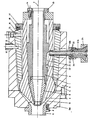
- the drawing shows a cross section through the spray head of an extruder system according to the invention.
- the spray head shown in the drawing is fixed, an extruder not shown in the drawing is also fixed and a second extruder not shown in the drawing is arranged in the direction transverse to axis 7 of the spray head displaceable and lockable extruder.
- the spray head shown in the drawing consists of a central mandrel 1, through the central bore of which the strand-like product to be encased is passed from right to left, a central, also hollow mandrel 2, which is arranged essentially concentrically to the axis 7 and is mounted on the tubular guide piece 3 by means of the spherical joint surfaces 4, and from the likewise tubular base body 5, which is firmly connected to the machine frame and surrounds the guide piece 3.
- These mandrels shaped like nozzles and a shoulder 5A on the base body 5 are closed by a mouthpiece 6 which is fastened to the base body 5 by means of screws 8 on the shoulder 5A.
- a material guide channel 9 with an annular cross-section is formed, which is fed from an extruder via special connecting pieces which form the material feed pipe 10.
- a further material guide channel 11 is formed, which is fed through a connecting piece in the form of the material supply pipe 12 via the material distribution channel 13.
- the cable core is fed through the central mandrel 1 and first receives a thin layer of a semiconductor which is fed and applied through the material guide channel 9 and then immediately afterwards a thicker cladding layer, the material of which is fed through the material guide channel 11.
- the middle mandrel 2 can be pulled out of the ball joint 4 as soon as the mouthpiece 6 and the front part 5A of the base body 5 have been removed. So that the central mandrel is firmly connected in the central mandrel 1 after adjustment of the material guide channel 9, screws 14 are screwed into the rear (right) end face of the central mandrel, which are located on the rear of the central nozzle Support the flange 15 attached to the front.
- the middle mandrel 2 is adjusted with respect to the base body 5 and thus with respect to the frame by means of adjusting screws 16, which are screwed into the guide piece 3 with a thread and with their end faces lie laterally against the middle mandrel 2.
- a seal to the rear takes place in that the middle mandrel 2 carries at its end a flange 17 in which a spring-loaded preload ring 18 is resiliently mounted in an annular recess, which presses against the end face of the guide piece 3 designed as a spherical cap ring surface and thereby the sealing causes.
- the sheathing material is fed into the material guide channel 9 with an annular cross-section via the material distribution channel 20, which is connected to the material feed pipe 10 via the flow channel 21.
- the material feed pipe part 10A is screwed into a threaded hole in the central mandrel 2 by means of a screw thread.
- the material supply pipe section 10A is provided with a spherical cap-like extension 22, in whose inner hollow spherical cap ring surface the end piece of the material supply pipe section 10B, which is also spherical cap-shaped, engages and rests.
- the end of the material feed pipe section 10B is provided with a thread onto which a screw connection 24 is screwed, the inside is provided with a hollow spherical cap ring surface 24 and covers the spherical cap-like extension 22.
- the spherical cap-like end extension of the pipe section 10B is fastened to the extruder with a screw connection 25.
- Channels for a tempering medium which are not shown, can be accommodated within the mandrels 1, 2, the guide piece 3 and the base body 5, as well as its extension 5A.
- a component with one or more further material supply channels is attached to the base body 5 or its extension 5A.
Abstract
Description
Die Erfindung betrifft eine Extruderanlage mit einem Spritzkopf zum Ummanteln eines strangförmigen Produktes, insbesondere eines Kabels, mit mehreren unmittelbar nacheinander aufgebrachten Schichten aus Kunststoff und/oder Kautschuk und/oder deren Mischungen, bei der der Spritzkopf auf einem Maschinengestell montiert ist und bei der zu den Seiten des Spritzkopfes Extruder angeordnet sind, die über spezielle Anschlußstücke, Zuführrohrleitungsstücke oder dergl. an den Spritzkopf angeschlossen sind, und bei der der Spritzkopf aus einem zentralen hohlen Dorn, durch die das zu ummantelnde Produkt geführt ist und aus mehreren, im wesentlichen konzentrisch zur dieser angeordneten, Ausformdüsen bildenden Spritzwerkzeugen in Form von Dornen und/oder Leitstücken besteht, die zwischen sich im Querschnitt ringförmige mit ihrem einen Ende die Ausformdüsen bildenden Kanäle einschließen, deren anderes Ende jeweils über die Zufuhrrohrleitungsstücke an einen Extruder angeschlossen ist.The invention relates to an extruder system with a spray head for sheathing a strand-like product, in particular a cable, with a plurality of layers of plastic and / or rubber and / or mixtures thereof applied immediately one after the other, in which the spray head is mounted on a machine frame and in which the Sides of the spray head are arranged extruders which are connected to the spray head via special connecting pieces, feed pipe pieces or the like, and in which the spray head consists of a central hollow mandrel through which the product to be encased is guided and of several, essentially concentric to the latter arranged, forming die-forming injection molds in the form of thorns and / or guide pieces, which enclose between them in cross-section annular channels with one end forming the die, the other end of which is connected via the feed pipe pieces to an extruder.
Auf einer derartigen Extruderanlage werden Kabel hergestellt, deren Seele durch die Bohrung des zentralen Dornes geführt ist und anschließend zuerst mit einer dünnen Halbleiterschicht und später mit einer starken Isolationsschicht aus nichtleitendem Kunststoff umgeben wird. Bei dieser Extruderanlage sind die einzelnen die Ausformdüsen bildenden Dorne bzw. Leitstücke exakt zentrisch feststehend angeordnet. Die auf dieser Extruderanlage hergestellten Kabel entsprechen hinsichtlich den Toleranzen der Ummantelung nicht modernen, an ein Hochspannungskabel zu stellenden Anforderungen. Die Stärke der Ummantelungen ist nämlich ringsum die Seele herum nicht gleichmäßig genug.In such an extruder system cables are produced, the core of which is guided through the bore of the central mandrel and is then surrounded first with a thin semiconductor layer and later with a strong insulation layer made of non-conductive plastic. In this extruder system, the individual mandrels or guide pieces forming the shaping nozzles are arranged in an exactly central, fixed manner. The cables produced on this extruder system do not meet the modern requirements for a high-voltage cable with regard to the tolerances of the sheathing. The thickness of the sheathing is not uniform enough around the soul.
Es sind auch Extruderanlagen bekannt geworden, bei denen die als Düsen ausgebildeten Dorne geteilt sind und die Endstücke, quer zur Achsrichtung verschiebbar angeordnet sind. Diese Extruderanlage ist aus der FR-A-2 492 729 bekannt. Durch eine Verschiebung der Dorn-Endstücke während des Betriebes läßt sich zwar das Kabel in seine Toleranzen der Ummantelungsschichten besser einstellen, das erzeugte Kabel hat aber insbesondere in der Halbleiterschicht immer wieder Fehlerstellen. Diese sind darauf zurückzuführen, daß an der Verschiebestelle der Dorn-Endstücke im Betrieb zu extrudierendes Material stehenbleibt, das hier anfängt, sich zu vernetzen bzw. zu vulkanisieren und das dann während des Betriebes von Zeit zu Zeit von dem strömenden Material mitgenommen wird und wegen der bereits fortgeschrittenen Vernetzung bzw. Vulkanisation die Fehlerstellen in der Isolier- oder Halbleiterschicht bildet. Derartige Fehlerstellen müssen aus dem Kabel herausgeschnitten werden, was zu erheblichen Verlusten führt, weil nicht nur die Fehlerstelle selbst, sondern auch benachbarte Bereiche meist mit weggeschnitten werden müssen. Die erhaltenen kürzeren Kabelstücke sind oft auch von geringem Wert, wenn sie durch das Ankoppeln eines weiteren Kabelstückes verlängert werden müssen.Extruder systems have also become known in which the mandrels designed as nozzles are divided and the end pieces are arranged such that they can be displaced transversely to the axial direction. This extruder system is known from FR-A-2 492 729. By shifting the mandrel end pieces during operation, the cable can be adjusted better in its tolerances of the sheathing layers, but the cable produced always has flaws, particularly in the semiconductor layer. These are due to the fact that material to be extruded remains at the displacement point of the mandrel end pieces during operation, which begins to cross-link or vulcanize here, and which is then taken during operation from time to time by the flowing material and because of the already advanced networking or vulcanization the flaws in the insulating or semiconductor layer forms. Such flaws have to be cut out of the cable, which leads to considerable losses, because not only the flaw itself, but also adjacent areas usually have to be cut away. The shorter pieces of cable obtained are often of little value if they have to be extended by coupling another piece of cable.
Ein Spritzkopf für eine Zweischichtenummantelung ist aus der Literaturstelle SOVIET INVENTIONS ILLUSTRATED bekannt geworden. Bei dieser Extrusionsanlage sind die beiden Extruder auf einer Seite des Spritzkopfes angeordnet, was es erforderlich macht, daß zwischen den beiden Extrudern und dem Spritzkopf ein Übergangsstück mit zwei schräg zueinander verlaufenden Kanälen vorzusehen ist. Die Zuführung des aus dem einen Extruder kommenden und inneren Ummantelungsschlauch geführten Extrudates erfolgt am Rande einer Kugelkalotte des im Spritzkopf angeordneten Kugelgelenkes, welches sich teilweise in den Weg des vom Extruder kommenden Extrudates einschiebt. Die ringförmige Verteilung des extrudierten Materials aus dem Zuführungskanal am Rande dieser Kugelkalotte ist ungünstig, weil hier das Material bei der Verteilung über den großen Durchmesser der Kugelkalotte langsam fließt und im Fließschatten stehenbleiben, vulkanisieren bzw. vernetzen kann und dadurch Inhomogenitäten bilden kann, die das Extrudat Ausschuß werden lassen.A spray head for a two-layer coating has become known from the SOVIET INVENTIONS ILLUSTRATED reference. In this extrusion system, the two extruders are arranged on one side of the spray head, which makes it necessary to provide a transition piece with two channels running obliquely to one another between the two extruders and the spray head. The extrudate coming from the inner jacket of an extruder is fed in at the edge of a spherical cap of the ball joint arranged in the extrusion head, which partially slides into the path of the extrudate coming from the extruder. The ring-shaped distribution of the extruded material from the feed channel at the edge of this spherical cap is unfavorable, because here the material flows slowly over the large diameter of the spherical cap and can remain in the flow shadow, vulcanize or crosslink and can thus form inhomogeneities that the extrudate To be rejected.
Durch die US-A-36 92 447 ist es bekannt, in einem Zuführungskanal von einem Extruder zu einem Spritzkopf ein bewegliches Kanalstück mit zwei Kugelgelenken anzuordnen. Bei schlechter Extruderausvichtung besteht die Gefahr von Auvulkanisatieren im Fließweg aus den Gelenksstellen.From US-A-36 92 447 it is known to arrange a movable channel piece with two ball joints in a feed channel from an extruder to a spray head. If the extruder is poorly aligned, there is a risk of vulcanization in the flow path from the articulation points.
Die Erfindung vermeidet diese Nachteile. Es ist die Aufgabe der Erfindung, eine Extruderanlage mit einem hochgenau ummantelnden Spritzkopf zu schaffen, der während des Betriebes einstellbar und nachstellbar ist und der so gestaltet ist, daß in den Fließwegen des zu extrudierenden Materiales Materialansammlungen nicht hängenbleiben und bereits im Fließweg vulkanisieren oder vernetzen.The invention avoids these disadvantages. It is the object of the invention to provide an extruder system with a high-precision encasing spray head which is adjustable and adjustable during operation and which is designed in such a way that material accumulations do not get caught in the flow paths of the material to be extruded and vulcanize or crosslink already in the flow path.
Die Erfindung besteht darin, daß der den zentralen Dorn nächst umgebende mittlere Dorn in einem kugelkalottenflächen aufweisenden Gelenk verschwenkbar und feststellbar gelagert ist, und daß in den mittleren Dorn seitlich ein erstes Zulaufrohrstück fest eingebaut ist, welches mit dem zugeordneten Extruder über mindestens ein weiteres Zulaufrohrstück verbunden ist, wobei das erste Zulaufrohrstück mit dem nächsten und dieses oder ein nachfolgendes mit dem Extruder über Gelenke mit Kugelkalotten aufweisenden Flächen verbunden ist.The invention consists in the fact that the central mandrel surrounding the central mandrel is pivotably and fixably mounted in a joint having spherical cap surfaces, and that a first inlet pipe piece is firmly installed laterally in the central mandrel, which is connected to the associated extruder via at least one further inlet pipe piece is, the first inlet pipe piece is connected to the next and this or a subsequent one with the extruder by means of joints with spherical caps.
Ein derartiges Gelenk mit kugelkalottenflächen läßt sich derart gestalten, daß keine Taschen oder Vorsprünge gebildet sind, an denen oder hinter de nen Materialansammlungen außerhalb des Fließweges des zu extrudierenden Materials stehen bleiben. Mit der Anwendung eines derartigen Kugelgelenkes ist jedoch der erfindungsgemäße technische Erfolg nicht allein erreichbar, es muß auch das Materialzuführungsrohr so gestaltet sein, daß hier kein zu extrudierendes Material stehen- oder hängenbleibt. Das ist bei dieser Extruderanlage erreicht.Such a joint with spherical cap surfaces can be designed such that no pockets or projections are formed, on which or behind de Native material accumulations remain outside the flow path of the material to be extruded. With the use of such a ball joint, however, the technical success according to the invention cannot be achieved on its own; the material feed pipe must also be designed in such a way that no material to be extruded remains or sticks here. This has been achieved with this extruder system.
Zweckmäßig ist es, wenn der mittlere Dorn in ein hohl ausgebildetes Leitstück eingeschoben ist, das an seinem Ende das mit Kugelkalottenflächen gebildete Gelenk trägt, um eine baulich einfache Lösung zu haben, bei der der mittlere Dorn für Reinigungszwecke in Extrusionsrichtung herausgezogen werden kann.It is expedient if the central mandrel is inserted into a hollow guide piece which carries at its end the joint formed with spherical cap surfaces in order to have a structurally simple solution in which the central mandrel can be pulled out in the extrusion direction for cleaning purposes.
Vorteilhaft ist es, wenn der Grundkörper an seinem Ende eine ringförmige Kugelkalottenfläche aufweist, gegen die ein am Ende des mittleren Dornes gelagerter auch als Dichtung wirkender Vorspannring gepreßt ist. Über den Ring wird die Vorspannung erreicht, die die Kugelkalotte in die Lagerschale preßt und damit verhindert, daß im Anfahrzustand Masse zwischen diese Flächen dringt. Die Fläche zwischen dem Leitstück und dem Anpreßring ist als Kalotte ausgebildet, damit bei Verstellung gleichbleibende Verhältnisse vorliegen.It is advantageous if the base body has at its end an annular spherical cap surface against which a prestressing ring, which also acts as a seal and is supported at the end of the central mandrel, is pressed. The preload is achieved via the ring, which presses the spherical cap into the bearing shell and thus prevents mass from penetrating between these surfaces in the start-up state. The surface between the guide piece and the pressure ring is designed as a spherical cap so that constant conditions are present when the adjustment is made.
Eine einfache Einstellmöglichkeit wird dadurch erreicht, daß im Grundkörper mindestens drei am mitt leren Dorn anliegende Verstellschrauben angeordnet sind.An easy adjustment is achieved in that in the base body at least three am Leren thorn adjuster screws are arranged.
Weiterhin ist es vorteilhaft für eine günstige Einstellmöglichkeit, wenn der zentrale Dorn gegenüber dem Maschinengestell und gegenüber dem ihn umgebenden mittleren Dorn verschwenkbar und feststellbar ist. In den Dorn kann eine Kalotte in ähnlicher Weise eingebracht werden. Damit kann die innen aufzubringende Schicht genau eingestellt werden. Ein besonderer Vorteil ist, daß bei Verstellung des mittleren Dornes der Materialführungskanal nicht verändert wird.Furthermore, it is advantageous for a favorable setting option if the central mandrel can be pivoted and locked relative to the machine frame and with respect to the central mandrel surrounding it. A calotte can be introduced into the mandrel in a similar manner. This means that the layer to be applied on the inside can be adjusted precisely. A particular advantage is that the material guide channel is not changed when the central mandrel is adjusted.
Sollten noch weitere Ummantelungsschichten vorgesehen werden, so sind diese meist dünn und bei ihnen ist der Materialfluß nicht so problematisch wie bei den inneren aufzubringenden Schichten. Daher ist es zweckmäßig, wenn weiter außen angeordnete weitere Rohrstücke von Ausformdüsen gegenüber den inneren Dornen und dem Grundkörper senkrecht zu deren Achsrichtung verschiebbar und feststellbar angeordnet sind.If additional sheathing layers are provided, these are usually thin and the material flow is not as problematic for them as for the inner layers to be applied. It is therefore expedient if further pipe pieces of shaping nozzles arranged further outside are arranged such that they can be displaced and locked perpendicularly to their axial direction with respect to the inner mandrels and the base body.
Damit die Zulaufrohrleitung sich bei einer Einstellung des zweiten Düsenrohrstückes frei bewegen kann, ist es zweckmäßig, wenn im Grundkörper an der Stelle des Materialzuführungsrohres ein Loch von größerem Durchmesser als dem Durchmesser des Materialzuführungsrohres vorgesehen ist.So that the inlet pipeline can move freely when the second nozzle pipe section is set, it is expedient if a hole of a larger diameter than the diameter of the material supply pipe is provided in the base body at the location of the material supply pipe.
Um dem zweiten Düsenrohrstück nach der Einstellung einen festen Sitz zu geben, ist es zweckmäßig, wenn der zentrale Dorn an seinem Ende einen Flansch trägt, durch dessen Löcher in den mittleren Dorn endseitig achsparallel eingeschraubte Schrauben hindurchgreifen.In order to give the second nozzle tube piece a firm fit after adjustment, it is useful if the central mandrel carries a flange at its end, through which holes in the central mandrel end screws that are axially parallel.
Dabei ist es für eine gute Zuführung des Materials zweckmäßig, wenn zwischen dem Zuführrohrstück und dem das zu extrudierende Material in den Düsenspalt des Materialzuführungskanales einführenden Materialverteilkanal ein achsparalleler Fließkanal angeordnet ist.It is expedient for a good supply of the material if an axially parallel flow duct is arranged between the feed pipe piece and the material distribution duct introducing the material to be extruded into the nozzle gap of the material supply duct.
Das Wesen der vorliegenden Erfindung ist nachstehend anhand eines in der Zeichnung schematisch dargestellten Ausführungsbeispieles näher erläutert. Die Zeichnung zeigt einen Querschnitt durch den Spritzkopf einer erfindungsgemäßen Extruderanlage.The essence of the present invention is explained below with reference to an embodiment shown schematically in the drawing. The drawing shows a cross section through the spray head of an extruder system according to the invention.
Auf einem Maschinengestell sind der in der Zeichnung dargestellte Spritzkopf fest, ein in der Zeichnung nicht dargestellter Extruder ebenfalls fest und ein in der Zeichnung weiter nicht dargestellter zweiter Extruder in Richtung quer zur Achse 7 des Spritzkopfes verschiebbarer und feststellbarer Extruder angeordnet.On a machine frame, the spray head shown in the drawing is fixed, an extruder not shown in the drawing is also fixed and a second extruder not shown in the drawing is arranged in the direction transverse to axis 7 of the spray head displaceable and lockable extruder.
Der in der Zeichnung näher dargestellte Spritzkopf besteht aus einem zentralen Dorn 1, durch dessen zentrale Bohrung das zu ummantelnde strangförmige Produkt von rechts nach links hindurchgeführt wird, einem mittleren, ebenfalls hohlem Dorn 2, welcher im wesentlichen konzentrisch zur Achse 7 angeordnet ist und auf dem rohrförmigen Leitstück 3 mittels der Kugelgelenkflächen 4 gelagert, sowie aus dem ebenfalls rohrförmigen Grundkörper 5, welcher fest mit dem Maschinengestell verbunden ist und das Leitstück 3 umgibt. Diese wie Düsen geformten Dorne und ein Ansatz 5A am Grundkörper 5 sind durch ein Mundstück 6 abgeschlossen, welches mittels Schrauben 8 am Ansatz 5A am Grundkörper 5 besfestigt ist. Zwischen dem zentralen Dorn 1 und dem mittleren Dorn 2 ist ein im Querschnitt ringförmiger Materialführungskanal 9 gebildet, der über spezielle Anschlußstücke, die das Materialzuführungsrohr 10 bilden, aus einem Extruder gespeist wird. Zwischen dem mittleren Dorn 2 und dem Grundkörper 5 ist ein weiterer Materialführungskanal 11 gebildet, welcher durch ein Anschlußstück in Form des Materialzuführungsrohres 12 über den Materialverteilkanal 13 gespeist wird. Bei der Kabelherstellung wird die Kabelseele durch den zentralen Dorn 1 zugeführt und erhält zuerst eine dünne Schicht eines Halbleiters, der durch den Materialführungskanal 9 zugeführt und aufgetragen wird und sodann unmittelbar daran anschließend eine stärkere Mantelschicht, deren Material durch den Materialführungskanal 11 zugeführt wird.The spray head shown in the drawing consists of a
Der mittlere Dorn 2 ist aus dem Kugelgelenk 4 herausziehbar, sobald das Mundstück 6 und der vordere Teil 5A des Grundkörpers 5 abgebaut sind. Damit der mittlere Dorn nach Einstellung des Materialführungskanales 9 fest in dem zentralen Dorn 1 verbunden ist, sind in die hintere (rechte) Stirnseite des mittleren Dornes Schrauben 14 eingeschraubt, die sich auf einen an der zentralen Düse an deren hinte rer Stirnseite angebrachten Flansch 15 abstützen.The
Eine Einstellung des mittleren Dornes 2 gegenüber dem Grundkörper 5 und damit gegenüber dem Gestell erfolgt durch Verstellschrauben 16, die mit einem Gewinde im Leitstück 3 eingeschraubt sind und mit ihrer Stirnseite seitlich an dem mittleren Dorn 2 anliegen.The
Eine Abdichtung nach hinten erfolgt dadurch, daß der mittlere Dorn 2 an seinem Ende einen Flansch 17 trägt, in welchem ein unter Federkraft stehender Vorspannring 18 in einer ringförmigen Ausnehmung federnd gelagert ist, der gegen die als Kugelkalottenringfläche ausgebildete endseitige Stirnfläche des Leitstückes 3 drückt und dadurch die Abdichtung bewirkt.A seal to the rear takes place in that the
Die Zuführung des Ummantelungsmateriales in den Materialführungskanal 9 von ringförmigem Querschnitt erfolgt über den Materialverteilkanal 20, welcher über den Fließkanal 21 mit dem Materialzuführungsrohr 10 verbunden ist. Der Materialzuführungsrohrteil 10A ist mittels eines Schraubgewindes in ein Gewindeloch in dem mittleren Dorn 2 eingeschraubt. An seinem anderen Ende ist das Materialzuführungsrohrstück 10A mit einer kugelkalottenartigen Erweiterung 22 versehen, in deren innere Hohlkugelkalottenringfläche das ebenfalls kugelkalottenförmig ausgebildete Endstück des Materialzuführungsrohrstückes 10B eingreift und anliegt. Das Ende des Materialzuführungsrohrstückes 10B ist mit einem Gewinde versehen, auf welches eine Verschraubung 24 geschraubt ist, die innenseitig mit einer Hohlkugelkalottenringfläche 24 versehen ist und die kugelkalottenartige Erweiterung 22 überfaßt. In ähnlicher Weise ist mit einer Verschraubung 25 die kugelkalottenartige endseitige Erweiterung des Rohrstückes 10B am Extruder befestigt.The sheathing material is fed into the material guide channel 9 with an annular cross-section via the
Innerhalb der Dorne 1, 2, des Leitstückes 3 und des Grundkörpers 5, sowie seines Ansatzes 5A, können Kanäle für ein Temperiermedium untergebracht sein, die nicht gezeichnet sind.Channels for a tempering medium, which are not shown, can be accommodated within the
Falls weitere Ummantelungsschichten aufzubringen sind, wird anstelle des Mundstückes 6 ein Bauteil mit einem oder mehreren weiteren Materialzuführungskanälen an den Grundkörper 5 bzw. seinen Ansatz 5A angebaut.If further sheathing layers are to be applied, instead of the
Claims (9)
Priority Applications (1)
| Application Number | Priority Date | Filing Date | Title |
|---|---|---|---|
| AT87107303T ATE60544T1 (en) | 1986-05-26 | 1987-05-19 | EXTRUDER PLANT FOR SHEATHING A LINEAR PRODUCT, ESPECIALLY A CABLE. |
Applications Claiming Priority (2)
| Application Number | Priority Date | Filing Date | Title |
|---|---|---|---|
| DE3617652 | 1986-05-26 | ||
| DE19863617652 DE3617652A1 (en) | 1986-05-26 | 1986-05-26 | EXTRUDER SYSTEM FOR SHEATING A STRAND-SHAPED PRODUCT, ESPECIALLY A CABLE |
Publications (3)
| Publication Number | Publication Date |
|---|---|
| EP0250828A2 EP0250828A2 (en) | 1988-01-07 |
| EP0250828A3 EP0250828A3 (en) | 1989-03-08 |
| EP0250828B1 true EP0250828B1 (en) | 1991-01-30 |
Family
ID=6301650
Family Applications (1)
| Application Number | Title | Priority Date | Filing Date |
|---|---|---|---|
| EP87107303A Expired - Lifetime EP0250828B1 (en) | 1986-05-26 | 1987-05-19 | Extruder for coating wire products, in particular a cable |
Country Status (7)
| Country | Link |
|---|---|
| US (1) | US4770620A (en) |
| EP (1) | EP0250828B1 (en) |
| JP (1) | JPH0829558B2 (en) |
| AT (1) | ATE60544T1 (en) |
| DE (2) | DE3617652A1 (en) |
| FI (1) | FI84992C (en) |
| NO (1) | NO872081L (en) |
Families Citing this family (18)
| Publication number | Priority date | Publication date | Assignee | Title |
|---|---|---|---|---|
| CA1308531C (en) * | 1988-10-11 | 1992-10-13 | Manfred A. A. Lupke | Extrusion die assembly |
| DE3902270A1 (en) * | 1989-01-26 | 1990-08-02 | Guenter Dipl Ing Richter | METHOD AND DEVICE FOR THE DISCONTINUOUS PRODUCTION OF MULTILAYERED, COEXTRUDED, TUBULAR PREFORMINGS FROM THERMOPLASTIC PLASTIC |
| DE3911000A1 (en) * | 1989-04-05 | 1990-10-11 | Troester Maschf Paul | Apparatus for extruding rubber mixtures and/or plastics |
| JPH0716946B2 (en) * | 1989-05-26 | 1995-03-01 | 松下電工株式会社 | Method for producing epoxy resin molding material |
| US4946364A (en) * | 1989-05-31 | 1990-08-07 | Rcm, Ltd., Rubber Consulting & Machinery | Apparatus for manufacturing reinforced polymeric tubing |
| US5108683A (en) * | 1991-04-05 | 1992-04-28 | Vijay Anand | Apparatus and method for extruding single and multiple layers of plastic |
| DE4111228A1 (en) * | 1991-04-08 | 1992-10-15 | Wilhelm Hegler | DEVICE FOR PRODUCING PLASTIC TUBES |
| US5215698A (en) * | 1991-11-25 | 1993-06-01 | Americraft Machined Products, Inc. | Extrusion tool and method of extrusion coating |
| DE4142047C2 (en) * | 1991-12-19 | 2001-03-01 | Siemens Ag | Method for covering at least one optical waveguide with a protective layer and for attaching reinforcing elements |
| NL9400602A (en) * | 1994-04-15 | 1995-11-01 | Townsend Engineering Co | A method of manufacturing food strands with a protein molded sleeve and apparatus for carrying out the method. |
| DE19936823C2 (en) * | 1999-08-05 | 2003-06-26 | Hosokawa Bepex Gmbh | Nozzle carrier and device for extruding doughy masses |
| US6514341B1 (en) * | 2000-04-03 | 2003-02-04 | Avaya Technology Corp. | Method and apparatus for removing optical fiber |
| FR2874736B1 (en) * | 2004-08-27 | 2006-11-03 | Nexans Sa | DEVICE FOR MANUFACTURING AN ALVEOLED SHEATH AROUND A DRIVER |
| CN101365344A (en) * | 2006-02-07 | 2009-02-11 | Wm.雷格利Jr.公司 | Apparatus and method for preparing a multiple phase confectionery product |
| US20080095899A1 (en) * | 2006-10-13 | 2008-04-24 | Wm. Wrigley Jr. Company | Method and apparatus for producing a multiple phase, confectionery article |
| CN102708991A (en) * | 2012-05-10 | 2012-10-03 | 太仓戴尔塔精密模具有限公司 | Head of extruding machine |
| DE102018204729A1 (en) * | 2018-03-28 | 2019-10-02 | Raumedic Ag | Tool head for a hollow profile extruder |
| DE102020125261B3 (en) | 2020-09-28 | 2021-10-07 | Troester Gmbh & Co. Kg | Extrusion head and method for producing an elongated hollow body by means of this extrusion head |
Family Cites Families (17)
| Publication number | Priority date | Publication date | Assignee | Title |
|---|---|---|---|---|
| FR1096372A (en) * | 1953-02-25 | 1955-06-20 | British Insulated Callenders | Improvements to extruding devices |
| US3228356A (en) * | 1963-08-21 | 1966-01-11 | Schafer Leonhard | Unique die for extrusion of pastry |
| DE1629716C3 (en) * | 1967-09-29 | 1983-06-01 | Benteler-Werke Ag Werk Neuhaus, 4790 Paderborn | Method and device for the continuous application of a heat and sound insulating jacket layer on a metal pipe |
| US3538547A (en) * | 1968-04-26 | 1970-11-10 | Gen Electric | Extruder head for dual extrusion |
| DE1908933B2 (en) * | 1969-02-22 | 1971-04-29 | EXTRUSION HEAD FOR EXTRUSION OF A HOSE | |
| US3692447A (en) * | 1970-11-30 | 1972-09-19 | Crompton & Knowles Corp | Multiple extrusion apparatus |
| JPS51147556A (en) * | 1975-06-13 | 1976-12-17 | Toyo Soda Mfg Co Ltd | Multiilayer rotary circular die |
| US4116605A (en) * | 1976-04-26 | 1978-09-26 | Burrell John R | Apparatus for producing retreading envelopes |
| FI53522C (en) * | 1976-10-18 | 1978-05-10 | Nokia Oy Ab | FOERFARANDE FOER TILLVERKNING AV HOEGSPAENNINGSPLASTKABEL |
| NL7708676A (en) * | 1976-11-08 | 1978-05-10 | Kobe Steel Ltd | DEVICE FOR COVERING STEEL PIPES, METHOD FOR COVERING STEEL PIPES AND COATED STEEL PIPES THIS OBTAINED. |
| SU863391A1 (en) * | 1979-05-14 | 1981-09-15 | Экспериментально-Конструкторский И Технологический Институт | Extrusion head for making polymeric bag film |
| FR2492729A1 (en) * | 1980-10-27 | 1982-04-30 | Telecommunications Sa | Twin extruder system for covering electric cables - with independent transverse linear alignment of the die for the outer coating |
| FR2515411A1 (en) * | 1981-10-28 | 1983-04-29 | Telecommunications Sa | METHOD AND DEVICE FOR MANUFACTURING A HELICOIDAL GROOVE JONC FOR OPTICAL FIBER CABLE AND THE JONC OBTAINED BY THE PROCESS |
| US4495022A (en) * | 1982-08-31 | 1985-01-22 | At&T Technologies, Inc. | Extrusion method and apparatus |
| FR2544874B1 (en) * | 1983-04-22 | 1985-06-14 | Cables De Lyon Geoffroy Delore | METHOD FOR MANUFACTURING AN OPTICAL FIBER CABLE, AND DEVICE FOR CARRYING OUT SAID METHOD |
| JPS60105521A (en) * | 1983-11-15 | 1985-06-11 | Hitachi Cable Ltd | Thickness deviation regulating device for cross head of extruder |
| US4551087A (en) * | 1984-06-11 | 1985-11-05 | Northern Telecom Limited | Extrusion apparatus |
-
1986
- 1986-05-26 DE DE19863617652 patent/DE3617652A1/en not_active Withdrawn
-
1987
- 1987-05-19 EP EP87107303A patent/EP0250828B1/en not_active Expired - Lifetime
- 1987-05-19 NO NO872081A patent/NO872081L/en unknown
- 1987-05-19 DE DE8787107303T patent/DE3767782D1/en not_active Expired - Fee Related
- 1987-05-19 AT AT87107303T patent/ATE60544T1/en not_active IP Right Cessation
- 1987-05-20 FI FI872226A patent/FI84992C/en not_active IP Right Cessation
- 1987-05-26 JP JP62129568A patent/JPH0829558B2/en not_active Expired - Lifetime
- 1987-05-26 US US07/054,304 patent/US4770620A/en not_active Expired - Fee Related
Also Published As
| Publication number | Publication date |
|---|---|
| FI872226A (en) | 1987-11-27 |
| ATE60544T1 (en) | 1991-02-15 |
| NO872081D0 (en) | 1987-05-19 |
| EP0250828A2 (en) | 1988-01-07 |
| FI84992B (en) | 1991-11-15 |
| DE3617652A1 (en) | 1987-12-03 |
| JPH0829558B2 (en) | 1996-03-27 |
| EP0250828A3 (en) | 1989-03-08 |
| US4770620A (en) | 1988-09-13 |
| DE3767782D1 (en) | 1991-03-07 |
| JPS6325015A (en) | 1988-02-02 |
| NO872081L (en) | 1987-11-27 |
| FI872226A0 (en) | 1987-05-20 |
| FI84992C (en) | 1995-02-21 |
Similar Documents
| Publication | Publication Date | Title |
|---|---|---|
| EP0250828B1 (en) | Extruder for coating wire products, in particular a cable | |
| DE3025597C2 (en) | Injection head for injection molding of multi-layer molded parts made of two different plastics that can be introduced from two separate injection cylinders | |
| EP0326584B1 (en) | Process and device for producing large hollow plastic bodies with multilayered walls | |
| EP0118692B1 (en) | Torpedo for the mandrel of a parison extruder head for the manufacture of tube segments or tubes of thermoplastic material | |
| DE1779315A1 (en) | Method and device for shaping a material, in particular by injection into a hollow mold | |
| DE2366041A1 (en) | CABLE CORES MANUFACTURING PROCESS | |
| DE1945675B2 (en) | PROCESS AND DEVICE FOR MANUFACTURING HOSES FROM RUBBER OR OTHER PLASTICIZABLE COMPOSITIONS WITH STRONG REINFORCING INSERTS IN THE HOSE LENGTH DIRECTION | |
| DE1921083A1 (en) | Spray nozzle for spraying a multilayer pipe or hose made of plastic | |
| DE1778471C3 (en) | Method and apparatus for producing a composite body by coextrusion | |
| EP0465889A2 (en) | Apparatus for manufacturing hollow thermoplastic bodies | |
| EP1661687A1 (en) | Extrusion die with die opening adjustment | |
| DE3902270A1 (en) | METHOD AND DEVICE FOR THE DISCONTINUOUS PRODUCTION OF MULTILAYERED, COEXTRUDED, TUBULAR PREFORMINGS FROM THERMOPLASTIC PLASTIC | |
| DE3026822A1 (en) | Uniform thermoplastic tubing - in which extruder feeds elbowed head with annular discharge ram which never interrupts continuous polymer flow | |
| DE2544879A1 (en) | MULTI-PIECE DISTRIBUTION HEAD FOR TRANSFERRING A RESIN FROM A RESIN SOURCE TO MULTIPLE INJECTION MOLDING NOZZLES | |
| DE2554239A1 (en) | Extrusion-coating an extruded plastics profiled blank - by coating it before final profiling and then shaping the semi-finished prod. into intended profile | |
| DE2911833C3 (en) | Straight die head for extruding two plastic pipes concentric to each other | |
| DE2220319A1 (en) | MULTIPLE PRESSING HEAD FOR EXTRUSION PRESSES FOR THE SIMULTANEOUS ENVELOPE OF SEVERAL ELECTRICAL CONDUCTORS OR CABLES | |
| DE2548670A1 (en) | Irrigation pipe with internal dripper units - having external helical grooves leading to pipe outlets | |
| EP0419983B2 (en) | Extrusion head for multi-layered extrudates | |
| DE1925460B2 (en) | Extruder head for the production of a multilayer tubular film from thermoplastics | |
| EP0595198B1 (en) | Apparatus and method for manufacturing elongated plastic profiles | |
| EP3479993B1 (en) | Ring distributor for an extruder head for manufacturing a hose-like moulded material made of thermoplastic material | |
| DE8614209U1 (en) | Extruder system for sheathing a strand-like product, in particular a cable | |
| DE3815298C2 (en) | ||
| DE3420944A1 (en) | Pelletising die for a synthetic resin extruder |
Legal Events
| Date | Code | Title | Description |
|---|---|---|---|
| PUAI | Public reference made under article 153(3) epc to a published international application that has entered the european phase |
Free format text: ORIGINAL CODE: 0009012 |
|
| AK | Designated contracting states |
Kind code of ref document: A2 Designated state(s): AT BE CH DE FR GB IT LI SE |
|
| PUAL | Search report despatched |
Free format text: ORIGINAL CODE: 0009013 |
|
| AK | Designated contracting states |
Kind code of ref document: A3 Designated state(s): AT BE CH DE FR GB IT LI SE |
|
| 17P | Request for examination filed |
Effective date: 19890404 |
|
| 17Q | First examination report despatched |
Effective date: 19891227 |
|
| GRAA | (expected) grant |
Free format text: ORIGINAL CODE: 0009210 |
|
| ITF | It: translation for a ep patent filed |
Owner name: DOTT. FRANCO CICOGNA |
|
| AK | Designated contracting states |
Kind code of ref document: B1 Designated state(s): AT BE CH DE FR GB IT LI SE |
|
| REF | Corresponds to: |
Ref document number: 60544 Country of ref document: AT Date of ref document: 19910215 Kind code of ref document: T |
|
| GBT | Gb: translation of ep patent filed (gb section 77(6)(a)/1977) | ||
| REF | Corresponds to: |
Ref document number: 3767782 Country of ref document: DE Date of ref document: 19910307 |
|
| ET | Fr: translation filed | ||
| PLBE | No opposition filed within time limit |
Free format text: ORIGINAL CODE: 0009261 |
|
| STAA | Information on the status of an ep patent application or granted ep patent |
Free format text: STATUS: NO OPPOSITION FILED WITHIN TIME LIMIT |
|
| 26N | No opposition filed | ||
| PGFP | Annual fee paid to national office [announced via postgrant information from national office to epo] |
Ref country code: SE Payment date: 19930512 Year of fee payment: 7 |
|
| PGFP | Annual fee paid to national office [announced via postgrant information from national office to epo] |
Ref country code: AT Payment date: 19930514 Year of fee payment: 7 |
|
| PGFP | Annual fee paid to national office [announced via postgrant information from national office to epo] |
Ref country code: FR Payment date: 19930527 Year of fee payment: 7 |
|
| PGFP | Annual fee paid to national office [announced via postgrant information from national office to epo] |
Ref country code: BE Payment date: 19930601 Year of fee payment: 7 |
|
| PG25 | Lapsed in a contracting state [announced via postgrant information from national office to epo] |
Ref country code: AT Effective date: 19940519 |
|
| PG25 | Lapsed in a contracting state [announced via postgrant information from national office to epo] |
Ref country code: SE Effective date: 19940520 |
|
| PG25 | Lapsed in a contracting state [announced via postgrant information from national office to epo] |
Ref country code: BE Effective date: 19940531 |
|
| BERE | Be: lapsed |
Owner name: PAUL TROESTER MASCHINENFABRIK Effective date: 19940531 |
|
| EUG | Se: european patent has lapsed |
Ref document number: 87107303.7 Effective date: 19941210 |
|
| PG25 | Lapsed in a contracting state [announced via postgrant information from national office to epo] |
Ref country code: FR Effective date: 19950131 |
|
| EUG | Se: european patent has lapsed |
Ref document number: 87107303.7 |
|
| REG | Reference to a national code |
Ref country code: FR Ref legal event code: ST |
|
| PGFP | Annual fee paid to national office [announced via postgrant information from national office to epo] |
Ref country code: GB Payment date: 19950511 Year of fee payment: 9 |
|
| PGFP | Annual fee paid to national office [announced via postgrant information from national office to epo] |
Ref country code: CH Payment date: 19950515 Year of fee payment: 9 |
|
| PGFP | Annual fee paid to national office [announced via postgrant information from national office to epo] |
Ref country code: DE Payment date: 19950517 Year of fee payment: 9 |
|
| PG25 | Lapsed in a contracting state [announced via postgrant information from national office to epo] |
Ref country code: GB Effective date: 19960519 |
|
| PG25 | Lapsed in a contracting state [announced via postgrant information from national office to epo] |
Ref country code: LI Effective date: 19960531 Ref country code: CH Effective date: 19960531 |
|
| GBPC | Gb: european patent ceased through non-payment of renewal fee |
Effective date: 19960519 |
|
| REG | Reference to a national code |
Ref country code: CH Ref legal event code: PL |
|
| PG25 | Lapsed in a contracting state [announced via postgrant information from national office to epo] |
Ref country code: DE Effective date: 19970201 |
|
| PG25 | Lapsed in a contracting state [announced via postgrant information from national office to epo] |
Ref country code: IT Free format text: LAPSE BECAUSE OF NON-PAYMENT OF DUE FEES;WARNING: LAPSES OF ITALIAN PATENTS WITH EFFECTIVE DATE BEFORE 2007 MAY HAVE OCCURRED AT ANY TIME BEFORE 2007. THE CORRECT EFFECTIVE DATE MAY BE DIFFERENT FROM THE ONE RECORDED. Effective date: 20050519 |