EP0250170B1 - Probensammler - Google Patents
Probensammler Download PDFInfo
- Publication number
- EP0250170B1 EP0250170B1 EP87305204A EP87305204A EP0250170B1 EP 0250170 B1 EP0250170 B1 EP 0250170B1 EP 87305204 A EP87305204 A EP 87305204A EP 87305204 A EP87305204 A EP 87305204A EP 0250170 B1 EP0250170 B1 EP 0250170B1
- Authority
- EP
- European Patent Office
- Prior art keywords
- container
- funnel
- vial
- coupled
- closing means
- Prior art date
- Legal status (The legal status is an assumption and is not a legal conclusion. Google has not performed a legal analysis and makes no representation as to the accuracy of the status listed.)
- Expired - Lifetime
Links
- 230000002093 peripheral effect Effects 0.000 claims description 8
- 239000013060 biological fluid Substances 0.000 abstract description 4
- 230000037431 insertion Effects 0.000 abstract 1
- 238000003780 insertion Methods 0.000 abstract 1
- 238000011109 contamination Methods 0.000 description 9
- 208000015181 infectious disease Diseases 0.000 description 8
- 206010036790 Productive cough Diseases 0.000 description 5
- 230000001681 protective effect Effects 0.000 description 5
- 210000003802 sputum Anatomy 0.000 description 5
- 208000024794 sputum Diseases 0.000 description 5
- 238000007789 sealing Methods 0.000 description 4
- HQTJHTMBKSOUFU-UHFFFAOYSA-N Andelin Natural products CC=C(C)/C(=O)OC1C(OC(=O)C=C(C)C)c2cc3C=CC(=O)Oc3cc2OC1(C)C HQTJHTMBKSOUFU-UHFFFAOYSA-N 0.000 description 3
- 238000000034 method Methods 0.000 description 3
- 229920000298 Cellophane Polymers 0.000 description 2
- 239000004698 Polyethylene Substances 0.000 description 2
- 210000001124 body fluid Anatomy 0.000 description 2
- 210000005069 ears Anatomy 0.000 description 2
- 230000013011 mating Effects 0.000 description 2
- -1 polyethylene Polymers 0.000 description 2
- 229920000573 polyethylene Polymers 0.000 description 2
- 230000007480 spreading Effects 0.000 description 2
- 238000009825 accumulation Methods 0.000 description 1
- 230000004888 barrier function Effects 0.000 description 1
- 239000008280 blood Substances 0.000 description 1
- 210000004369 blood Anatomy 0.000 description 1
- 230000008878 coupling Effects 0.000 description 1
- 238000010168 coupling process Methods 0.000 description 1
- 238000005859 coupling reaction Methods 0.000 description 1
- 238000003745 diagnosis Methods 0.000 description 1
- 201000010099 disease Diseases 0.000 description 1
- 208000037265 diseases, disorders, signs and symptoms Diseases 0.000 description 1
- 230000000694 effects Effects 0.000 description 1
- 239000012530 fluid Substances 0.000 description 1
- 239000000463 material Substances 0.000 description 1
- 230000007246 mechanism Effects 0.000 description 1
- 238000012986 modification Methods 0.000 description 1
- 230000004048 modification Effects 0.000 description 1
- 238000004806 packaging method and process Methods 0.000 description 1
- 230000008569 process Effects 0.000 description 1
- 239000012858 resilient material Substances 0.000 description 1
- 238000006467 substitution reaction Methods 0.000 description 1
- 239000012780 transparent material Substances 0.000 description 1
- 208000011479 upper respiratory tract disease Diseases 0.000 description 1
- 210000002700 urine Anatomy 0.000 description 1
- 230000000007 visual effect Effects 0.000 description 1
Images

Classifications
-
- A—HUMAN NECESSITIES
- A61—MEDICAL OR VETERINARY SCIENCE; HYGIENE
- A61B—DIAGNOSIS; SURGERY; IDENTIFICATION
- A61B10/00—Instruments for taking body samples for diagnostic purposes; Other methods or instruments for diagnosis, e.g. for vaccination diagnosis, sex determination or ovulation-period determination; Throat striking implements
- A61B10/0045—Devices for taking samples of body liquids
- A61B10/0051—Devices for taking samples of body liquids for taking saliva or sputum samples
-
- A—HUMAN NECESSITIES
- A61—MEDICAL OR VETERINARY SCIENCE; HYGIENE
- A61B—DIAGNOSIS; SURGERY; IDENTIFICATION
- A61B90/00—Instruments, implements or accessories specially adapted for surgery or diagnosis and not covered by any of the groups A61B1/00 - A61B50/00, e.g. for luxation treatment or for protecting wound edges
- A61B90/90—Identification means for patients or instruments, e.g. tags
Definitions
- the present invention is directed to medical and laboratory equipment, more specifically, to an apparatus for collecting biological fluids.
- apparatus used in the collection of biological fluids, specifically sputum include a vial held upright in a base with a funnel inserted in the vial open end.
- the apparatus disclosed in the Andelin et al. patent reference includes a specimen receptacle or vial, in which a funnel is inserted, coaxially disposed in an outer protective body which is made of a rigid material.
- a receptacle or vial cap is held in place within the protective body by four ribs integrally formed in the inner surface of this protective body. This cap is physically handled when being removed from mounting upon the vial.
- the vial and cap may be protected from contamination during the actual specimen collection, there exists the potential for contaminating the specimen and the possible spread of infection during the procedure of sealing the vial with the cap.
- the apparatus disclosed in the Schlesinger et al. patent reference includes a vial, in which a funnel is inserted, supported upright in a base.
- a flexible outer protective covering is provided surrounding both the vial and the base, in comparison to the rigid body disclosed in the Andelin et al. patent reference. Again, the vial cover is physically handled during the sealing operation which creates the potential of specimen contamination or the spread of infection.
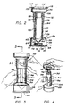
- the apparatus in Figure 6, includes a hollow, frustum-shaped base 12, having a pair of support ears 14 and 16 extending laterally outward therefrom, in which a vial 18 is inserted.
- a funnel 20 is fitted into the opening of the vial 18, with a cap 22 attached directly to the base 12, typically by being stapled in a cellophane bag 24 to one of the support ears 14 or 16. Again, the cap 22 must be physically handled as it is removed from the cellophane bag 24 and secured to the open end of the vial 18.
- FIG 7 another presently known collecting apparatus is seen at 44.
- This apparatus 44 includes a base 46, in which the specimen tube 48 is held in an upright position with a funnel 58 inserted in the tube 48 open end.
- the base 46 is substantially hollow and opened at its lower end.
- a detachable cover 45 is mounted at the base open end.
- a tube cap 50 is mounted inside the base 46 between three inwardly projecting ribs.
- the present invention accomplishes the foregoing objectives by providing an apparatus for collecting bodily fluids, particulary sputum.
- the collection apparatus of the invention generally includes a base stand which supports a specimen vial in an upright position. A funnel is inserted into the open end of the specimen vial.
- the base portion is a substantially hollow tubular structure to which a graspable lid is detachably secured.
- a vial cap is housed by this lid and positioned internally in the base portion when the lid is attached thereto. This lid is dimensioned to be grasped by and allow the user to secure the cap to the specimen vial without actually touching the cap.
- a specimen collecting apparatus comprising: a substantially elongated tubular container having a first closed end and a second open end; collection means which is removably secured to said container second open end for directing said specimen into said container; closing means formed to releasably close said container open end after removal of said collection means; means for supporting said container with or without said collection means in a substantially upright position; and container gripping means which extends up from said supporting means about said container formed to releasably grip said container; characterised in that said container gripping means partially surrounds said container and includes two substantially arcuately shaped walls which extend upwards from said supporting means to at least partially enclose said container, said upwardly extending walls being deflectable towards and back away from each other to allow said container to be gripped, whereby said container is held in said supporting means when said collection means is removed therefrom and/or when said closing means is coupled and/or removed from said container.
- the container supporting means is a substantially hollow tubular base stand.
- the upper end of this base stand is partially closed and formed to provide a receptacle in which a conical specimen vial can be placed and held in an upright position.
- a funnel is partially inserted in the open upper end of the vial.
- the fit of the funnel in the vial is firmer than the fit of the vial in the base. This allows the vial to be removed from the base by pulling up on the funnel.
- the funnel is formed with a neck portion which surrounds and encloses the upper portion of the vial.
- the base stand lower end is substantially open and to which the lid housing the vial cap is detachably coupled.
- the two upwardly extending arcuately shaped walls in combination with the preferred funnel neck portion, fully enclose the vial and minimize the possibility of any specimen becoming lodged on the vial outer surface. This reduces the risk of spreading any infection to anyone who subsequently handles the vial. By compressing these walls the appropriate personnel are able to grip the vial during the removal of the funnel and the attachment and/or removal of the cap, without touching the outer vial surface.
- the upwardly extending substantially arcuately shaped walls are spatially separated from each other along their lengths to allow for the visual observation of a graduation scale longitudinally provided on the vial and the amount of the specimen being collected.
- the present invention is directed to a specimen collecting apparatus having a base stand in which a specimen vial is held in a substantially upright position.
- a funnel is fitted partly into the vial open end.
- the base stand in conjunction with a portion of the funnel, substantially encloses the vial, isolating the vial from the specimen being collected.
- a vial cap is housed on a lid which is detachable to and upon which the base stand rests. This lid is formed to be grasped by the user and also to hold the cap while coupling the cap to and/or releasing the cap from the vial, without the user having to touch the cap. This minimizes the potential of spreading infection to the medical personnel who handle the apparatus and of contaminating the specimen by the handling of the cap.
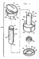
- the apparatus 26 includes a base stand 28, specimen vial 30 and funnel 32.
- the vial 30 is a substantially elongated hollow tube having a closed lower end 60 and an opposite open end 61. A portion of the funnel 32 can be inserted in the vial open end 61.
- the upper surface of the vial 30, contiguous to the open end 61, is formed with threads which are threadably mateable with a threaded vial cap 74.
- a graduation scale (usually a 50 millimeter graduation scale) is provided along the length of the vial 30, as indicated generally at 100.
- the base stand 28 is a substantially hollow tubular structure having a circular peripheral wall 36 and an upper wall 38.
- This upper wall 38 is provided with a receptacle 34 in which the vial 30 can be held in a subtantially upright position.
- a lid 40 is detachably coupled to the lower end 39 of the base stand 28 which is opened.
- This lid 40 is a substantially circular wall detachably coupled to the base stand 28 in any suitable manner.
- this lid 40 has a circular lip 66 which extends generally upward about the lid 40 periphery.
- the lip 66 is formed with an inwardly extending annular rib 68 that is spaced away from the surface of the lid 40 to define an annular groove 72.
- a mating rib 70 which is formed to extend out from the peripheral wall 36 about the lower end 39 can be placed in this groove 72.
- a user of the apparatus 26 places the base stand 28 into the lid 40 so that the ribs 68 and 70 become interlocked.
- either the base stand 28 or the lid 40 is comprised of a resilient material to allow the ribs 68 and 70 to deflect away from each other as the base stand 28 is placed onto the lid 40. This is but one mechanism allowing the base stand 28 and lid 40 to be repeatably coupled and decoupled.
- the lid 40 further includes a housing in which the vial cap 74 can be held, as indicated generally at 76.
- This housing 76 holds the cap 74 as it is coupled to and/or released from the vial 30 as the lid 40 is grasped by the patient or other personnel.
- the housing 76 is formed from a substantially ring-shaped enclosure 78 which extends generally upward from and is integral with the lid 40.
- the cap 74 is placed into this enclosure 78.
- the enclosure 78 is dimensioned to snugly fit the cap 74 and has an inner surface 79 which is formed to grip the outer peripheral surface of the cap 74, as the cap 74 is secured to and/or removed from the vial 30.
- these surfaces have cooperatively mating transverse ribs and grooves which interlock to allow the enclosure 78 to frictionally grip the cap 74 as the cap is threaded to or removed from the vial 30.
- the cap 74 and the housing 76 are placed in the base stand 28. This ensures that the cap 74 is isolated and free from contamination during the collecting of the specimen.
- the base stand 28 upper wall 38 defines the receptacle 34 in which the lower closed end 60 of the vial 30 is placed.
- This receptacle 34 is defined by a peripheral wall 42 which has a lower end from which a shoulder 64 extends radially inward for a specified distance, thus forming an aperture 62.
- the lower end 60 of the specimen vial 30 can be placed in this receptacle 34 and partially pass through this aperture 62.
- the remaining portion of the vial 30 lower end 60 rests upon the shoulder 64.
- the receptacle 34 is dimensioned to snugly retain the vial 30 in a substantially vertical or upright position.
- the vial 30 is formed with a polygonal configured skirt extending down about the lower end 60. This allows the vial 30 to be free standing. This type of formed vial 30 would be receivable in the described receptacle 34.
- the base stand 28 further includes a substantially tubular enclosure 94 which extends upward from the wall 38 about the receptacle 34.
- This enclosure 94 partially surrounds and encloses a portion of the vial 30, as better seen in FIGURE 3.
- This enclosure 94 is formed by two opposing upwardly extending arcuately shaped walls 96 and 98. These walls 96 and 98 are spatially separated from each other along their lengths to define first and second longitudinally cutaways 102 and 104. These cutaways 102 and 104 run substantially the entire length of the enclosure 94.
- these walls 96 and 98 are elastically deflectable towards and back away from each other to allow the user of the apparatus 10 to grasp a specimen vial 30 which is positioned in the enclosure 94. Furthermore, the 50 ml graduation scale 100, and the contents of the collection tube 30, can be observed through either of these cutaways 102 and 104. Furthermore, the enclosure 94 may be comprised of a transparent material.
- a specimen e.g. sputum
- the funnel 32 is formed with a tapered passageway 108 which longitudinally traverses the funnel 32 from a first larger funnel opening 109 to a second smaller funnel opening 110.
- the lower portion of the funnel 32 includes a neck portion 112. This neck portion 112 is dimensioned to be snugly fit in the open end 61 of the vial 30.
- the second smaller funnel opening 110 is provided at the lower end of the neck portion 112.
- a detachable cover 114 is provided to seal the open end 109 of the funnel 32. This cover 114 can be lifted off the funnel 32 when it is desired to introduce a specimen through the passageway 108 into the vial 30.
- this cover 114 is attached to the funnel 32 by a hinge 115.
- the cover 114 is formed as a cup-shaped body 117, which is dimensioned to be snugly fit in the passageway 108 contiguous to the open end 109.
- This cup-like body 117 has an outwardly extending flange 119 which is nested down upon the funnel 32 when the body 117 is positioned in the passageway 108.
- the funnel 32 also includes a substantially tubular sleeve 116 which extends downwards, substantially coaxial with the passageway 108, about the neck portion 112. This defines an annular area 118 between the tubular sleeve 116 and neck portion 112 in which the upper portion of the vial 30 can be placed.
- this sleeve 116 extends sufficiently downward to enclose at least the upper part of the tubular enclosure 94. In this manner, the specimen vial 30 is substantially enclosed by the combination of the enclosure 94 and the tubular sleeve 116. This provides a protective barrier about the vial 30 to minimize the accumulation on the exterior vial surface 30 of any specimen. This reduces the potential of transmitting infection to those who handle the vial 30.
- the procedure for collecting specimen and for sealing the vial 30 in accordance with an embodiment of the invention will now be described in detail.
- the fully assembled apparatus 26, with the funnel 32 inserted in the vial 30, is provided in a sealed container, not shown.
- This sealed container minimizes contamination of the apparatus 26 in transit, and is typically a polyethylene bag or enclosure.
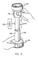
- the patient or appropriate medical personnel dislodges the vial 30, with the funnel 32 in place, from the base stand 28. This is accomplished, as illustrated in FIGURE 5, by grasping the funnel 32 about the tubular sleeve 116 with one hand, holding the base stand 28 down with the other handle and lifting the combined vial 30 and funnel 32 assembly out of the base stand 28.
- the removal of the vial 309 and funnel 32 in the manner described is facilitated by providing that the fit of the funnel 32 in the vial 30 is tighter than the fit of the vial 30 in the base stand receptacle 34. That is, when the user pulls up on the funnel 32, while holding down the base 28, the vial 30 will more easily be dislodged from the base stand 28 than the funnel 32.
- the vial 30 with the funnel 32 have been removed from the base stand 28 an appropriate marking is provided on the vial 30 outer surface to indicate the identity of the patient.
- a self-adhering label 120 is provided with the assembled apparatus 26 in the polyethylene bag or enclosure.
- the vial 30 and funnel 32 assembly is reinserted in the base stand receptacle 34.
- an appropriate medical personnel will carry out this step of the specimen-collecting operation.
- the patient or appropriate medical personnel then lifts the cover 114 off from the funnel 32.
- a specified amount of specimen is delivered into the specimen vial 30 through the passageway 108 of the funnel 32.
- the patient or appropriate medical personnel removes and disposes of the funnel 32.
- the user will grasp the vial 30, by compressing the two walls 96 and 98 inward, to retain the vial 30 in the base stand receptacle 34.
- the funnel 32 is grasped about the tubular sleeve 116 to minimize any potential contact with any specimen which may be found on the funnel 32 and/or to minimize any contamination.
- the funnel 32 is removed by twisting the funnel 32 off while grasping the vial 30, again by compressing the walls 96 and 98 inwards.
- the lid 40 is then removed from the base stand 28 and used as a capping device for threadably secure the cap 74 to the specimen vial 30.
- the lid 40 is then pulled off the cap 74 and mounted back upon the base stand 28, in the manner described above. Again, the patient or medical personnel will grip the vial 30 as the cap 74 is threaded to the vial 30 by compressing the walls 96 and 98 towards each other.
Landscapes
- Health & Medical Sciences (AREA)
- Life Sciences & Earth Sciences (AREA)
- Surgery (AREA)
- Animal Behavior & Ethology (AREA)
- Hematology (AREA)
- Engineering & Computer Science (AREA)
- Biomedical Technology (AREA)
- Heart & Thoracic Surgery (AREA)
- Medical Informatics (AREA)
- Molecular Biology (AREA)
- Pulmonology (AREA)
- Pathology (AREA)
- General Health & Medical Sciences (AREA)
- Public Health (AREA)
- Veterinary Medicine (AREA)
- Sampling And Sample Adjustment (AREA)
- Investigating Or Analysing Biological Materials (AREA)
- Apparatus Associated With Microorganisms And Enzymes (AREA)
- Automatic Analysis And Handling Materials Therefor (AREA)
- Crystals, And After-Treatments Of Crystals (AREA)
- Mechanical Treatment Of Semiconductor (AREA)
- Investigating Or Analyzing Materials By The Use Of Ultrasonic Waves (AREA)
Claims (14)
- Probensammelvorrichtung, aufweisend:
einen im wesentlichen spitz zulaufenden, röhrenförmigen Behälter (30) mit einem ersten geschlossenen Ende (60) und einem zweiten offenen Ende (61);
eine Sammeleinrichtung (32), die abnehmbar mit dem zweiten offenen Ende (61) des Behälters verbunden ist, um die Probe in den Behälter (30) zu leiten;
eine Verschlußeinrichtung (74), die so ausgebildet ist, daß sie das offene Ende (61) des Behälters nach dem Entfernen der Sammeleinrichtung (32) wieder abnehmbar verschließt;
eine Einrichtung (28) zum Halten des Behälters (30), mit oder ohne Sammeleinrichtung (32), in einer im wesentlichen aufrechten Position; und
eine Behältereinspanneinrichtung (94), die sich von der Halteeinrichtung (28) nach oben über den Behälter (30) erstreckt und so ausgebildet ist, daß sie den Behälter (30) wieder abnehmbar einspannt;
dadurch gekennzeichnet, daß die Behältereinspanneinrichtung (94) den Behälter (30) teilweise umgibt und zwei im wesentlichen bogenförmige Wände (96, 98) aufweist, die sich von der Halteeinrichtung (28) nach oben erstrecken, um den Behälter (30) zumindest teilweise einzuschließen, wobei die sich nach oben erstreckenden Wände (96, 98) zueinander hin und voneinander weg biegbar sind, um das Einspannen des Behälters (30) zu gestatten, wodurch der Behälter (30) in der Halteeinrichtung (28) gehalten wird, wenn die Sammeleinrichtung (32) davon entfernt wird und/oder wenn die Verschlußeinrichtung (74) mit dem Behälter (30) verbunden und/oder davon entfernt wird. - Vorrichtung nach Anspruch 1, wobei die Sammeleinrichtung ein Trichter (32) mit offenen oberen und unteren Enden und einem Durchgangsweg (108) dazwischen ist, wobei der Trichter (32) einen im wesentlichen röhrenförmigen Halsteil (112) aufweist, der sich von dem unteren Ende nach unten erstreckt und ausreichend fest in das offene Ende (61) des Behälters paßt, um zu gestatten, daß der Behälter (30) von der Halteeinrichtung (28) durch Verwendung des Trichters (32) entfernt werden kann.
- Vorrichtung nach Anspruch 2, wobei der Trichter (32) außerdem eine im wesentlichen röhrenförmige Manschette (116) aufweist, die sich im wesentlichen koaxial mit dem Halsteil (112) nach unten erstreckt, wobei die Manschette (116) räumlich vom Halsteil (112) getrennt ist, um dazwischen die Aufnahme zumindest eines Teils des Behälters (30) zu gestatten.
- Vorrichtung nach Anspruch 3, wobei zumindest ein Teil der sich nach oben erstreckenden Wände (96, 98) zwischen der röhrenförmigen Manschette (116) und dem Trichterhalsteil (112) mit dem Behälter (30) anordbar ist.
- Vorrichtung nach den Ansprüchen 2, 3 oder 4, wobei der Trichter (32) außerdem eine Abdeckung (114) aufweist, die wieder abnehmbar mit dem Trichter (32) verbunden ist und in das obere offene Ende des Trichters (32) paßt.
- Vorrichtung nach einem der vorhergehenden Ansprüche, wobei die Halteeinrichtung (28) ein Körper ist, der einen Behälter (34) definiert, in den der Behälter (30) aufgenommen und in aufrechter Position gehalten wird, wobei der Körper (36/38) außerdem eine Aushöhlung (76) definiert, in der die Verschlußeinrichtung (74) zumindest teilweise positioniert ist, wenn die Anfaßeinrichtung (40) mit dem Körper (36/38) verbunden ist, und wobei die Sammeleinrichtung (32) ausreichend mit dem zweiten offenen Ende (61) des Behälters verbunden ist, um zu gestatten, daß der Behälter (30) aus dem Körperbehälter (34) durch Verwendung der Sammeleinrichtung (32) entfernt werden kann.
- Vorrichtung nach Anspruch 6, wobei die Anfaßeinrichtung eine im wesentlichen planare Wand (40) ist, die abnehmbar mit dem Körper (36/38) verbunden ist, wobei die Wand (40) eine Einfassung (78) zum Aufnehmen und Halten der Verschlußeinrichtung (74) aufweist, wenn die Verschlußeinrichtung (74) mit dem Behälter (30) verbunden wird und/oder davon entfernt wird, wobei die Wandeinfassung (78) und die Verschlußeinrichtung (74) sich in der Körperaushöhlung (76) befinden, wenn die Wand (40) mit dem Körper (36/38) verbunden ist.
- Vorrichtung nach einem der vorhergehenden Ansprüche, wobei die Halteeinrichtung (28) einen im wesentlichen hohlen, röhrenförmigen Grundteil aufweist, definiert durch eine im wesentlichen kreisrunde periphere Wand (36) mit einem oberen Ende, das mit einer Wand (38) verbunden ist, in der ein Behälter (34) zum Aufnehmen und Festhalten des Behälters (30) in der im wesentlichen aufrechten Position ausgebildet ist, und einem unteren offenen Ende.
- Vorrichtung nach Anspruch 8, wobei die Anfaßeinrichtung eine im wesentlichen planare Wand (40) ist, die abnehmbar mit dem Grundteil am offenen Ende der peripheren Wand verbunden ist, wobei die planare Wand (40) eine Einrichtung zum Aufnehmen und Halten der Verschlußeinrichtung (74) aufweist, wenn die Verschlußeinrichtung (74) mit dem Behälter (30) verbunden wird und/oder davon entfernt wird, wobei die Gehäuseeinrichtung (78) außerdem die Verschlußeinrichtung (74) im Grundteil positioniert, wenn die planare Wand (40) mit dem Grundteil verbunden ist.
- Vorrichtung nach Anspruch 9, wobei die Gehäuse- und Halteeinrichtung eine im wesentlichen kreisrunde Einfassung (78) aufweist, die integral in der planaren Wand (40) ausgebildet ist, in der die Verschlußeinrichtung (74) Platz finden kann, wobei die kreisrunde Einfassung (78) eine Einrichtung zum Ankuppeln der in der kreisrunden Einfassung (78) positionierten Verschlußeinrichtung aufweist, wenn die Verschlußeinrichtung (74) mit dem Behälter (30) verbunden wird und/oder davon entfernt wird.
- Vorrichtung nach Anspruch 10, wobei die Verschlußeinrichtung ein im wesentlichen kreisrunder Deckel mit Gewinde (74) ist.
- Vorrichtung nach Anspruch 11, wobei zumindest ein Teil der planaren Wand (40) wesentlich größer in der Breite ist als die kreisrunde Einfassung (78), wodurch der größere Wandteil festgehalten wird, wenn die Verschlußeinrichtung (74) mit dem Behälter (30) verbunden wird und/oder davon entfernt wird.
- Vorrichtung nach Anspruch 10, 11 oder 12, wobei die planare Wand (40) im wesentlichen kreisrund ist und einen Durchmesser hat, der größer ist als der Durchmesser der kreisrunden Einfassung.
- Vorrichtung nach Anspruch 10, 11, 12 oder 13, wobei die Kupplungseinrichtung aufweist, daß die Einfassung der planaren Wand eine innere periphere Oberfläche hat, die so ausgebildet ist, daß sie die äußere periphere Oberfläche der Verschlußeinrichtung (74) kuppelt, wenn die Verschlußeinrichtung (74) mit dem Behälter (30) verbunden wird und/oder davon entfernt wird.
Priority Applications (1)
| Application Number | Priority Date | Filing Date | Title |
|---|---|---|---|
| AT87305204T ATE70178T1 (de) | 1986-06-16 | 1987-06-12 | Probensammler. |
Applications Claiming Priority (2)
| Application Number | Priority Date | Filing Date | Title |
|---|---|---|---|
| US06/874,766 US4741346A (en) | 1986-06-16 | 1986-06-16 | Speciman collector |
| US874766 | 1986-06-16 |
Publications (3)
| Publication Number | Publication Date |
|---|---|
| EP0250170A2 EP0250170A2 (de) | 1987-12-23 |
| EP0250170A3 EP0250170A3 (en) | 1988-11-30 |
| EP0250170B1 true EP0250170B1 (de) | 1991-12-11 |
Family
ID=25364535
Family Applications (1)
| Application Number | Title | Priority Date | Filing Date |
|---|---|---|---|
| EP87305204A Expired - Lifetime EP0250170B1 (de) | 1986-06-16 | 1987-06-12 | Probensammler |
Country Status (8)
| Country | Link |
|---|---|
| US (1) | US4741346A (de) |
| EP (1) | EP0250170B1 (de) |
| JP (1) | JP2525817B2 (de) |
| AT (1) | ATE70178T1 (de) |
| CA (1) | CA1270413A (de) |
| DE (1) | DE3775119D1 (de) |
| ES (1) | ES2028078T3 (de) |
| GR (1) | GR3003996T3 (de) |
Families Citing this family (43)
| Publication number | Priority date | Publication date | Assignee | Title |
|---|---|---|---|---|
| USD302470S (en) | 1986-06-20 | 1989-07-25 | Evergreen Industries, Inc. | Sputum collector |
| US5003988A (en) * | 1989-06-21 | 1991-04-02 | La Mina Ltd. | Modular multiple fluid sample preparation assembly |
| US4961432A (en) * | 1989-01-10 | 1990-10-09 | Cancer Diagnostics, Inc. | Modular fluid sample preparation assembly |
| US5024238A (en) * | 1989-01-10 | 1991-06-18 | Cancer Diagnostics, Inc. | Blood withdrawing apparatus and antigen testing method |
| US4920975A (en) * | 1989-02-21 | 1990-05-01 | Biomedical Polymers, Inc. | Biological fluid collection apparatus with the cap on the cover |
| US4932081A (en) * | 1989-08-11 | 1990-06-12 | Becton, Dickinson And Company | Sputum cup |
| US5283038A (en) * | 1990-12-18 | 1994-02-01 | Saliva Diagnostic Systems, Inc. | Fluid sampling and testing device |
| US5342328A (en) * | 1993-03-22 | 1994-08-30 | Grossman Michael D | Medical body fluid sampler device and method |
| USD436166S1 (en) | 1999-05-27 | 2001-01-09 | Sandy Berkey | Female urine specimen cup |
| USD425618S (en) * | 1999-08-06 | 2000-05-23 | Becton, Dickinson And Company | Specimen collection device |
| US7070053B1 (en) * | 2000-09-05 | 2006-07-04 | Cv Holdings Llc | System, method, and apparatuses for maintaining, tracking, transporting and identifying the integrity of a disposable specimen container with a re-usable transponder |
| US6467642B2 (en) | 2000-12-29 | 2002-10-22 | Patrick L. Mullens | Cryogenic shipping container |
| US6539726B2 (en) | 2001-05-08 | 2003-04-01 | R. Kevin Giesy | Vapor plug for cryogenic storage vessels |
| DE10145424B4 (de) * | 2001-09-14 | 2005-09-29 | Sarstedt Ag & Co. | Vorrichtung zur Durchführung eines Tests zum Nachweis von Partikeln im Urin |
| US7482116B2 (en) | 2002-06-07 | 2009-01-27 | Dna Genotek Inc. | Compositions and methods for obtaining nucleic acids from sputum |
| US20050059906A1 (en) * | 2003-09-12 | 2005-03-17 | Garry Tsaur | Specimen collector |
| US7282181B2 (en) * | 2004-09-16 | 2007-10-16 | Varian Inc. | Fluid collection and testing device |
| CA2632614C (en) * | 2005-12-09 | 2014-04-01 | Dna Genotek Inc. | Container system for releasably storing a substance |
| CA113861S (en) | 2005-12-09 | 2007-08-22 | Dna Genotek Inc | Vial |
| EP1998894A4 (de) * | 2006-02-14 | 2009-05-13 | Gametogenics Corp | Entnahmesystem für biologische probe |
| AU2012201156B2 (en) * | 2007-03-29 | 2013-09-12 | St Reproductive Technologies, Llc | Transportation and/or storage device comprising a double-walled insulating bulb |
| FR2914408B1 (fr) * | 2007-03-29 | 2009-08-21 | Eric Cognard | Dispositif de transport et/ou de stockage comportant une ampoule isolante a double paroi |
| US20090038416A1 (en) * | 2007-08-07 | 2009-02-12 | Aleta Behrman Bonner | System and method for biological sample collection and analyte detection |
| WO2010020043A1 (en) * | 2008-08-21 | 2010-02-25 | Dna Genotek Inc. | Sample receiving device |
| CA127470S (en) * | 2008-08-21 | 2010-06-21 | Dna Genotek Inc | Sample collector |
| WO2010065549A1 (en) * | 2008-12-01 | 2010-06-10 | Paul Slowey | Multi compartment body part scraping fluid collection device |
| AU2010291854A1 (en) * | 2009-09-04 | 2012-03-22 | Atomo Diagnostics Pty Limited | Sample collecting device |
| EP2537016B1 (de) | 2010-02-01 | 2016-04-20 | Oasis Diagnostics Corporation | System zur entnahme von biologischen proben |
| US9113850B2 (en) | 2010-08-20 | 2015-08-25 | Reflex Medical Corp. | Saliva collection device |
| USD639446S1 (en) * | 2010-11-30 | 2011-06-07 | Smith Jack V | Saliva collector |
| KR20140040239A (ko) | 2011-06-19 | 2014-04-02 | 아보젠, 인크. | 샘플 수집을 위한 장치, 용액 및 방법 |
| JP6313226B2 (ja) * | 2012-02-28 | 2018-04-18 | デサイ,アキル,ラージェーンドラ | 女性用尿レシーバ |
| US9138747B2 (en) * | 2012-03-26 | 2015-09-22 | Alpha Tec Systems, Inc. | Specimen collection apparatus |
| US10302535B2 (en) * | 2013-09-12 | 2019-05-28 | CellectGen, Inc. | Biofluid collection and filtration device |
| US10799422B2 (en) * | 2017-05-30 | 2020-10-13 | Spectrum Solutions L.L.C. | Sample collection kit including removable stopper |
| EP3884070A4 (de) | 2018-11-20 | 2022-09-07 | Spectrum Solutions, LLC | Probensammelsystem mit verschlusskappe und ventil |
| US11882824B2 (en) * | 2019-03-08 | 2024-01-30 | Fisher Bioservices Inc. | Cryogenic vial sleeve and related systems and methods |
| US11701094B2 (en) | 2019-06-20 | 2023-07-18 | Spectrum Solutions L.L.C. | Sample collection system including valve and plug assemblies |
| CN116615642B (zh) * | 2020-11-24 | 2025-09-19 | 亚克西斯股份有限公司 | 检测套件 |
| JP7554427B2 (ja) * | 2020-12-24 | 2024-09-20 | ジュテック株式会社 | 検体用容器 |
| EP4334031A1 (de) * | 2021-05-03 | 2024-03-13 | Azenta US, Inc. | Probenröhrchen und gestell zur reduzierung der eisbildung auf strichcode |
| USD1003451S1 (en) * | 2022-01-18 | 2023-10-31 | Hollister Incorporated | Fluid absorption test tube |
| WO2024044233A2 (en) | 2022-08-25 | 2024-02-29 | Access Bio, Inc. | Diagnostic assay device having microreactor |
Family Cites Families (5)
| Publication number | Priority date | Publication date | Assignee | Title |
|---|---|---|---|---|
| US3235175A (en) * | 1963-04-15 | 1966-02-15 | Ames Lab Tek Inc | Method of collecting and condensing a medical specimen |
| US3518164A (en) * | 1967-04-11 | 1970-06-30 | B D Lab Inc | Diagnostic sputum collection system |
| US4283498A (en) * | 1979-10-29 | 1981-08-11 | Schlesinger Joseph D | Biological specimen collection and transport system |
| US4761379A (en) * | 1984-08-09 | 1988-08-02 | Becton, Dickinson And Company | Biological specimen collection device |
| US4589548A (en) * | 1984-12-06 | 1986-05-20 | Biomedical Polymers, Inc. | Sputum collection apparatus |
-
1986
- 1986-06-16 US US06/874,766 patent/US4741346A/en not_active Expired - Lifetime
-
1987
- 1987-06-05 CA CA000538925A patent/CA1270413A/en not_active Expired - Lifetime
- 1987-06-12 DE DE8787305204T patent/DE3775119D1/de not_active Expired - Fee Related
- 1987-06-12 EP EP87305204A patent/EP0250170B1/de not_active Expired - Lifetime
- 1987-06-12 AT AT87305204T patent/ATE70178T1/de active
- 1987-06-12 ES ES198787305204T patent/ES2028078T3/es not_active Expired - Lifetime
- 1987-06-15 JP JP62148893A patent/JP2525817B2/ja not_active Expired - Lifetime
-
1992
- 1992-03-11 GR GR910402035T patent/GR3003996T3/el unknown
Also Published As
| Publication number | Publication date |
|---|---|
| ATE70178T1 (de) | 1991-12-15 |
| EP0250170A2 (de) | 1987-12-23 |
| EP0250170A3 (en) | 1988-11-30 |
| CA1270413A (en) | 1990-06-19 |
| US4741346A (en) | 1988-05-03 |
| DE3775119D1 (de) | 1992-01-23 |
| ES2028078T3 (es) | 1992-07-01 |
| JP2525817B2 (ja) | 1996-08-21 |
| JPS6355461A (ja) | 1988-03-09 |
| GR3003996T3 (de) | 1993-03-16 |
Similar Documents
| Publication | Publication Date | Title |
|---|---|---|
| EP0250170B1 (de) | Probensammler | |
| US4761379A (en) | Biological specimen collection device | |
| US4589548A (en) | Sputum collection apparatus | |
| US4283498A (en) | Biological specimen collection and transport system | |
| EP1284160B1 (de) | Vorrichtung für die Entnahme von flüssigen Proben | |
| JP4132007B2 (ja) | 細胞分離装置および計量注射器 | |
| US7588562B2 (en) | Body fluid collection apparatus | |
| US4920975A (en) | Biological fluid collection apparatus with the cap on the cover | |
| US2848999A (en) | Sampling apparatus | |
| EP1295561A1 (de) | Probenbehälter für Flüssigkeiten | |
| CA2023066C (en) | Sputum cup | |
| EP0192453A2 (de) | Schutzhülse für Nadeln | |
| US4750636A (en) | Test tube opening hood and process | |
| RU2394741C2 (ru) | Встроенные в стену мусороприемники для больничных и лабораторных помещений | |
| US3235175A (en) | Method of collecting and condensing a medical specimen | |
| EP4175557B1 (de) | Flüssigkeitsproben-sammelbehälter mit kappe und entfernungswerkzeug für einen fingergriff-luer-adapter | |
| CN116096303B (zh) | 具有可移除的管保持件的流体样品收集容器 | |
| WO1999052442A1 (en) | Holding member for a urine sampling container |
Legal Events
| Date | Code | Title | Description |
|---|---|---|---|
| PUAI | Public reference made under article 153(3) epc to a published international application that has entered the european phase |
Free format text: ORIGINAL CODE: 0009012 |
|
| AK | Designated contracting states |
Kind code of ref document: A2 Designated state(s): AT BE CH DE ES FR GB GR IT LI LU NL SE |
|
| PUAL | Search report despatched |
Free format text: ORIGINAL CODE: 0009013 |
|
| AK | Designated contracting states |
Kind code of ref document: A3 Designated state(s): AT BE CH DE ES FR GB GR IT LI LU NL SE |
|
| 17P | Request for examination filed |
Effective date: 19890518 |
|
| 17Q | First examination report despatched |
Effective date: 19901030 |
|
| GRAA | (expected) grant |
Free format text: ORIGINAL CODE: 0009210 |
|
| AK | Designated contracting states |
Kind code of ref document: B1 Designated state(s): AT BE CH DE ES FR GB GR IT LI LU NL SE |
|
| PG25 | Lapsed in a contracting state [announced via postgrant information from national office to epo] |
Ref country code: FR Effective date: 19911211 |
|
| REF | Corresponds to: |
Ref document number: 70178 Country of ref document: AT Date of ref document: 19911215 Kind code of ref document: T |
|
| REF | Corresponds to: |
Ref document number: 3775119 Country of ref document: DE Date of ref document: 19920123 |
|
| ITF | It: translation for a ep patent filed | ||
| PGFP | Annual fee paid to national office [announced via postgrant information from national office to epo] |
Ref country code: AT Payment date: 19920403 Year of fee payment: 6 |
|
| EN | Fr: translation not filed | ||
| REG | Reference to a national code |
Ref country code: ES Ref legal event code: FG2A Ref document number: 2028078 Country of ref document: ES Kind code of ref document: T3 |
|
| PLBE | No opposition filed within time limit |
Free format text: ORIGINAL CODE: 0009261 |
|
| STAA | Information on the status of an ep patent application or granted ep patent |
Free format text: STATUS: NO OPPOSITION FILED WITHIN TIME LIMIT |
|
| REG | Reference to a national code |
Ref country code: GR Ref legal event code: FG4A Free format text: 3003996 |
|
| 26N | No opposition filed | ||
| PG25 | Lapsed in a contracting state [announced via postgrant information from national office to epo] |
Ref country code: AT Effective date: 19930612 |
|
| EPTA | Lu: last paid annual fee | ||
| EAL | Se: european patent in force in sweden |
Ref document number: 87305204.7 |
|
| PGFP | Annual fee paid to national office [announced via postgrant information from national office to epo] |
Ref country code: NL Payment date: 19960328 Year of fee payment: 10 |
|
| PGFP | Annual fee paid to national office [announced via postgrant information from national office to epo] |
Ref country code: LU Payment date: 19960401 Year of fee payment: 10 |
|
| PGFP | Annual fee paid to national office [announced via postgrant information from national office to epo] |
Ref country code: GR Payment date: 19960429 Year of fee payment: 10 |
|
| PGFP | Annual fee paid to national office [announced via postgrant information from national office to epo] |
Ref country code: GB Payment date: 19960509 Year of fee payment: 10 |
|
| PGFP | Annual fee paid to national office [announced via postgrant information from national office to epo] |
Ref country code: SE Payment date: 19960517 Year of fee payment: 10 |
|
| PGFP | Annual fee paid to national office [announced via postgrant information from national office to epo] |
Ref country code: ES Payment date: 19960614 Year of fee payment: 10 |
|
| PGFP | Annual fee paid to national office [announced via postgrant information from national office to epo] |
Ref country code: DE Payment date: 19960625 Year of fee payment: 10 |
|
| PGFP | Annual fee paid to national office [announced via postgrant information from national office to epo] |
Ref country code: CH Payment date: 19960703 Year of fee payment: 10 Ref country code: BE Payment date: 19960703 Year of fee payment: 10 |
|
| PG25 | Lapsed in a contracting state [announced via postgrant information from national office to epo] |
Ref country code: LU Free format text: LAPSE BECAUSE OF NON-PAYMENT OF DUE FEES Effective date: 19970612 Ref country code: GB Free format text: LAPSE BECAUSE OF NON-PAYMENT OF DUE FEES Effective date: 19970612 |
|
| PG25 | Lapsed in a contracting state [announced via postgrant information from national office to epo] |
Ref country code: SE Effective date: 19970613 Ref country code: ES Free format text: LAPSE BECAUSE OF EXPIRATION OF PROTECTION Effective date: 19970613 |
|
| PG25 | Lapsed in a contracting state [announced via postgrant information from national office to epo] |
Ref country code: LI Free format text: LAPSE BECAUSE OF NON-PAYMENT OF DUE FEES Effective date: 19970630 Ref country code: GR Free format text: LAPSE BECAUSE OF NON-PAYMENT OF DUE FEES Effective date: 19970630 Ref country code: CH Free format text: LAPSE BECAUSE OF NON-PAYMENT OF DUE FEES Effective date: 19970630 Ref country code: BE Effective date: 19970630 |
|
| BERE | Be: lapsed |
Owner name: EVERGREEN INDUSTRIES INC. Effective date: 19970630 |
|
| PG25 | Lapsed in a contracting state [announced via postgrant information from national office to epo] |
Ref country code: NL Effective date: 19980101 |
|
| GBPC | Gb: european patent ceased through non-payment of renewal fee |
Effective date: 19970612 |
|
| REG | Reference to a national code |
Ref country code: CH Ref legal event code: PL |
|
| EUG | Se: european patent has lapsed |
Ref document number: 87305204.7 |
|
| NLV4 | Nl: lapsed or anulled due to non-payment of the annual fee |
Effective date: 19980101 |
|
| PG25 | Lapsed in a contracting state [announced via postgrant information from national office to epo] |
Ref country code: DE Free format text: LAPSE BECAUSE OF NON-PAYMENT OF DUE FEES Effective date: 19980303 |
|
| REG | Reference to a national code |
Ref country code: ES Ref legal event code: FD2A Effective date: 20000301 |
|
| PG25 | Lapsed in a contracting state [announced via postgrant information from national office to epo] |
Ref country code: IT Free format text: LAPSE BECAUSE OF NON-PAYMENT OF DUE FEES Effective date: 20050612 |