EP0250016A2 - Bohrlochzementierungswerkzeug - Google Patents
Bohrlochzementierungswerkzeug Download PDFInfo
- Publication number
- EP0250016A2 EP0250016A2 EP87200924A EP87200924A EP0250016A2 EP 0250016 A2 EP0250016 A2 EP 0250016A2 EP 87200924 A EP87200924 A EP 87200924A EP 87200924 A EP87200924 A EP 87200924A EP 0250016 A2 EP0250016 A2 EP 0250016A2
- Authority
- EP
- European Patent Office
- Prior art keywords
- collar
- port openings
- annular space
- longitudinal axis
- well
- Prior art date
- Legal status (The legal status is an assumption and is not a legal conclusion. Google has not performed a legal analysis and makes no representation as to the accuracy of the status listed.)
- Withdrawn
Links
Images
Classifications
-
- E—FIXED CONSTRUCTIONS
- E21—EARTH OR ROCK DRILLING; MINING
- E21B—EARTH OR ROCK DRILLING; OBTAINING OIL, GAS, WATER, SOLUBLE OR MELTABLE MATERIALS OR A SLURRY OF MINERALS FROM WELLS
- E21B33/00—Sealing or packing boreholes or wells
- E21B33/10—Sealing or packing boreholes or wells in the borehole
- E21B33/13—Methods or devices for cementing, for plugging holes, crevices or the like
- E21B33/14—Methods or devices for cementing, for plugging holes, crevices or the like for cementing casings into boreholes
-
- E—FIXED CONSTRUCTIONS
- E21—EARTH OR ROCK DRILLING; MINING
- E21B—EARTH OR ROCK DRILLING; OBTAINING OIL, GAS, WATER, SOLUBLE OR MELTABLE MATERIALS OR A SLURRY OF MINERALS FROM WELLS
- E21B17/00—Drilling rods or pipes; Flexible drill strings; Kellies; Drill collars; Sucker rods; Cables; Casings; Tubings
- E21B17/14—Casing shoes for the protection of the bottom of the casing
-
- E—FIXED CONSTRUCTIONS
- E21—EARTH OR ROCK DRILLING; MINING
- E21B—EARTH OR ROCK DRILLING; OBTAINING OIL, GAS, WATER, SOLUBLE OR MELTABLE MATERIALS OR A SLURRY OF MINERALS FROM WELLS
- E21B41/00—Equipment or details not covered by groups E21B15/00 - E21B40/00
- E21B41/0078—Nozzles used in boreholes
Definitions
- This invention relates to a tool for use in well cementing operations. More particularly it relates to a cement injection collar that may be used for cementing a casing in a wellbore or for cementing a small diameter casing, liner, or other pipe inside a large diameter casing.
- the cement slurry displaces this drilling mud by pushing it upwardly ahead of it. Due to various factors, such as the presence of gelled drilling mud in said annular space or the presence of a sticky mud cake along the well bore, the cement slurry does not always rise uniformly in the annular space, but instead the cement slurry sometimes channels upwardly through the mud or mud cake thereby impairing the sealing and bonding power of the cement plug when hardened.
- the cementing tool according to the invention consists of a collar having a tubular wall with a longitudinal axis, and a plurality of port openings for allowing a cement slurry to be injected from the interior of the collar into an annular space surrounding the collar, wherein each of said port openings has a central axis which crosses said longitudinal axis of the collar at a selected distance.
- the arrangement of port openings in the collar according to the invention enables to inject the cement slurry such that it obtains a swirling motion through said annular space immediately upon injection thereof into said space.
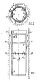
- the well cementing tool shown in Fig. 1 and 2 consists of a substantially tubular cementing collar 1 provided at the upper and lower end thereof with a female and male tool joint 2, 3, respectively, for coupling the collar 1 to adjacent sections of a casing string (not shown).
- the collar 1 has a longitudinal axis I and is provided with a series of port openings 5 which enable a cement slurry which is pumped down through the casing string, as indicated by arrow III, to escape into an annular space 6 formed between the outer surface of the collar and a borehole wall 7 and then to migrate in upward direction through said annular space 6, as indicated by arrows IV.
- Cementing collars of this type are usually indicated as multiple stage cementing collars and they can be mounted at several levels in a well casing to cement the casing inside a borehole along a selected distance, which distance usually spans either the spacing between two cementing collars or the interval between the uppermost collar and the casing top.
- each collar is usually provided at the inside thereof with an opening sleeve and a closing sleeve (not shown) which sleeves can be moved axially in downward direction alongside the inner wall of the collar 1 by means of pump down plugs (not shown) so as to open and close the port openings at will. Since multistage cementing procedures are known per se to those skilled in the art no detailed description thereof is required.
- the port openings consist of bores drilled in radial direction through the tubular wall of the collar. This causes the cement slurry injected through the collar to splash at high speed against the borehole wall and to subsequently migrate in upward direction through the annular space surrounding the casing string.
- the cement slurry after injection thereof into the annular space may be forced to follow a spiralling flow path through the annular space by means of blades which are mounted on the outside of the casing string and are inclined relative to the longitudinal axis thereof.
- the port openings 5 are drilled at such an inclined orientation through the tubular wall of the collar 1 that the cement slurry, immediately upon injection through the port openings 5 follows a swirling flow path through the annular space 6. Thereto the orientation of the port openings 5 is selected such that the central axis V of each port opening 5 crosses the longitudinal axis I of the collar 1 at a selected distance.
- Said mathematical cone has a top angle A which is preferably selected between 60° and 120°.
- the port openings 5 moreover have each a similar orientation relative to the longitudinal axis I of the collar 1, which orientation is selected such that the central axis V of each opening 5 crosses the longitudinal axis at a predetermined angle which is between 0° and 90°.
- Said predetermined angle is preferably selected between 30° and 60°.
- the purpose of the inclined arrangement of the port openings 5 in accordance to the invention is to create a vortex in the flow through the annular space 6 of cement slurry and/or of a cleaning or drilling liquid pushed ahead of the slug of cement slurry during cementation. Due to said vortex high liquid velocities are obtained in said annular space so that the mud cake, gelled drilling mud or other contaminations are flushed away from the borehole wall and outer surface of the casing and a good bonding of the cement to said wall and surface is obtained.
- Creating a vortex by means of the inclined port openings according to the invention eliminates the necessity of the use of spiralling ribs on the outer surface of the casing at least in the region close to the port openings.
- Such spiralling ribs have a tendency to cause at least some flow restriction in the annular space 6.
- Elimination of flow restriction in said annular space has the advantage that with a certain pump pressure of the cement injection pumps a higher cement circulation velocity can be obtained which is beneficial for an uniform rising of the cement slurry through the annular space and for optimized cleaning of the annular space.
Landscapes
- Engineering & Computer Science (AREA)
- Geology (AREA)
- Life Sciences & Earth Sciences (AREA)
- Mining & Mineral Resources (AREA)
- Environmental & Geological Engineering (AREA)
- Fluid Mechanics (AREA)
- Physics & Mathematics (AREA)
- General Life Sciences & Earth Sciences (AREA)
- Geochemistry & Mineralogy (AREA)
- Mechanical Engineering (AREA)
- Display Devices Of Pinball Game Machines (AREA)
- Massaging Devices (AREA)
- Preparation Of Clay, And Manufacture Of Mixtures Containing Clay Or Cement (AREA)
- Structures Of Non-Positive Displacement Pumps (AREA)
Applications Claiming Priority (2)
| Application Number | Priority Date | Filing Date | Title |
|---|---|---|---|
| GB868614632A GB8614632D0 (en) | 1986-06-16 | 1986-06-16 | Well cementing tool |
| GB8614632 | 1986-06-16 |
Publications (2)
| Publication Number | Publication Date |
|---|---|
| EP0250016A2 true EP0250016A2 (de) | 1987-12-23 |
| EP0250016A3 EP0250016A3 (de) | 1989-03-08 |
Family
ID=10599527
Family Applications (1)
| Application Number | Title | Priority Date | Filing Date |
|---|---|---|---|
| EP87200924A Withdrawn EP0250016A3 (de) | 1986-06-16 | 1987-05-18 | Bohrlochzementierungswerkzeug |
Country Status (3)
| Country | Link |
|---|---|
| EP (1) | EP0250016A3 (de) |
| GB (1) | GB8614632D0 (de) |
| NO (1) | NO872465L (de) |
Family Cites Families (4)
| Publication number | Priority date | Publication date | Assignee | Title |
|---|---|---|---|---|
| US1715767A (en) * | 1927-12-17 | 1929-06-04 | Flore Joseph Le | Casing-shoe nozzle |
| US2257765A (en) * | 1939-09-30 | 1941-10-07 | Oil Equipment Engineering Corp | Cementing device for well casings |
| US2703145A (en) * | 1953-05-29 | 1955-03-01 | Standard Oil Dev Co | Well cementing device with jet recycling |
| US3593786A (en) * | 1969-09-10 | 1971-07-20 | Farral F Lewis | Jet wall cleaner |
-
1986
- 1986-06-16 GB GB868614632A patent/GB8614632D0/en active Pending
-
1987
- 1987-05-18 EP EP87200924A patent/EP0250016A3/de not_active Withdrawn
- 1987-06-12 NO NO872465A patent/NO872465L/no unknown
Also Published As
| Publication number | Publication date |
|---|---|
| EP0250016A3 (de) | 1989-03-08 |
| NO872465D0 (no) | 1987-06-12 |
| GB8614632D0 (en) | 1986-07-23 |
| NO872465L (no) | 1987-12-17 |
Similar Documents
| Publication | Publication Date | Title |
|---|---|---|
| US4595058A (en) | Turbulence cementing sub | |
| US2546978A (en) | Well liner and method of cementing | |
| US4844182A (en) | Method for improving drill cuttings transport from a wellbore | |
| US2659438A (en) | Means for cementing wells | |
| US4907649A (en) | Restriction subs for setting cement plugs in wells | |
| MXPA05001748A (es) | Separador de gas-liquido que puede colocarse en el fondo de una perforacion. | |
| EP0250016A2 (de) | Bohrlochzementierungswerkzeug | |
| RU2167273C1 (ru) | Способ установки хвостовика обсадной колонны в скважине | |
| US6311774B1 (en) | Method and apparatus for securing a well casing to a wellbore | |
| US4187911A (en) | Slant hole foam cleanout | |
| CN117888826B (zh) | 钻具及井下定向钻孔压裂套管全程下入方法 | |
| US4842066A (en) | Method for isolation of intake beds in drill holes and a device for carrying same into effect | |
| US2703145A (en) | Well cementing device with jet recycling | |
| SU623954A1 (ru) | Устройство дл создани обратной циркул ции в скважине | |
| CA1154380A (en) | Casing stand-off band for use with running cementing of casing in wellbores | |
| RU2105860C1 (ru) | Наддолотный центратор | |
| WO1987002409A1 (en) | Turbulence cementing sub | |
| US6167917B1 (en) | Drill pipe | |
| US4919208A (en) | Method and apparatus for manipulating tubing in a well | |
| SU1105593A1 (ru) | Бурова установка дл вращательного бурени с обратной промывкой | |
| SU973782A1 (ru) | Калибратор | |
| SU1218079A2 (ru) | Устройство дл разглинизации и кольматации стенок скважины | |
| US4750558A (en) | Well bore cleaning tool | |
| RU2792480C1 (ru) | Устройство для бурения на обсадной колонне | |
| SU73487A1 (ru) | Отклонитель дл бурени горизонтальных скважин |
Legal Events
| Date | Code | Title | Description |
|---|---|---|---|
| PUAI | Public reference made under article 153(3) epc to a published international application that has entered the european phase |
Free format text: ORIGINAL CODE: 0009012 |
|
| AK | Designated contracting states |
Kind code of ref document: A2 Designated state(s): DE FR GB NL |
|
| PUAL | Search report despatched |
Free format text: ORIGINAL CODE: 0009013 |
|
| AK | Designated contracting states |
Kind code of ref document: A3 Designated state(s): DE FR GB NL |
|
| 17P | Request for examination filed |
Effective date: 19890725 |
|
| STAA | Information on the status of an ep patent application or granted ep patent |
Free format text: STATUS: THE APPLICATION IS DEEMED TO BE WITHDRAWN |
|
| 18D | Application deemed to be withdrawn |
Effective date: 19891229 |
|
| RIN1 | Information on inventor provided before grant (corrected) |
Inventor name: VAN BEELEN, COENRADUS GERARDUS |