EP0250004B1 - Rotobaler - Google Patents
Rotobaler Download PDFInfo
- Publication number
- EP0250004B1 EP0250004B1 EP19870110586 EP87110586A EP0250004B1 EP 0250004 B1 EP0250004 B1 EP 0250004B1 EP 19870110586 EP19870110586 EP 19870110586 EP 87110586 A EP87110586 A EP 87110586A EP 0250004 B1 EP0250004 B1 EP 0250004B1
- Authority
- EP
- European Patent Office
- Prior art keywords
- press
- scraper
- roller
- roll
- belts
- Prior art date
- Legal status (The legal status is an assumption and is not a legal conclusion. Google has not performed a legal analysis and makes no representation as to the accuracy of the status listed.)
- Expired - Lifetime
Links
- 238000005096 rolling process Methods 0.000 claims 1
- 230000037452 priming Effects 0.000 description 23
- 238000004804 winding Methods 0.000 description 7
- 230000015572 biosynthetic process Effects 0.000 description 6
- 230000005540 biological transmission Effects 0.000 description 3
- 241000209082 Lolium Species 0.000 description 2
- 230000006835 compression Effects 0.000 description 2
- 238000007906 compression Methods 0.000 description 2
- 230000008878 coupling Effects 0.000 description 1
- 238000010168 coupling process Methods 0.000 description 1
- 238000005859 coupling reaction Methods 0.000 description 1
- 238000012423 maintenance Methods 0.000 description 1
- 230000035515 penetration Effects 0.000 description 1
- 239000010902 straw Substances 0.000 description 1
- 230000001960 triggered effect Effects 0.000 description 1
Images

Classifications
-
- A—HUMAN NECESSITIES
- A01—AGRICULTURE; FORESTRY; ANIMAL HUSBANDRY; HUNTING; TRAPPING; FISHING
- A01F—PROCESSING OF HARVESTED PRODUCE; HAY OR STRAW PRESSES; DEVICES FOR STORING AGRICULTURAL OR HORTICULTURAL PRODUCE
- A01F15/00—Baling presses for straw, hay or the like
- A01F15/07—Rotobalers, i.e. machines for forming cylindrical bales by winding and pressing
- A01F2015/078—Pressing chamber formed exclusively by flexible elements, e.g. belts
-
- A—HUMAN NECESSITIES
- A01—AGRICULTURE; FORESTRY; ANIMAL HUSBANDRY; HUNTING; TRAPPING; FISHING
- A01F—PROCESSING OF HARVESTED PRODUCE; HAY OR STRAW PRESSES; DEVICES FOR STORING AGRICULTURAL OR HORTICULTURAL PRODUCE
- A01F15/00—Baling presses for straw, hay or the like
- A01F15/07—Rotobalers, i.e. machines for forming cylindrical bales by winding and pressing
- A01F2015/0795—Pressing chamber with variable volume
Definitions
- the present invention relates to cylindrical or round balers comprising sets of bands or belts providing a chamber for forming a bale by winding, as well as a collector intended to take the harvested products from the ground for their transfer to the bale forming chamber through a gap or inlet for the products, a non-circular cross-section priming roller being arranged on the other side of this orifice relative to the pick-up to which a member is adjacent.
- Such presses known for example from GB-A-2 010 654 form by winding inside their chamber formed in the body of the press, a generally cylindrical bale from harvested products, in particular fodder or hay, picked up on the spot during the press progress.
- a generally cylindrical bale from harvested products, in particular fodder or hay, picked up on the spot during the press progress.
- the bale has reached the desired diameter and has been tied, the rear door of the press is opened and the bale is unloaded on the ground.
- the formation of another bale by winding can then be triggered inside the press.
- the products intended to form the ball are collected from the ground by means of a collector. They are transferred by the latter into the press chamber, between the strands of the bands or belts, which occupy at the start of the operation neighboring positions. Due to this approximation and the opposite directions of movement of these strands of the bands or belts, the products picked up at the start of the formation of a bale tend to roll up and form the core of a new bale, the diameter of which will increase, the strands of bands or belts moving away from each other according to this increase in diameter of the ball. These bands or belts are then kept under tension by tension rollers which are themselves subjected to the action of springs or hydraulic cylinders.
- a roller As a known manner, towards the front part of the interval or orifice for penetration of the products into the press chamber, a roller called a priming roller, close to a fixed press roller on which the belts or belts pass and which generally serves as a drive roller, see EP-A-076 502.
- the object of the invention is to remedy this drawback of existing presses with a priming roller and, to do this, provision is made for the member adjacent to the priming roller to be a doctor blade placed below said roller and mounted on the press frame pivotally in the vicinity of the priming roller towards which it is resiliently biased.
- This doctor blade is advantageously a lever with two arms of which one arm extends in the vicinity of the priming roller while the other arm, oriented opposite this roller with respect to the pivoting mounting point, is connected to a drive device which subjects the doctor blade to a pivoting movement in synchronism with the rotation of the priming rollers.
- the means ensuring this pivoting of the doctor blade may consist, for example, of a crank, cam or eccentric system.
- the doctor blade extends continuously over the entire width of the press or is formed by separate elements or by teeth close to each other.
- FIG. 1 is a schematic profile representation of a cylindrical baler with priming roller, comprising a doctor blade and fingers associated with this roller, according to main application EP-A-0150 630.
- Figure 2 is a partial view on a larger scale showing a possible embodiment of the invention.
- the reference 1 designates a cylindrical baler of the general conventional type, comprising a fixed front chassis indicated diagrammatically at 2 and supported by wheels 3, this chassis itself carrying a drawbar 4 intended for its coupling to a tractor for example.
- a rear door indicated generally at 5 On the fixed front part 2 forming a frame is articulated in the usual manner a rear door indicated generally at 5, which can pivot on the front part around an upper horizontal transverse axis (not shown), the opening and the closure of this prote being controlled in a conventional manner by hydraulic cylinders or equivalent means (also not shown).
- a set of belts 6 is provided on the press.
- This game includes, in the usual way, a certain number of parallel belts distributed over the width of the press and passing over idler rollers 7-17.
- Some of these deflection rollers are mounted on the fixed front part 2 of the chassis, while others are supported by the rear door 5.
- the strips or belts 6 completely delimit the winding, and a single set of belts is accordingly provided.
- the invention is also applicable in the case of a cylindrical baler comprising a set of belts on the front part of the press and a second set of belts on its rear part or door.
- Some of the deflection rollers are conventionally supported at the end of arms which are themselves pivotally mounted and which are subjected in the usual manner to the action of springs or hydraulic cylinders, in order to ensure the maintenance in tension of the press belts.
- the deflection roller 7 is a drive roller for belts or belts. It is itself driven by a transmission by belts or chains 21 from a return box 22 itself attacked by the transmission shaft 23 connected to the PTO shaft of the tractor. One could also provide a transmission between the roller 7 and another deflection roller, for example the upper roller, to distribute the drive of the bands or belts over two rollers.
- the collector which is mounted in the vicinity of the rear lower roller 11 and which is used to collect from the ground the harvested products which generally lie there in swaths, with a view to their introduction the press chamber through an interval or inlet for the products indicated at 25.
- a priming roller 26 On the other side of this interval 25 relative to the pick-up 24, there is provided in a known manner a priming roller 26.
- the strands of belts which delimit the winding chamber of the press are very close to each other.
- the products picked up by the picker 24 penetrate between these strands of belts through the gap 25. They tend to wind on themselves and this winding is favored by the presence of the priming roller 26, which is driven so positive by means not shown from the drive roller 7.
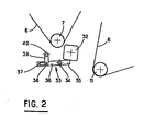
- FIG. 2 which is a view in partial representation, there has been indicated at 7 the return roller for the strips or belts 6, and at 32 the priming roller, here in square cross section.
- This section could also be different, for example hexagonal, or have any other desired profile.
- This priming roller is associated with a doctor blade 33.
- this doctor blade is, in this case, constituted by a lever with two arms 33 which is pivotally mounted on the front part 2 of the press frame at 34.
- the front end 35 of the doctor blade is in the immediate vicinity of the periphery of the priming roller 32 and the rear part 36 of the doctor blade has a slot 37 which is attacked by a finger 38 mounted on a crank arm 39 rotating around an axis 40.
- Its drive is a positive training. It is provided by means not shown, the movement being taken from the deflection or drive roller 7 for example.
- the doctor blade provided according to the invention may extend continuously over the entire width of the press or else it may be formed by separate elements or by teeth brought together.
- a control crank on each side of the press.
- the invention thus remedies the drawbacks mentioned and makes it possible to obtain correct priming in the formation of a ball inside the press chamber, whatever the conditions of the harvested harvested products.
Landscapes
- Life Sciences & Earth Sciences (AREA)
- Environmental Sciences (AREA)
- Harvester Elements (AREA)
- Apparatuses For Bulk Treatment Of Fruits And Vegetables And Apparatuses For Preparing Feeds (AREA)
Claims (4)
Priority Applications (2)
| Application Number | Priority Date | Filing Date | Title |
|---|---|---|---|
| DE8787110586T DE3484020D1 (de) | 1984-01-27 | 1984-01-27 | Rotobaler. |
| EP19870110586 EP0250004B1 (de) | 1984-01-27 | 1984-01-27 | Rotobaler |
Applications Claiming Priority (2)
| Application Number | Priority Date | Filing Date | Title |
|---|---|---|---|
| EP84400188A EP0150630B1 (de) | 1984-01-27 | 1984-01-27 | Rundballenpresse |
| EP19870110586 EP0250004B1 (de) | 1984-01-27 | 1984-01-27 | Rotobaler |
Related Parent Applications (2)
| Application Number | Title | Priority Date | Filing Date |
|---|---|---|---|
| EP84400188A Division EP0150630B1 (de) | 1984-01-27 | 1984-01-27 | Rundballenpresse |
| EP84400188A Division-Into EP0150630B1 (de) | 1984-01-27 | 1984-01-27 | Rundballenpresse |
Publications (3)
| Publication Number | Publication Date |
|---|---|
| EP0250004A2 EP0250004A2 (de) | 1987-12-23 |
| EP0250004A3 EP0250004A3 (en) | 1988-06-08 |
| EP0250004B1 true EP0250004B1 (de) | 1991-01-23 |
Family
ID=26094749
Family Applications (1)
| Application Number | Title | Priority Date | Filing Date |
|---|---|---|---|
| EP19870110586 Expired - Lifetime EP0250004B1 (de) | 1984-01-27 | 1984-01-27 | Rotobaler |
Country Status (1)
| Country | Link |
|---|---|
| EP (1) | EP0250004B1 (de) |
Family Cites Families (4)
| Publication number | Priority date | Publication date | Assignee | Title |
|---|---|---|---|---|
| DE7430874U (de) * | 1974-09-13 | 1977-05-26 | Welger Geb | Aufsammel-rollballenpresse |
| US4155298A (en) * | 1977-03-21 | 1979-05-22 | Hesston Corporation | Bale starting gate for rotary baler |
| US4182101A (en) * | 1977-12-01 | 1980-01-08 | Hesston Corporation | Machine for coiling fibrous crop materials into large round bales |
| FR2546368B1 (fr) * | 1983-05-27 | 1986-03-28 | Hesston Sa | Dispositif de relevage pour des machines destinees au ramassage et au pressage en balles rondes de tous types de recolte |
-
1984
- 1984-01-27 EP EP19870110586 patent/EP0250004B1/de not_active Expired - Lifetime
Also Published As
| Publication number | Publication date |
|---|---|
| EP0250004A2 (de) | 1987-12-23 |
| EP0250004A3 (en) | 1988-06-08 |
Similar Documents
| Publication | Publication Date | Title |
|---|---|---|
| EP0150630B1 (de) | Rundballenpresse | |
| EP0149368B1 (de) | Rundballenpresse | |
| BE1007190A5 (fr) | Machine de recolte pour former des balles rondes. | |
| EP0064117B1 (de) | Ohne Unterbrechung arbeitende Rundballenpresse | |
| FR2549688A1 (fr) | Machine pour ramasser et former en balles rondes des matieres fibreuses disposees en andains | |
| EP0046426B1 (de) | Rundballenpresse | |
| EP0228944B1 (de) | Vorrichtung für die Bildung von Rundballen von Futter in einer Rundballenpresse | |
| EP0064112B1 (de) | Rundballenpresse | |
| EP0150629A1 (de) | Rundballenpresse mit Drehmomentbegrenzer | |
| EP0090120B1 (de) | Bindevorrichtung mittels zwei Bindfäden für Rundballenpresse | |
| FR2511838A1 (fr) | Machine rotative de mise en balles de recoltes | |
| EP0150631B1 (de) | Rundballenpresse mit Antrieb der Anlaufrolle | |
| EP0130258A1 (de) | Rollballenpresse | |
| EP0250004B1 (de) | Rotobaler | |
| EP0064116B1 (de) | Ohne Unterbrechung arbeitende Rundballenpresse | |
| EP0041444B1 (de) | Bindevorrichtung für Rundballenpresse | |
| FR2604856A1 (fr) | Presse a grosses balles pour produits de recoltes agricoles | |
| EP0298798A2 (de) | Vorrichtung zur Verkleinerung der Breite der Schwade eines landwirtschaftlichen Sammlers | |
| FR2604857A1 (fr) | Procede et dispositif de commande de bras de guidage de ficelle de liage de balles cylindriques dans une presse ramasseuse | |
| EP0150628B1 (de) | Rundballenpresse mit Anordnung, um die Spannung in den Bändern zu erhöhen | |
| FR2575362A1 (fr) | Machine destinee a former des balles cylindriques | |
| US5408925A (en) | Trash removal apparatus for a round baler | |
| EP3612016B1 (de) | Schwadbelüftervorrichtung und mit solch einer vorrichtung ausgestattete landwirtschaftliche maschine | |
| EP0131078B1 (de) | Rollballenpresse mit Mähwerk | |
| EP0137882B1 (de) | Bindevorrichtung für Rundballenpresse |
Legal Events
| Date | Code | Title | Description |
|---|---|---|---|
| PUAI | Public reference made under article 153(3) epc to a published international application that has entered the european phase |
Free format text: ORIGINAL CODE: 0009012 |
|
| AC | Divisional application: reference to earlier application |
Ref document number: 150630 Country of ref document: EP |
|
| AK | Designated contracting states |
Kind code of ref document: A2 Designated state(s): DE FR GB IT NL |
|
| PUAL | Search report despatched |
Free format text: ORIGINAL CODE: 0009013 |
|
| AK | Designated contracting states |
Kind code of ref document: A3 Designated state(s): DE FR GB IT NL |
|
| 17P | Request for examination filed |
Effective date: 19880702 |
|
| 17Q | First examination report despatched |
Effective date: 19891025 |
|
| ITF | It: translation for a ep patent filed | ||
| GRAA | (expected) grant |
Free format text: ORIGINAL CODE: 0009210 |
|
| AC | Divisional application: reference to earlier application |
Ref document number: 150630 Country of ref document: EP |
|
| AK | Designated contracting states |
Kind code of ref document: B1 Designated state(s): DE FR GB IT NL |
|
| PGFP | Annual fee paid to national office [announced via postgrant information from national office to epo] |
Ref country code: NL Payment date: 19910131 Year of fee payment: 8 |
|
| GBT | Gb: translation of ep patent filed (gb section 77(6)(a)/1977) | ||
| REF | Corresponds to: |
Ref document number: 3484020 Country of ref document: DE Date of ref document: 19910228 |
|
| PGFP | Annual fee paid to national office [announced via postgrant information from national office to epo] |
Ref country code: DE Payment date: 19910319 Year of fee payment: 8 |
|
| PLBE | No opposition filed within time limit |
Free format text: ORIGINAL CODE: 0009261 |
|
| STAA | Information on the status of an ep patent application or granted ep patent |
Free format text: STATUS: NO OPPOSITION FILED WITHIN TIME LIMIT |
|
| PGFP | Annual fee paid to national office [announced via postgrant information from national office to epo] |
Ref country code: GB Payment date: 19911211 Year of fee payment: 9 |
|
| 26N | No opposition filed | ||
| PGFP | Annual fee paid to national office [announced via postgrant information from national office to epo] |
Ref country code: FR Payment date: 19920117 Year of fee payment: 9 |
|
| PG25 | Lapsed in a contracting state [announced via postgrant information from national office to epo] |
Ref country code: NL Effective date: 19920801 |
|
| NLV4 | Nl: lapsed or anulled due to non-payment of the annual fee | ||
| PG25 | Lapsed in a contracting state [announced via postgrant information from national office to epo] |
Ref country code: DE Effective date: 19921001 |
|
| PG25 | Lapsed in a contracting state [announced via postgrant information from national office to epo] |
Ref country code: GB Effective date: 19930127 |
|
| GBPC | Gb: european patent ceased through non-payment of renewal fee |
Effective date: 19930127 |
|
| PG25 | Lapsed in a contracting state [announced via postgrant information from national office to epo] |
Ref country code: FR Effective date: 19930930 |
|
| REG | Reference to a national code |
Ref country code: FR Ref legal event code: ST |