EP0249981A2 - Verstellbare Montagevorrichtung für einen Behälter - Google Patents
Verstellbare Montagevorrichtung für einen Behälter Download PDFInfo
- Publication number
- EP0249981A2 EP0249981A2 EP87108794A EP87108794A EP0249981A2 EP 0249981 A2 EP0249981 A2 EP 0249981A2 EP 87108794 A EP87108794 A EP 87108794A EP 87108794 A EP87108794 A EP 87108794A EP 0249981 A2 EP0249981 A2 EP 0249981A2
- Authority
- EP
- European Patent Office
- Prior art keywords
- assembly
- circuit board
- movement
- end cap
- respect
- Prior art date
- Legal status (The legal status is an assumption and is not a legal conclusion. Google has not performed a legal analysis and makes no representation as to the accuracy of the status listed.)
- Withdrawn
Links
Images

Classifications
-
- H—ELECTRICITY
- H05—ELECTRIC TECHNIQUES NOT OTHERWISE PROVIDED FOR
- H05K—PRINTED CIRCUITS; CASINGS OR CONSTRUCTIONAL DETAILS OF ELECTRIC APPARATUS; MANUFACTURE OF ASSEMBLAGES OF ELECTRICAL COMPONENTS
- H05K13/00—Apparatus or processes specially adapted for manufacturing or adjusting assemblages of electric components
- H05K13/0061—Tools for holding the circuit boards during processing; handling transport of printed circuit boards
- H05K13/0069—Holders for printed circuit boards
Definitions
- This invention relates to a holder assembly for printed circuit boards such as those used in conjunction with tote boxes for automatic handling. More particularly, the invention relates to an adjustable circuit board holder assembly which is used as a divider in a tote box and can be infinitely adjusted to facilitate the robotic selection and handling of printed circuit boards.
- Holding members for printed circuit boards in the form of clamping devices are known such as indicated in U.S. Patent 3,767,058. Circuit board retainers are also described in U.S. 3,845,359 wherein compression screws are utilized in conjunction with springs for holding the circuit board.
- U.S. Patent 4,184,599 a storage device for holding a plurality of printed circuit boards between two movable type protions is provided.
- An adjustable circuit card retainer is described in U.S. Patent 4,462,499 wherein a card retaining bracket is placed in slidable communication with a mounting bracket so that it is adjustable with respect to the card.
- the prior art does not provide a circuit board holder which can effect incremental adjustment of a printed circuit board for robotic handling.
- the prior art is either concerned with devices for connecting or storing printed circuit boards in box-like containers.
- an adjustable circuit board holding device is afforded for the robotic handling of the printed circuit boards, it does not provide for incremental adjustment of the printed circuit board.
- the present invention therefore provides an adjustable mounting device which includes a first member adapted for placement in contact with a wall surface of a container. Means are operatively associated with the first member and the wall surface to restrict movement of the first member in a first direction. A second member is adapted for connection with a holding member for articles to be placed in the container. Means are operatively associated with the first and second members to effect the movement of the second member with respect to the first member when the first member is restricted in movement in the first direction. Finally guide means are operatively associated with the first and second members to effect the movement of the second member in the first direction.
- circuit board holder of the invention allows for a simple and quick adjustment of divider devices to fit various size circuit boards in a snug manner.
- circuit board holders are of a uniform dimension so that inventory costs are reduced and usage is simplified.
- circuit board holders of the invention can be manufactured at low cost from readily available materials and can be easily assembled.
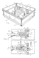
- the circuit board holder assembly includes two of the mounting devices shown at 10 in Fig. 1 positioned in a tote box generally 11.
- the tote box 11 in this instance has the usual front wall 12, a back wall 13, side walls 14 and 15 as well as a bottom wall 20. It also has a bumper rim 16.
- This particular tote box is the subject matter of U.S. Patent 4,499,997.
- circuit board holder face 17 is positioned against the side wall 15 and another similar but longer circuit board holder face 18 is positioned against the back wall 13. They are also secured to the inside of front wall 12 as well as side wall 14 such as by means of sonic welding. In each instance, the circuit board holder faces 17 and 18 will have an upper rail portion such as shown at 30.
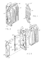
- Each of the holder assemblies 10 include a divider plate 24 which receives the opposing circuit board holder faces 25 and 75 on each side thereof. This divider plate will secure the circuit board holder faces 25 and 75 in a manner to be later described in conjunction with Fig. 6.
- the circuit board holder faces 25 and 75 have the slots 26 and 76 therein for receiving the printed circuit boards such as 22 and 23.
- the holder assemblies 10 include an end cap body 27 having the flanges 28 and 29 which are receivable in the slots 32 and 33 of the divider plate member 24. These slots 32 and 33 are formed from a spacing between the circuit board holder faces 25, 75 and a central panel section 31 (See Figs. 4 and 5).
- the divider plate 24 will be retained in the slotted wave form 19 of front and back wall circuit board holder faces 18 by the end cap slide 34 having the flange 35 retained in the slots 21. This is best seen in conjunction with Fig. 2.
- the end cap slide 34 is slidably retained in a frame 36 composing a part of the end cap body 27 which also has the support wall 37.
- Projections 38, 39, 40 and 41 extend outwardly from the support wall 37 and have the engagement surfaces such as 57 for slidable engagement along the guide ways 52, 53, 54 and 55 of the end cap slide 34.
- the support wall 37 has a longitudinally extending slot 69 for receiving the drive shaft 45 as well as a compartment 42 with a support wall 43 for accommodating the screw threads 47 of the shaft 45.
- a slotted head portion 46 extends from shaft 45 which has the intermediary screw threads 47.
- a slotted portion 49 Connected to shaft 45 is a slotted portion 49 with two protrusions 50 and 51 extending outwardly and transversely with respect to the slot 49. These serve as part of a detent mechanism as will be further explained in conjunction with the description of Figs. 8 and 9.
- the end cap body also has a recess 44 at the top as well as an associated wall portion 62 for receiving and providing support to the circular flange 71 of the drive shaft 45.
- end cap slide 34 has a rib 67 extending diagonally over the back thereof. This serves as part of the detent mechanism which is described in conjunction with Figs. 8 and 9.
- circuit board faces 25 and 75 are held in the divider plate 24 having the opposing T-shaped heads 58 and 59.
- Flanges 60, 60a and 72, 72a are spaced from the central panel 31 to afford slots or tracks 73, 73a, 73b and 73c so as to receive the inset flanges 61, 61a, 61b and 61c of the circuit board holder faces 25 and 75.
- end cap slide 34 includes a threaded rack 64 extending from the rear thereof and opposite the flange 35.
- the threaded rack 64 engages the screw threads 47 on the drive shaft 45 as positioned in the compartment 42.
- the threads 47 will be held captive in the compartment 42 by the wall surfaces 43 and 73.
- the flange 71 is accommodated in the recess 44 and rests on the wall 62.
- the drive shaft 45 rests on the support wall 77, which is an extension of a back wall portion 70 of the end cap body 27.
- An extending foot portion 48 provides a standoff which serves to stablilize the holder assembly 10 in the tote box 11 and a heel portion 63 provides a support for head 59 so as to space the holder assembly 10 above the bottom wall 20. This compensates for any warping of the bottom wall.
- a detent mechanism is afforded for the drive shaft 45.
- This is accomplished by a U-shaped compartment 89 formed by a U-shaped wall portion 70 extending from the back of support wall 37 and the protrusions 50 and 51 extending from the drive shaft 45.
- These protrusions 50 and 51 engage the projections 66 extending from wall portion 70 as well as rib 67 extending from the back of end cap slide 34.
- This detent mechanism aids in avoiding undesired turning of the shaft 45 such as during shipping.
- projections 50 and 51 are in the position shown in Fig. 9, shaft 45 cannot be rotated without a force being applied.
- projections 50 and 51 engage projection 66 and rib 67 with a compression of slot 49. This effects sufficient resistance until the projections 50 and 51 are again diagonally positioned.
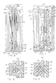
- FIG. 10 and 11 An alternative embodiment of the holder assembly is shown in Figs. 10 and 11 designated generally 80.
- the end cap slide 81 is similar to end cap slide 34 except that on the reverse side it has two parallel ribs 85 and 86 for capturing the nut 83 in the slot 84 when the nut 83 and the bolt 82 are posi tioned in the slot 69 with nut 83 slidably received therein.
- end cap body 87 is similar thereto and has the recess 44 and the wall 62 for supporting the head 88 of the bolt 82.
- embodiment 80 is similar to the previously described embodiment 10 in that end cap slide 81 has the flange 35 for retention in the slots 21 of the wave form 19.
- Flanges 78 and 79 extend from the back of the end cap body 87 for receiving a divider plate 24 in the same manner as described for flanges 28 and 29 of the end cap body 27.
- an additional embodiment 90 is depicted.
- This embodiment differs from the previous one in that instead of a threaded engagement means for moving end cap body 97 laterally relative to the end cap slide 91 there is a ratchet mechanism represented by the arm 92 extending from the end cap slide 91 having the grooves 93.
- This arm 92 is biased in a manner to enage the wall 95 provided in the opening 94 in the end cap body 97 which also is of a rectangular frame structure 36.
- the support wall 96 of end cap body 97 does not have a slot but does have the same projections 38-41 for engaging the slides such as 52, 53 and 55 and their undercuts 56. It also has the flanges 98 and 99 for receiving the divider plate 24.
- the holder assembly 10 will be better understood by description of its fabrication and operation.
- the assembly of the holder assembly generally 10 is best indicated in conjunction with Fig. 5.
- the unit is composed of four parts: the end cap slide 34, the drive shaft 45, the end cap body 27 and the divider plate 24.
- the drive shaft 45 will be aligned and inserted through the slot 69 with the shaft 45 seated in the end cap body 27 as shown in Fig. 7. This will be initially effected by positioning the shaft 45 at a steep angle with respect to end cap body 27 so the slotted head 46 can be inserted through opening 63 leading into the recess 44.
- the next step is to slidably position the undercuts 56 on the guide ways 52-55 of the end cap slide 34 so as to press fit them together with the engagement surfaces 57 of the projections 38-41. In this position, the threads 47 of the projections 38-41. In this position, the threads 47 of the drive shaft 45 engage the threaded rack 64 of the end cap slide 34. Also in this position the end cap body 27 is ready to engage the divider plate 24 or holder member. This is effected by positioning the flanges 28 and 29 into the slots 32 and 33 of the divider plate 24.
- Next is to place two of the holder assemblies 10 into the box 11 and between the circuit board holder faces 18 which are positioned on the inside of the walls 12 and 13. This is effected by placing the extending flanges 35 into the adjacent slotted wave form 19.
- the widths of circuit boards such as 22 and 23 will vary from each other so that the adjustment to receive their end edge sections in the slots such as 26 and 76 is critical. To adjust for these variations in widths, all that is required is a turning of the drive shaft 45. This would ordinarily cause the end cap 34 to move in an angular manner with respect to the end cap body 27 through the engagement of the screw threads 47 and threaded rack 64. However, the following factors must be considered. The flange 35 is now held in the circuit board holder face 18 and in the wave form 19 so that lateral movement is prevented. Also, the factor that the guide ways 52-54 as well as the projections 38-41 are positioned at an oblique angle with respect to the flange.
- embodiments 80 and 90 The operation of embodiments 80 and 90 is substantially the same as previously described for embodiment 10.
- the same lateral motion of the end cap bodies 87 and 97 will be effected when the flanges 35 are restrained from lateral movement in the slots 21 of the wave form 19.
- the turning of the bolt 82 with the capture of the nut 83 in the end cap slide 81 will effect the lateral movement of the end cap body 87 and the divider plates 24.
- a movement of the rachet arm 92 inwardly or outwardly with respect to the end cap body 97 will effect the same lateral motion of the end cap body 97 and the divider plates 24.
- the preferred materials for injection molding of the end cap slides 34, 81 and 91, the drive shaft 45, the bolt 82 and the nut 83 as well as the end cap bodies 27, 87 and 97 is an acetal plastic.
- other plastic materials such as nylon or A.B.S. can be employed.
- the circuit board holder faces 25 and 75 are molded from a polypropylene material whereas the divider plate 24 is extruded aluminum.
- Other lightweight plastic and metal materials could be substituted.
- a slotted head 46 is provided on the shaft 45. This affords engagement with a screw driver. If desired, a slotted tab could be substituted for finger engagement with a portion of the tabs being removed to provide a slot for a screwdriver.
- the detent mechanism is employed in conjunction with the protrusions 50, 51 and the slot 49. While this feature is advantageous in preventing the screw threads 47 from turning during transportation, this feature could be eliminated and still obtain the advantages of the device for this invention.
- a compartment 42 is provided for the threads 47 and allows for expansion therein should the end cap slide be forced against a restraining surface such as the bottom wall 20 of the tote box 11 or a surface of the end cap body. This also could be eliminated.
- An oblique angle of approximately 30° is preferred for the slide guide ways 52-55. Any angle which will afford a lateral movement of the end cap body 27 could be utilized.
- holder device 10 has been shown in conjunction with a facing board 25 on each side of the holder 24. This is not essential and the advantages of this invention could be accomplished with only a single facing board being employed on one side. Also, while two holder devices have been illustrated, some of the advantages of this invention could be accomplished by using a non-adjustable divider holder panel in combination with an adjustable one.
- a holder assembly for circuit boards which is infinitely adjustable and thus lends itself to robotic handling.
- the holder assemblies provide for fast and efficient placement in the container as well as versatility in accommodating various types of facing board holders.
- the holder assemblies of this invention are adaptable to being utilized as adjustable divider plates allowing for simple, quick adjustment of the dividers to accommodate various widths of circuit boards snugly with a single divider plate.
- the holder assemblies are of uniform constructions thus reducing inventorying of different assemblies.
Landscapes
- Engineering & Computer Science (AREA)
- Manufacturing & Machinery (AREA)
- Microelectronics & Electronic Packaging (AREA)
- Packaging Frangible Articles (AREA)
- Automatic Assembly (AREA)
- Transmission Devices (AREA)
Applications Claiming Priority (2)
| Application Number | Priority Date | Filing Date | Title |
|---|---|---|---|
| US876775 | 1986-06-20 | ||
| US06/876,775 US4746015A (en) | 1986-06-20 | 1986-06-20 | Adjustable circuit board holder assembly |
Publications (2)
| Publication Number | Publication Date |
|---|---|
| EP0249981A2 true EP0249981A2 (de) | 1987-12-23 |
| EP0249981A3 EP0249981A3 (de) | 1990-01-17 |
Family
ID=25368553
Family Applications (1)
| Application Number | Title | Priority Date | Filing Date |
|---|---|---|---|
| EP87108794A Withdrawn EP0249981A3 (de) | 1986-06-20 | 1987-06-19 | Verstellbare Montagevorrichtung für einen Behälter |
Country Status (5)
| Country | Link |
|---|---|
| US (1) | US4746015A (de) |
| EP (1) | EP0249981A3 (de) |
| CA (1) | CA1275639C (de) |
| DE (1) | DE249981T1 (de) |
| FI (1) | FI872702A7 (de) |
Cited By (1)
| Publication number | Priority date | Publication date | Assignee | Title |
|---|---|---|---|---|
| GB2326871A (en) * | 1997-07-04 | 1999-01-06 | Peter Sweeny | Carriers for transport of electronic circuits |
Families Citing this family (14)
| Publication number | Priority date | Publication date | Assignee | Title |
|---|---|---|---|---|
| US5103998A (en) * | 1990-06-06 | 1992-04-14 | Dolly Caro | Multi-compartment recycling container |
| US5139430A (en) * | 1990-06-28 | 1992-08-18 | Digital Equipment Corporation | PCB insertion/ejection lever mechanism |
| DE69232154T2 (de) * | 1991-12-16 | 2002-03-07 | Venturedyne, Ltd. | Verbesserte halterung zum testen von leiterplatten |
| USD361753S (en) | 1993-09-29 | 1995-08-29 | Lasroc Ltd. | Carrier for printed circuits |
| USD361318S (en) | 1993-09-29 | 1995-08-15 | Lasroc Ltd. | Carrier for printed circuits |
| JP2788901B2 (ja) * | 1996-07-03 | 1998-08-20 | 日本電気エンジニアリング株式会社 | 基板用カセット |
| US6030060A (en) * | 1998-07-22 | 2000-02-29 | Drake; Leo O. | Adjustable circuit card storage device |
| US6681480B1 (en) * | 1999-02-26 | 2004-01-27 | Micron Technology, Inc. | Method and apparatus for installing a circuit device |
| US6328169B1 (en) * | 2000-06-12 | 2001-12-11 | Nikko Kogyo Kabushiki Kaisha | Frame structure for housing panel plates |
| US6606248B2 (en) * | 2002-01-04 | 2003-08-12 | Micron Technology, Inc. | Universal memory module/PCB storage, transport, automation handling tray |
| US20040007486A1 (en) * | 2002-05-24 | 2004-01-15 | Bergh James A. | Adjustable partition device for portable containers |
| US7654408B2 (en) * | 2005-09-06 | 2010-02-02 | Bradford Company | Container with locking strips |
| US20070136966A1 (en) * | 2005-12-15 | 2007-06-21 | 3M Innovative Properties Company | Lint remover |
| JP5715021B2 (ja) * | 2011-09-30 | 2015-05-07 | 三洋電機株式会社 | 梱包容器 |
Family Cites Families (6)
| Publication number | Priority date | Publication date | Assignee | Title |
|---|---|---|---|---|
| GB1392713A (en) * | 1971-03-26 | 1975-04-30 | Smiths Industries Ltd | Mounting arrangements |
| US3845359A (en) * | 1973-10-17 | 1974-10-29 | D Fedele | Circuit board anchor having constrained deformable strut |
| US4184599A (en) * | 1977-11-17 | 1980-01-22 | Drake Leo O | Printed circuit board storage device |
| US4261465A (en) * | 1979-08-29 | 1981-04-14 | C. R. Daniels, Inc. | Tote box for carrying different length circuit boards |
| US4462499A (en) * | 1982-08-16 | 1984-07-31 | Calabro Anthony Denis | Adjustable circuit card retainer |
| US4527222A (en) * | 1983-02-24 | 1985-07-02 | Menasha Corporation | Precision tote box insert for holding and locating printed circuit boards or the like |
-
1986
- 1986-06-20 US US06/876,775 patent/US4746015A/en not_active Expired - Fee Related
-
1987
- 1987-06-17 FI FI872702A patent/FI872702A7/fi not_active IP Right Cessation
- 1987-06-18 CA CA000540038A patent/CA1275639C/en not_active Expired - Fee Related
- 1987-06-19 EP EP87108794A patent/EP0249981A3/de not_active Withdrawn
- 1987-06-19 DE DE198787108794T patent/DE249981T1/de active Pending
Cited By (1)
| Publication number | Priority date | Publication date | Assignee | Title |
|---|---|---|---|---|
| GB2326871A (en) * | 1997-07-04 | 1999-01-06 | Peter Sweeny | Carriers for transport of electronic circuits |
Also Published As
| Publication number | Publication date |
|---|---|
| DE249981T1 (de) | 1988-06-09 |
| CA1275639C (en) | 1990-10-30 |
| US4746015A (en) | 1988-05-24 |
| EP0249981A3 (de) | 1990-01-17 |
| FI872702A7 (fi) | 1987-12-21 |
| FI872702A0 (fi) | 1987-06-17 |
Similar Documents
| Publication | Publication Date | Title |
|---|---|---|
| EP0249981A2 (de) | Verstellbare Montagevorrichtung für einen Behälter | |
| US4527222A (en) | Precision tote box insert for holding and locating printed circuit boards or the like | |
| US4627760A (en) | Plate holder | |
| US5555302A (en) | Mobile telephone holder | |
| US4232356A (en) | Logic card frame | |
| CA1057238A (en) | Support for dispensing packages | |
| US4768660A (en) | Adjustable hook and mounting rail assembly | |
| US12319499B2 (en) | Goods taking mechanism and carrying device | |
| US5230554A (en) | Sliding storage basket | |
| US4763782A (en) | Circuit board holder | |
| US6328169B1 (en) | Frame structure for housing panel plates | |
| CA2080262A1 (en) | Multi-stage storage case for cassettes or cassette blocks | |
| US4260208A (en) | Manufacturing fixture and support for magnetic disc | |
| GB2110076A (en) | A mounting device | |
| US6239978B1 (en) | Circuit board support | |
| US5380079A (en) | Storing device having upper and lower rod separators | |
| US5542635A (en) | File container assembly including brackets for wall or cart mounting | |
| JP3677071B2 (ja) | スライドプレートの取付構造 | |
| GB2041726A (en) | Storage cabinets | |
| JPH0420263Y2 (de) | ||
| JP2003136143A (ja) | ベンダー金型の収納ラック | |
| JP3655518B2 (ja) | オプション部材の取付構造 | |
| KR200269291Y1 (ko) | 인쇄회로기판 보관용 매거진 | |
| CN218410438U (zh) | 搁架组件和储物装置 | |
| JP3146869B2 (ja) | 自動販売機のスパイラル式商品収納ラック |
Legal Events
| Date | Code | Title | Description |
|---|---|---|---|
| PUAI | Public reference made under article 153(3) epc to a published international application that has entered the european phase |
Free format text: ORIGINAL CODE: 0009012 |
|
| AK | Designated contracting states |
Kind code of ref document: A2 Designated state(s): DE FR GB IT SE |
|
| EL | Fr: translation of claims filed | ||
| DET | De: translation of patent claims | ||
| PUAL | Search report despatched |
Free format text: ORIGINAL CODE: 0009013 |
|
| AK | Designated contracting states |
Kind code of ref document: A3 Designated state(s): DE FR GB IT SE |
|
| 17P | Request for examination filed |
Effective date: 19900716 |
|
| STAA | Information on the status of an ep patent application or granted ep patent |
Free format text: STATUS: THE APPLICATION HAS BEEN WITHDRAWN |
|
| 18W | Application withdrawn |
Withdrawal date: 19910828 |
|
| RIN1 | Information on inventor provided before grant (corrected) |
Inventor name: KAUCIC, EDWARD M. |