EP0249936A2 - Method for molding powders - Google Patents
Method for molding powders Download PDFInfo
- Publication number
- EP0249936A2 EP0249936A2 EP87108630A EP87108630A EP0249936A2 EP 0249936 A2 EP0249936 A2 EP 0249936A2 EP 87108630 A EP87108630 A EP 87108630A EP 87108630 A EP87108630 A EP 87108630A EP 0249936 A2 EP0249936 A2 EP 0249936A2
- Authority
- EP
- European Patent Office
- Prior art keywords
- mold
- thin
- wall
- ventilative
- wall resilient
- Prior art date
- Legal status (The legal status is an assumption and is not a legal conclusion. Google has not performed a legal analysis and makes no representation as to the accuracy of the status listed.)
- Withdrawn
Links
Images

Classifications
-
- B—PERFORMING OPERATIONS; TRANSPORTING
- B22—CASTING; POWDER METALLURGY
- B22F—WORKING METALLIC POWDER; MANUFACTURE OF ARTICLES FROM METALLIC POWDER; MAKING METALLIC POWDER; APPARATUS OR DEVICES SPECIALLY ADAPTED FOR METALLIC POWDER
- B22F3/00—Manufacture of workpieces or articles from metallic powder characterised by the manner of compacting or sintering; Apparatus specially adapted therefor ; Presses and furnaces
- B22F3/12—Both compacting and sintering
- B22F3/1208—Containers or coating used therefor
- B22F3/1216—Container composition
- B22F3/1233—Organic material
-
- B—PERFORMING OPERATIONS; TRANSPORTING
- B22—CASTING; POWDER METALLURGY
- B22F—WORKING METALLIC POWDER; MANUFACTURE OF ARTICLES FROM METALLIC POWDER; MAKING METALLIC POWDER; APPARATUS OR DEVICES SPECIALLY ADAPTED FOR METALLIC POWDER
- B22F3/00—Manufacture of workpieces or articles from metallic powder characterised by the manner of compacting or sintering; Apparatus specially adapted therefor ; Presses and furnaces
- B22F3/02—Compacting only
- B22F3/04—Compacting only by applying fluid pressure, e.g. by cold isostatic pressing [CIP]
-
- B—PERFORMING OPERATIONS; TRANSPORTING
- B30—PRESSES
- B30B—PRESSES IN GENERAL
- B30B11/00—Presses specially adapted for forming shaped articles from material in particulate or plastic state, e.g. briquetting presses, tabletting presses
- B30B11/001—Presses specially adapted for forming shaped articles from material in particulate or plastic state, e.g. briquetting presses, tabletting presses using a flexible element, e.g. diaphragm, urged by fluid pressure; Isostatic presses
-
- Y—GENERAL TAGGING OF NEW TECHNOLOGICAL DEVELOPMENTS; GENERAL TAGGING OF CROSS-SECTIONAL TECHNOLOGIES SPANNING OVER SEVERAL SECTIONS OF THE IPC; TECHNICAL SUBJECTS COVERED BY FORMER USPC CROSS-REFERENCE ART COLLECTIONS [XRACs] AND DIGESTS
- Y10—TECHNICAL SUBJECTS COVERED BY FORMER USPC
- Y10S—TECHNICAL SUBJECTS COVERED BY FORMER USPC CROSS-REFERENCE ART COLLECTIONS [XRACs] AND DIGESTS
- Y10S264/00—Plastic and nonmetallic article shaping or treating: processes
- Y10S264/78—Processes of molding using vacuum
-
- Y—GENERAL TAGGING OF NEW TECHNOLOGICAL DEVELOPMENTS; GENERAL TAGGING OF CROSS-SECTIONAL TECHNOLOGIES SPANNING OVER SEVERAL SECTIONS OF THE IPC; TECHNICAL SUBJECTS COVERED BY FORMER USPC CROSS-REFERENCE ART COLLECTIONS [XRACs] AND DIGESTS
- Y10—TECHNICAL SUBJECTS COVERED BY FORMER USPC
- Y10S—TECHNICAL SUBJECTS COVERED BY FORMER USPC CROSS-REFERENCE ART COLLECTIONS [XRACs] AND DIGESTS
- Y10S425/00—Plastic article or earthenware shaping or treating: apparatus
- Y10S425/014—Expansible and collapsible
Definitions
- the present invention relates to a method for molding powders, and more particularly to a method for cold isostatic press.
- a cold isostatic press (hereinafter abbribiated to C.I.P.) method is well known as a method wherein metallic or ceramic powders are charged into a resilient mold, the mold being sealed, and applied pressure to at the normal temperature, to produce a homogeneous green compact.
- C.I.P. cold isostatic press
- the resilient mold is, during the process of C.I.P., so hard to deform, and, the cover and the corners of the resilient mold are, in particular, so hard to deform that the dimensional accuracy of the shape-forming becomes low. Consequently, this method is disadvantageous in that considerable machining on the green compact is required for shape modification after the C.I.P. process is finished.
- the simple thin resilient pouch or sack is used. Since the shape of the pouch or sack is different from that of the ventilative mold for outer supporting, the expansion of the thin resilient pouch is different, in places, when the pouch is put close to the ventilative mold by making use of the balance between the outside pressure of the mold and the inside pressure of the pouch. The contract of the pouch is differently produced, when the C.I.P. treatment is applied. Resultantly, the edge parts of a green compact, particularly required to be accurate in dimension, is forced to become round. The accuracy in dimension remains still unsolved in this method.
- a method for molding powders which comprises the steps of: introducing a thin-wall resilient mold similar to an inside shape of a ventilative mold support and to a shape of a green compact, into the inside of the ventilative mold support; reducing pressure outside the ventilative mold support, by operation of vacuum pump, to less than the atmospheric pressure (760 Torr), to put the thin resilient mold close to the inside wall of the ventilative mold support: supplying material powders into the thin-wall resilient mold; exhausting air existing in the voids which the material powders form; and sealing the thin-resilient mold; and taking out the thin-wall resilient mold filled with the material powders by taking the ventilative mold support apart to apply C.I.P. treatment to the thin-wall resilient mold.
- Figs. 1 to 6 are schematic views illustrating sequentially and specifically respective steps according to the present invention.
- FIG. 1 to 6 schematically illustrate respective steps in sequence according to the present invention.
- vacuum vessel 1 is composed of upper cover 3 equipped with gate 2, cylinder 4 and lifting table 5.
- Ventilative mold support 7 is installed, on sample support 6, mounted on the lifting table.
- Ventilative mold support 7 is equipped with opening 8 on its top. Opening 8 and gate 2 have a concentric center. The top surface of ventilative mold 7 and upper cover 3 are put close together.
- the opening of thin-wall resilient mold 9 is fixed to gate 2 and the thin- wall resilient mold is introduced into the inside of ventilative mold support 7.
- the thin-wall resilient mold 9 is similar to an inside shape of the ventilative mold support i.e., to a shape of a green compact.
- the pressure outside the ventilative mold support is reduced to less than the atmospheric pressure (760 Torr), by means of vacuum pump 12, through a leading pipe set in the ventilative mold support, the leading pipe being provided with dust filter 11, so as for thin-wall resilient mold 9 to be put completely close to the whole inside shape of ventilative mold support 7.
- the thin-wall resilient mold be put exactly close to the inside wall of the ventilative mold support as if the shape of the thin-wall resilient mold were equal to that of the ventilative mold support.
- the pressure outside the ventilative mold support is set preferably to 400 Torr or less. If the pressure outside is over 400 Torr, the thin-wall resilient mold fails to be close enough to be put to the inside wall of the ventilative mold. If the pressure outside is reduced to approximately 10 Torr, almost any kind of thin-wall resilient rubber molds 9 can be put close to the ventilative mold.
- material powders 13 is supplied through feeder 14 into the thin-wall resilient mold.
- a vibrator can be used, and, alternatively, the end level of feeder 14 is vertically moved depending on the condition of the fill-up.
- the pressure inside thin-wall resilient mold 9 is set preferably to 100 Torr or less, and more preferably to 10 Torr or less. If the pressure inside is over 100 Torr, the balance between the pressure inside and the atmospheric pressure becomes too small to keep the shape of pre-mold body 21, which will be described later. If the pressure inside is 10 Torr or less, the shape is strengthen harder. It is also preferable to keep pump 12 in operation during the exhaust of the air existing in the voids, in order that the pressure outside ventilative mold support 7 may be maintained lower than the pressure inside thin-wall resilient mold 9.
- pre-molded body 21 As shown in Fig. 5, subsequently vacuum vessel 1 is taken away, and, further, ventilative mold support 7 is taken apart, to take out pre-mold body 21. Since the inside of the pre-molded body is less than the atmospheric pressure (760 Torr), the pre-molded body is always receiving the isostatic pressure corresponding to the balance between the pressure outside the ventilative mold support 7 and the pressure inside thin-wall resilient mold 9. Resultantly, the pre-molded body, i.e., the shape of the thin-wall resilient mold can continue, without the ventilative mold support, to be the shape as it is.
- pre-molded body 21 is housed in C.I.P apparatus 22.
- Water is introduced into the C.I.P apparatus to increase pressure therein and to keep the increased pressure for several minutes. This allows the pre-molded body to contract and increase in desity to turn into green compact 23.
- the pressure is desired to be increased to 2000 to 4000 atm., when ceramic powders are used as material powders. Even if the pressure is increased to more than 4000 atm., the fill-up density is unchangeable since ceramic powders do not deform plastically. Contrary, if the the pressure is 2000 atm. or less, the fill-up density is not satisfactory. When metallic powders are used as material powders, 2000 to 6000 atm. of the pressure is preferable. Even if the pressure is increased over 6000 atm., the effect in increasing the fill-up density is considered to be small, although metallic powders deform plastically. If the pressure is less than 2000 atm., the fill-up density is not satisfactory.
- a green compact, thus molded, can be easily taken out by means of taking clamp 20 off and removing thin-wall resilient mold 9.
- Material for ventilative mold support 7 can be any one selected from the group consisting of plastics, metal, ceramics, and composite material of ceramics and metal.
- plastics polyamide resin, polycarbonate resin, ABS resin or AS resin can be used.
- metal copper alloy, stainless steel or alminium can be used.
- ceramics almina and silica can be used. Ventilation performance of the ventilative mold support can be improved by giving vent-holes to the aforementioned materials.
- the ventilative mold support can be made of porous materials. The porous materials are made by mixing porous materials or use of foaming agents. As the porous materials, gymsum or molding sand can be used.
- the thin-wall resilient mold is a mold, rich in elasticity, formed of natural or synthetic rubber.
- synthetic rubber stylene-butadiene rubber, polyisoprane rubber or isobutylane-isoprane rubber is preferable.
- the thin-wall resilient mold has a shape similar to an inside shape of the ventilative mold support, and a feature of being put exactly close to the inside wall of the ventilative mold support, without expansion.
- the thin-wall resilient mold can be a mold having a feature of being put exactly close to the inside shape of ventilative mold support when the mold is slightly expanded by an equal proportion on the whole shape.
- the thickness of the thin-wall resilient mold ranges 50 to 2000 ⁇ m preferably, although depending on the size and shape of the mold. The range of 100 to 500 ⁇ m is more preferable. If the thickness is less than 50 ⁇ m, it happens to cause pin holes on the mold or to break the mold. If it is 2000 ⁇ m or less, the mold is kept exactly close to pre-molded body 21. On the other hand, if it is over 2000 ⁇ m, the pre-molded body is sometimes broken, owing to the restration work of the mold.
- the thin-wall resilient mold is manufactured by a method wherein the metallic pattern is first prepared, and dipped in latex to which a coagulant has been added, and then, the dipped metallic pattern taken out, are heated to accelerate hardening of the latex on the surface of the metallic pattern.
- the heating temperature ranges from 50 to 90°C preferably.
- the heating is carried out by putting the metallic mold covered by the latex into a heating furnace or by blowing hot air on the metallic pattern. In stead of the heating, the latex on the surface of the metallic pattern can be hardend by being released in the air.
- Materials for a green compact are recommended to be processed so as to have a good fluidity and packing characteristics in particle size and shape.
- spherical powders by means of argon atomizing method, vacuum spraying method or rotating electrode method.
- titanium or titanium alloy it is desirable to use spherical powders by plasma rotating electrode method.
- carbonyl iron metallic powders of carbonyl-nickel, dispersion-strengthened metallic powders of super alloy, alumina, zirconia, silicon nitride, silicon carbide or sialon, it is preferable to granulate powders into spherical form.
- An alminium pattern was firstly prepared.
- the pattern was equipped with a shaft of 20 mm in diameter and 60 mm in length, and with a disk plate of 80 mm in diameter and 20 mm in thickness attached to the shaft at a distance of 20 mm of one end of the shaft.
- the pattern was dipped in latex to which a coagulant had been added.
- the dipped pattern was taken out and heated at the temperature of 70°C, to form a thin-wall latex mold of approximately 100 ⁇ m in thickness, similar to the shape of the pattern.
- a porous mold support of gympsum having a cavity similar to the shape of the pattern was also prepared.
- the thin-wall latex mold was put close to the porous gympsum mold support, thereby to form a pre- molded body.
- C.I.P treatment was applied at pressure of 5000kg/cm2, and to the almina powders at pressure of 3,000kg/cm2.
- the roundness of the molded disk plate was measured. In either of the cases of the measurement, the dispersion of the disk diameter was 0.1% or less.
- a green compact having a gear shape was manufactured by using a atomized stainless steel powders as material powders.
- a thin-wall latex mold was prepared by using the alminium pattern in the same manner as mentioned in Example 1. Subsequently, an urethane resin mold support having the same cavity with the shape of the thin-wall latex mold, by using the alminium pattern.
- the thin-wall latex mold was put close to the inside wall of the urethane resin mold support by means of suction through vent-holes provided for the urethane resin mold support.
- the molding was carried out, and, subsequently, C,I.P. treatment was applied at pressure of 5000 kg/cm2.
- the green compact had dispersion nearly to zero, and, the gear teeth of the green compact were finely accurate in demension and shape, covering the accuracy of the top edge of the teeth.
- a green compact with valve shape was produced by using spherical almina granular powders of 50 to 100 ⁇ m in particle size as material powders.
- an alminium pattern having a shaft of 20 mm in diameter and 100 mm in length and a disk plate of 80 mm in diameter and 20 mm in thickness in the shaft end, was prepared.
- the pattern was dipped in latex to which a coagulant had been added.
- the dipped pattern was taken out and heated to form a thin-wall latex mold of approximately 100 ⁇ m in thickness.
- a wooden mold support provided with vent-holes was also prepared by using the same pattern.
- the pre-molding was carried out by putting the thin-wall latex mold close to the wooden mold support.
- the C.I.P. treatment was applied at pressure of 3000kg/cm2.
- a pre-molded body contracted isostatically.
- a green compact with high accuracy in demension and shape was obtained.
- a product by a conventional method employing a thin resilient pouch there was found no creases in the part connecting the disk plate with the shaft where the dimension is drastically changed.
- the method for molding powders according to the present invention enabled to mold a green compact with a complicated shape and with high accuracy in dimension, and particularly with end edge sharpness in shape which had been considered unobtainable.
Landscapes
- Engineering & Computer Science (AREA)
- Mechanical Engineering (AREA)
- Physics & Mathematics (AREA)
- Fluid Mechanics (AREA)
- Manufacturing & Machinery (AREA)
- Press-Shaping Or Shaping Using Conveyers (AREA)
- Devices For Post-Treatments, Processing, Supply, Discharge, And Other Processes (AREA)
- Powder Metallurgy (AREA)
- Moulds For Moulding Plastics Or The Like (AREA)
Abstract
Description
- The present invention relates to a method for molding powders, and more particularly to a method for cold isostatic press.
- A cold isostatic press (hereinafter abbribiated to C.I.P.) method is well known as a method wherein metallic or ceramic powders are charged into a resilient mold, the mold being sealed, and applied pressure to at the normal temperature, to produce a homogeneous green compact. In order to obtain a compact of a desired shape, however, it is required to use a resilient mold which has thickness and strength enough not to deform due to the weight of the powders. In this case, the resilient mold is, during the process of C.I.P., so hard to deform, and, the cover and the corners of the resilient mold are, in particular, so hard to deform that the dimensional accuracy of the shape-forming becomes low. Consequently, this method is disadvantageous in that considerable machining on the green compact is required for shape modification after the C.I.P. process is finished.
- To overcome these difficulties, various methods have been reported. For examples, Japanese Patent Applications, Examined Publication No. 56499/85 and Laid open No. 183780/84 disclose a method wherein:
- (a) a ventilative mold of porous material is used for outer-supporting;
- (b) a thin resilient cover is installed along the inside wall of the ventilative mold, the outside pressure of the ventilative mold being reduced;
- (c) Powder materials for the molding are charged into the thin resilient pouch and followed by the process wherein the outside pressure of the resilient mold is increased and, in addition, the inside pressure of the thin resilient pouch is reduced; and
- (d) The ventilative mold for outer supporting is removed, and, then, the thin resilient pouch is applied C.I.P. to.
- In this method, however, the simple thin resilient pouch or sack is used. Since the shape of the pouch or sack is different from that of the ventilative mold for outer supporting, the expansion of the thin resilient pouch is different, in places, when the pouch is put close to the ventilative mold by making use of the balance between the outside pressure of the mold and the inside pressure of the pouch. The contract of the pouch is differently produced, when the C.I.P. treatment is applied. Resultantly, the edge parts of a green compact, particularly required to be accurate in dimension, is forced to become round. The accuracy in dimension remains still unsolved in this method.
- It is an object of the present invention to provide a method for molding powders in accuracy in dimension.
- In accordance with the present invention, a method is provided for molding powders which comprises the steps of:
introducing a thin-wall resilient mold similar to an inside shape of a ventilative mold support and to a shape of a green compact, into the inside of the ventilative mold support;
reducing pressure outside the ventilative mold support, by operation of vacuum pump, to less than the atmospheric pressure (760 Torr), to put the thin resilient mold close to the inside wall of the ventilative mold support:
supplying material powders into the thin-wall resilient mold;
exhausting air existing in the voids which the material powders form; and
sealing the thin-resilient mold; and
taking out the thin-wall resilient mold filled with the material powders by taking the ventilative mold support apart to apply C.I.P. treatment to the thin-wall resilient mold. - Other objects and advantages of the present invention will become more apparent from the detailed description to follow taken in conjunction with the appended drawings.
- Figs. 1 to 6 are schematic views illustrating sequentially and specifically respective steps according to the present invention.
- Referring now specifically to the drawings, an embodiment of the present invention will be described in detail. Figs. 1 to 6 schematically illustrate respective steps in sequence according to the present invention.
- Turning to Fig. 1, vacuum vessel 1 is composed of
upper cover 3 equipped withgate 2,cylinder 4 and lifting table 5.Ventilative mold support 7 is installed, onsample support 6, mounted on the lifting table.Ventilative mold support 7 is equipped with opening 8 on its top. Opening 8 andgate 2 have a concentric center. The top surface ofventilative mold 7 andupper cover 3 are put close together. With reference specifically to Fig. 2, the opening of thin-wallresilient mold 9 is fixed togate 2 and the thin- wall resilient mold is introduced into the inside ofventilative mold support 7. The thin-wallresilient mold 9 is similar to an inside shape of the ventilative mold support i.e., to a shape of a green compact. The pressure outside the ventilative mold support is reduced to less than the atmospheric pressure (760 Torr), by means ofvacuum pump 12, through a leading pipe set in the ventilative mold support, the leading pipe being provided withdust filter 11, so as for thin-wallresilient mold 9 to be put completely close to the whole inside shape ofventilative mold support 7. In this process, it is required that the thin-wall resilient mold be put exactly close to the inside wall of the ventilative mold support as if the shape of the thin-wall resilient mold were equal to that of the ventilative mold support. - The pressure outside the ventilative mold support is set preferably to 400 Torr or less. If the pressure outside is over 400 Torr, the thin-wall resilient mold fails to be close enough to be put to the inside wall of the ventilative mold. If the pressure outside is reduced to approximately 10 Torr, almost any kind of thin-wall
resilient rubber molds 9 can be put close to the ventilative mold. - As shown in Fig. 3, when the shape of the resilient thin-wall mold is completely formed,
material powders 13 is supplied through feeder 14 into the thin-wall resilient mold. In order to fill up the material powders homogeneously and in high packing density with the thin-wall resilient mold, a vibrator can be used, and, alternatively, the end level of feeder 14 is vertically moved depending on the condition of the fill-up. - With reference to Fig. 4, when the fill-up of
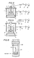
material powders 13 is finished,empty room 19 is formed above the top level of the material powders withingate 2, whereindust filter 15 is set, to exhaust air existing in the voids, which the material powders form, by means ofvacuum pump 18 connected withdust filter 15 through a leading pipe provided withvalve 16 anddust filter 17 on the way. The pressure inside thin-wallresilient mold 9 is set preferably to 100 Torr or less, and more preferably to 10 Torr or less. If the pressure inside is over 100 Torr, the balance between the pressure inside and the atmospheric pressure becomes too small to keep the shape ofpre-mold body 21, which will be described later. If the pressure inside is 10 Torr or less, the shape is strengthen harder. It is also preferable to keeppump 12 in operation during the exhaust of the air existing in the voids, in order that the pressure outsideventilative mold support 7 may be maintained lower than the pressure inside thin-wallresilient mold 9. - With particular reference to Fig. 5, when the pressure inside the thin-wall resilient mold reaches a predetermined pressure, the exhausting operation of
pump 12 is stopped and the pressure outsideventilative mold support 7 is brought, through change of air-flow by means of three-waychangeable cock 10, to the atmosphric pressure. At this stage, the part of the shape of the thin-wall resilient mold surrounded byempty room 19 is collapsed and the collapsed part of the mold is nippled byclamp 20 to be sealed. - As shown in Fig. 5, subsequently vacuum vessel 1 is taken away, and, further,
ventilative mold support 7 is taken apart, to take out pre-moldbody 21. Since the inside of the pre-molded body is less than the atmospheric pressure (760 Torr), the pre-molded body is always receiving the isostatic pressure corresponding to the balance between the pressure outside theventilative mold support 7 and the pressure inside thin-wallresilient mold 9. Resultantly, the pre-molded body, i.e., the shape of the thin-wall resilient mold can continue, without the ventilative mold support, to be the shape as it is. - Lastly, as shown in Fig. 6 of the drawing, pre-molded
body 21 is housed inC.I.P apparatus 22. Water is introduced into the C.I.P apparatus to increase pressure therein and to keep the increased pressure for several minutes. This allows the pre-molded body to contract and increase in desity to turn intogreen compact 23. The pressure is desired to be increased to 2000 to 4000 atm., when ceramic powders are used as material powders. Even if the pressure is increased to more than 4000 atm., the fill-up density is unchangeable since ceramic powders do not deform plastically. Contrary, if the the pressure is 2000 atm. or less, the fill-up density is not satisfactory. When metallic powders are used as material powders, 2000 to 6000 atm. of the pressure is preferable. Even if the pressure is increased over 6000 atm., the effect in increasing the fill-up density is considered to be small, although metallic powders deform plastically. If the pressure is less than 2000 atm., the fill-up density is not satisfactory. - A green compact, thus molded, can be easily taken out by means of taking
clamp 20 off and removing thin-wallresilient mold 9. - Material for
ventilative mold support 7 can be any one selected from the group consisting of plastics, metal, ceramics, and composite material of ceramics and metal. As the plastics, polyamide resin, polycarbonate resin, ABS resin or AS resin can be used. As the metal, copper alloy, stainless steel or alminium can be used. As the ceramics, almina and silica can be used. Ventilation performance of the ventilative mold support can be improved by giving vent-holes to the aforementioned materials. The ventilative mold support can be made of porous materials. The porous materials are made by mixing porous materials or use of foaming agents. As the porous materials, gymsum or molding sand can be used. - The thin-wall resilient mold is a mold, rich in elasticity, formed of natural or synthetic rubber. As the synthetic rubber, stylene-butadiene rubber, polyisoprane rubber or isobutylane-isoprane rubber is preferable. It is preferable that the thin-wall resilient mold has a shape similar to an inside shape of the ventilative mold support, and a feature of being put exactly close to the inside wall of the ventilative mold support, without expansion. Alternatively, the thin-wall resilient mold can be a mold having a feature of being put exactly close to the inside shape of ventilative mold support when the mold is slightly expanded by an equal proportion on the whole shape.
- The thickness of the thin-wall resilient mold ranges 50 to 2000 µm preferably, although depending on the size and shape of the mold. The range of 100 to 500 µm is more preferable. If the thickness is less than 50 µm, it happens to cause pin holes on the mold or to break the mold. If it is 2000 µm or less, the mold is kept exactly close to
pre-molded body 21. On the other hand, if it is over 2000 µm, the pre-molded body is sometimes broken, owing to the restration work of the mold. - The thin-wall resilient mold is manufactured by a method wherein the metallic pattern is first prepared, and dipped in latex to which a coagulant has been added, and then, the dipped metallic pattern taken out, are heated to accelerate hardening of the latex on the surface of the metallic pattern. The heating temperature ranges from 50 to 90°C preferably. The heating is carried out by putting the metallic mold covered by the latex into a heating furnace or by blowing hot air on the metallic pattern. In stead of the heating, the latex on the surface of the metallic pattern can be hardend by being released in the air.
- Materials for a green compact are recommended to be processed so as to have a good fluidity and packing characteristics in particle size and shape. Specifically, for example, when stainless steel, tool steel or superalloy is manufactured, it is appropriate to use spherical powders by means of argon atomizing method, vacuum spraying method or rotating electrode method. In the case of titanium or titanium alloy, it is desirable to use spherical powders by plasma rotating electrode method. In the case of carbonyl iron, metallic powders of carbonyl-nickel, dispersion-strengthened metallic powders of super alloy, alumina, zirconia, silicon nitride, silicon carbide or sialon, it is preferable to granulate powders into spherical form.
- Two kinds of samples for green compacts were prepared; steel spherical powders in particle size of 80 to 200 meshes and almina powders in particle size of 20 to 100 µm.
- An alminium pattern was firstly prepared. The pattern was equipped with a shaft of 20 mm in diameter and 60 mm in length, and with a disk plate of 80 mm in diameter and 20 mm in thickness attached to the shaft at a distance of 20 mm of one end of the shaft.
Subsequently, the pattern was dipped in latex to which a coagulant had been added. Then, the dipped pattern was taken out and heated at the temperature of 70°C, to form a thin-wall latex mold of approximately 100 µm in thickness, similar to the shape of the pattern. A porous mold support of gympsum having a cavity similar to the shape of the pattern was also prepared. - The thin-wall latex mold was put close to the porous gympsum mold support, thereby to form a pre- molded body. To the steel spherical powders, C.I.P treatment was applied at pressure of 5000kg/cm², and to the almina powders at pressure of 3,000kg/cm². The roundness of the molded disk plate was measured. In either of the cases of the measurement, the dispersion of the disk diameter was 0.1% or less. The disk diameters actually measured for each, were given as follows:
For steel spherical powders: 70.83 ± 0.08 mm
For alminum powders : 68.10± 0.05 mm - A green compact having a gear shape was manufactured by using a atomized stainless steel powders as material powders.
- Firstly, prepared was an alminum pattern having a disk plate of 50 mm in diameter and 10 mm in thickness provided with thirty teeth, and having a shaft of 10 mm in diameter and 50 mm in length in the center of the disk plate.
- A thin-wall latex mold was prepared by using the alminium pattern in the same manner as mentioned in Example 1. Subsequently, an urethane resin mold support having the same cavity with the shape of the thin-wall latex mold, by using the alminium pattern.
- The thin-wall latex mold was put close to the inside wall of the urethane resin mold support by means of suction through vent-holes provided for the urethane resin mold support. Thus, the molding was carried out, and, subsequently, C,I.P. treatment was applied at pressure of 5000 kg/cm². A green compact increased in density, was obtained. The green compact had dispersion nearly to zero, and, the gear teeth of the green compact were finely accurate in demension and shape, covering the accuracy of the top edge of the teeth.
- A green compact with valve shape was produced by using spherical almina granular powders of 50 to 100 µm in particle size as material powders.
- Firstly, an alminium pattern, having a shaft of 20 mm in diameter and 100 mm in length and a disk plate of 80 mm in diameter and 20 mm in thickness in the shaft end, was prepared. The pattern was dipped in latex to which a coagulant had been added. The dipped pattern was taken out and heated to form a thin-wall latex mold of approximately 100 µm in thickness. Subsequently, a wooden mold support provided with vent-holes was also prepared by using the same pattern.
- The pre-molding was carried out by putting the thin-wall latex mold close to the wooden mold support. The C.I.P. treatment was applied at pressure of 3000kg/cm².
- A pre-molded body contracted isostatically. A green compact with high accuracy in demension and shape was obtained. Especially, in comparison with a product by a conventional method employing a thin resilient pouch, there was found no creases in the part connecting the disk plate with the shaft where the dimension is drastically changed.
- As described in the above, the method for molding powders according to the present invention enabled to mold a green compact with a complicated shape and with high accuracy in dimension, and particularly with end edge sharpness in shape which had been considered unobtainable.
Claims (20)
reducing the pressure outside a ventilative mold support (7), by operation of a vacuum pump (12), to less than the atmospheric pressure (760 Torr), to put a thin-wall resilient mold (9) close to the inside wall of the ventilative mold support;
supplying material powders into the thin-wall resilient mold;
exhausting air existing in the voids which the material powders form;
sealing the thin-wall resilient mold; and
taking out the thin-wall resilient mold filled with the material powders by taking the ventilative mold support, to apply cold isostatistic press treatment to the thin-wall resilient mold;
characterized by comprising introducing the thinwall resilient mold similar to an inside shape of the ventilative mold support and to a shape of a green compact into the inside of the mold support.
dipping a metallic pattern in latex to form a film over the metallic pattern; and
heating the film over the metalic pattern.
dipping a metallic pattern in latex to form a film over the metallic pattern; and releasing the metallic pattern to the air.
Applications Claiming Priority (2)
| Application Number | Priority Date | Filing Date | Title |
|---|---|---|---|
| JP139158/86 | 1986-06-17 | ||
| JP61139158A JPS62297402A (en) | 1986-06-17 | 1986-06-17 | Powder molding method |
Publications (2)
| Publication Number | Publication Date |
|---|---|
| EP0249936A2 true EP0249936A2 (en) | 1987-12-23 |
| EP0249936A3 EP0249936A3 (en) | 1989-11-15 |
Family
ID=15238927
Family Applications (1)
| Application Number | Title | Priority Date | Filing Date |
|---|---|---|---|
| EP87108630A Withdrawn EP0249936A3 (en) | 1986-06-17 | 1987-06-16 | Method for molding powders |
Country Status (3)
| Country | Link |
|---|---|
| US (1) | US4761264A (en) |
| EP (1) | EP0249936A3 (en) |
| JP (1) | JPS62297402A (en) |
Cited By (4)
| Publication number | Priority date | Publication date | Assignee | Title |
|---|---|---|---|---|
| EP0393335A3 (en) * | 1989-04-18 | 1991-01-02 | Nkk Corporation | Method for molding powders |
| EP0403743A3 (en) * | 1989-06-22 | 1991-02-06 | Nkk Corporation | Method for molding powders |
| CN102554226A (en) * | 2012-02-28 | 2012-07-11 | 南通富仕液压机床有限公司 | Powder metallurgy pressing mould base |
| GB2572775A (en) * | 2018-04-10 | 2019-10-16 | Rolls Royce Plc | Methods of Manufacture |
Families Citing this family (10)
| Publication number | Priority date | Publication date | Assignee | Title |
|---|---|---|---|---|
| US5200125A (en) * | 1988-12-24 | 1993-04-06 | T&K International Laboratory, Ltd. | Method for seal molding electronic components with resin |
| US5194268A (en) * | 1990-06-07 | 1993-03-16 | The Dow Chemical Company | Apparatus for injection molding a ceramic greenware composite without knit lines |
| US5098620A (en) * | 1990-06-07 | 1992-03-24 | The Dow Chemical Company | Method of injection molding ceramic greenward composites without knit lines |
| US5244623A (en) * | 1991-05-10 | 1993-09-14 | Ferro Corporation | Method for isostatic pressing of formed powder, porous powder compact, and composite intermediates |
| JPH07266090A (en) * | 1994-03-31 | 1995-10-17 | Ngk Insulators Ltd | Isotropic press forming method for powder molding |
| JP2970569B2 (en) * | 1997-01-13 | 1999-11-02 | 日本電気株式会社 | Resin sealing method and resin sealing mold device |
| US6540852B1 (en) * | 1998-07-21 | 2003-04-01 | Acadia Elastomers Corporation | Apparatus and method for manufacturing gaskets |
| JP4223830B2 (en) * | 2003-02-21 | 2009-02-12 | マツダ株式会社 | Water-soluble casting mold and manufacturing method thereof |
| US7255191B2 (en) * | 2003-10-31 | 2007-08-14 | Vectrix Corporation | Composite construction vehicle frame |
| US7927525B2 (en) * | 2007-08-24 | 2011-04-19 | Lizotte Todd E | Vacuum isostatic micro molding of micro/nano structures and micro transfer metal films into PTFE and PTFE compounds |
Family Cites Families (8)
| Publication number | Priority date | Publication date | Assignee | Title |
|---|---|---|---|---|
| US1883854A (en) * | 1926-02-09 | 1932-10-18 | Dermatoid Werke Paul Meissner | Ornamentation of celluloid |
| US1863854A (en) * | 1929-11-04 | 1932-06-21 | Champion Porcelain Company | Method of and apparatus for shaping articles |
| GB787352A (en) * | 1955-03-17 | 1957-12-04 | Gen Electric Co Ltd | Improvements in or relating to the manufacture of metal articles from metal powders |
| SE323179B (en) * | 1967-11-08 | 1970-04-27 | Asea Ab | |
| US3551946A (en) * | 1968-08-26 | 1971-01-05 | Wah Chang Albany Corp | Method and apparatus for compacting isostatically metal particles into solid form |
| US3862286A (en) * | 1972-10-10 | 1975-01-21 | Aluminum Co Of America | Method of fabricating compacted powdered metal extrusion billets |
| DE3328954C1 (en) * | 1983-08-11 | 1985-01-31 | MTU Motoren- und Turbinen-Union München GmbH, 8000 München | Process for the production of molded parts by cold isostatic pressing |
| JPS6164801A (en) * | 1984-09-04 | 1986-04-03 | Nippon Kokan Kk <Nkk> | Method for forming powders such as metals and ceramics |
-
1986
- 1986-06-17 JP JP61139158A patent/JPS62297402A/en active Pending
-
1987
- 1987-06-12 US US07/061,896 patent/US4761264A/en not_active Expired - Fee Related
- 1987-06-16 EP EP87108630A patent/EP0249936A3/en not_active Withdrawn
Cited By (6)
| Publication number | Priority date | Publication date | Assignee | Title |
|---|---|---|---|---|
| EP0393335A3 (en) * | 1989-04-18 | 1991-01-02 | Nkk Corporation | Method for molding powders |
| US5030401A (en) * | 1989-04-18 | 1991-07-09 | Nkk Corporation | Method for molding powders |
| EP0403743A3 (en) * | 1989-06-22 | 1991-02-06 | Nkk Corporation | Method for molding powders |
| US4999157A (en) * | 1989-06-22 | 1991-03-12 | Nkk Corporation | Method for molding powders |
| CN102554226A (en) * | 2012-02-28 | 2012-07-11 | 南通富仕液压机床有限公司 | Powder metallurgy pressing mould base |
| GB2572775A (en) * | 2018-04-10 | 2019-10-16 | Rolls Royce Plc | Methods of Manufacture |
Also Published As
| Publication number | Publication date |
|---|---|
| JPS62297402A (en) | 1987-12-24 |
| EP0249936A3 (en) | 1989-11-15 |
| US4761264A (en) | 1988-08-02 |
Similar Documents
| Publication | Publication Date | Title |
|---|---|---|
| US4761264A (en) | Method for molding powders | |
| US4927600A (en) | Method for molding of powders | |
| CA1271011A (en) | Method of molding powders of metal, ceramic and the like | |
| ZA200410364B (en) | Method for producing highly porous metallic moulded bodies approximating the desired final contours | |
| EP0572280A1 (en) | Slip casting method for manufacturing ceramic articles | |
| US4999157A (en) | Method for molding powders | |
| US5850590A (en) | Method for making a porous sintered material | |
| US6527038B1 (en) | Tooling production | |
| WO1997040777A2 (en) | Net shaped dies and molds and method for producing the same | |
| JPH02501721A (en) | Heterogeneous porous mold for manufacturing molds from foundry sand and its manufacturing method | |
| US5997603A (en) | Sintered metal mould and method for producing the same | |
| JPH10509665A (en) | Apparatus for directing fluid between a chamber and a channel bounded by a hard surface, and a method of manufacturing the apparatus | |
| JP2004174861A (en) | Mold for bottomed ceramic pipe and method of manufacturing the same | |
| US6203734B1 (en) | Low pressure injection molding of metal and ceramic powders using soft tooling | |
| US5030401A (en) | Method for molding powders | |
| JPS5712607A (en) | Metallic mold for resin | |
| JPS6242805A (en) | Method of molding ceramic pipe body | |
| JPH01304902A (en) | Method and apparatus for forming ceramic | |
| JPS62202003A (en) | Molding method for powder | |
| JPS61152738A (en) | Mold for vacuum forming of plastic | |
| JPS6212196B2 (en) | ||
| Stieler | Contribution to the Mould Material Practice for the Vacuum Moulding Process | |
| JP2000309008A (en) | Manufacturing method of ceramic plate | |
| JPH0999417A (en) | Manufacture of ceramic member and molding method for ceramic powder | |
| JPS63252702A (en) | Molding method for ceramic molded bodies |
Legal Events
| Date | Code | Title | Description |
|---|---|---|---|
| PUAI | Public reference made under article 153(3) epc to a published international application that has entered the european phase |
Free format text: ORIGINAL CODE: 0009012 |
|
| 17P | Request for examination filed |
Effective date: 19870616 |
|
| AK | Designated contracting states |
Kind code of ref document: A2 Designated state(s): DE FR GB SE |
|
| PUAL | Search report despatched |
Free format text: ORIGINAL CODE: 0009013 |
|
| AK | Designated contracting states |
Kind code of ref document: A3 Designated state(s): DE FR GB SE |
|
| 17Q | First examination report despatched |
Effective date: 19910729 |
|
| STAA | Information on the status of an ep patent application or granted ep patent |
Free format text: STATUS: THE APPLICATION IS DEEMED TO BE WITHDRAWN |
|
| 18D | Application deemed to be withdrawn |
Effective date: 19930213 |
|
| RIN1 | Information on inventor provided before grant (corrected) |
Inventor name: HARADA, JUNPAT&LIC, QUALITY STANDARDS DEPT. Inventor name: NISHIO, HIROAKIPAT&LIC, QUALITY STANDARDS DEPT. |