EP0249845A1 - Machine tool - Google Patents
Machine tool Download PDFInfo
- Publication number
- EP0249845A1 EP0249845A1 EP87108251A EP87108251A EP0249845A1 EP 0249845 A1 EP0249845 A1 EP 0249845A1 EP 87108251 A EP87108251 A EP 87108251A EP 87108251 A EP87108251 A EP 87108251A EP 0249845 A1 EP0249845 A1 EP 0249845A1
- Authority
- EP
- European Patent Office
- Prior art keywords
- machine tool
- line
- workpiece table
- headstock
- portal frame
- Prior art date
- Legal status (The legal status is an assumption and is not a legal conclusion. Google has not performed a legal analysis and makes no representation as to the accuracy of the status listed.)
- Granted
Links
Images


Classifications
-
- B—PERFORMING OPERATIONS; TRANSPORTING
- B23—MACHINE TOOLS; METAL-WORKING NOT OTHERWISE PROVIDED FOR
- B23Q—DETAILS, COMPONENTS, OR ACCESSORIES FOR MACHINE TOOLS, e.g. ARRANGEMENTS FOR COPYING OR CONTROLLING; MACHINE TOOLS IN GENERAL CHARACTERISED BY THE CONSTRUCTION OF PARTICULAR DETAILS OR COMPONENTS; COMBINATIONS OR ASSOCIATIONS OF METAL-WORKING MACHINES, NOT DIRECTED TO A PARTICULAR RESULT
- B23Q1/00—Members which are comprised in the general build-up of a form of machine, particularly relatively large fixed members
- B23Q1/0009—Energy-transferring means or control lines for movable machine parts; Control panels or boxes; Control parts
-
- Y—GENERAL TAGGING OF NEW TECHNOLOGICAL DEVELOPMENTS; GENERAL TAGGING OF CROSS-SECTIONAL TECHNOLOGIES SPANNING OVER SEVERAL SECTIONS OF THE IPC; TECHNICAL SUBJECTS COVERED BY FORMER USPC CROSS-REFERENCE ART COLLECTIONS [XRACs] AND DIGESTS
- Y10—TECHNICAL SUBJECTS COVERED BY FORMER USPC
- Y10T—TECHNICAL SUBJECTS COVERED BY FORMER US CLASSIFICATION
- Y10T408/00—Cutting by use of rotating axially moving tool
- Y10T408/52—Cutting by use of rotating axially moving tool with work advancing or guiding means
- Y10T408/54—Means to intermittently advance work
- Y10T408/545—Rotary, work-supporting means
-
- Y—GENERAL TAGGING OF NEW TECHNOLOGICAL DEVELOPMENTS; GENERAL TAGGING OF CROSS-SECTIONAL TECHNOLOGIES SPANNING OVER SEVERAL SECTIONS OF THE IPC; TECHNICAL SUBJECTS COVERED BY FORMER USPC CROSS-REFERENCE ART COLLECTIONS [XRACs] AND DIGESTS
- Y10—TECHNICAL SUBJECTS COVERED BY FORMER USPC
- Y10T—TECHNICAL SUBJECTS COVERED BY FORMER US CLASSIFICATION
- Y10T409/00—Gear cutting, milling, or planing
- Y10T409/30—Milling
- Y10T409/306664—Milling including means to infeed rotary cutter toward work
- Y10T409/307448—Milling including means to infeed rotary cutter toward work with work holder
- Y10T409/307504—Indexable
-
- Y—GENERAL TAGGING OF NEW TECHNOLOGICAL DEVELOPMENTS; GENERAL TAGGING OF CROSS-SECTIONAL TECHNOLOGIES SPANNING OVER SEVERAL SECTIONS OF THE IPC; TECHNICAL SUBJECTS COVERED BY FORMER USPC CROSS-REFERENCE ART COLLECTIONS [XRACs] AND DIGESTS
- Y10—TECHNICAL SUBJECTS COVERED BY FORMER USPC
- Y10T—TECHNICAL SUBJECTS COVERED BY FORMER US CLASSIFICATION
- Y10T409/00—Gear cutting, milling, or planing
- Y10T409/30—Milling
- Y10T409/30868—Work support
- Y10T409/308792—Indexable
- Y10T409/308848—Indexable including dividing head
Definitions
- the invention relates to a machine tool with a headstock which can be moved in several coordinate axes, with a workpiece table which can be rotated in opposite directions about an axis perpendicular to its surface in such a way that an angle of preferably 180 ° can be rotated so that in each case one half of the surface of the workpiece table alternately has a machining side in it Work area of the headstock and forms a component side at a distance from the work area of the headstock, at least one line for signals and / or energy being led from a fixed part of the machine tool to the workpiece table.
- Such a machine tool is known from DE-GM 83 16 776.
- machine tools it is known not only to make the part of the machine carrying the machining tool movable, for example the headstock, it is also known to move the table carrying the workpiece in a linear or a rotary movement. This movement of the table can be used to guide the workpiece along a stationary tool for machining.
- rotary tables are also used in order to be able to already mount the next workpiece on the other side while machining a workpiece on one side of the rotary table, so that, for example, the new workpiece can be machined by rotating the table by 180 ° can be recorded immediately after finishing the machining of the old workpiece.
- this configuration of a turntable also has the advantage that the approach accuracy from the workpiece to the tool is particularly high, because the simple rotary movement can be carried out precisely and easily, for example by 180 °.
- connections to the rotary table can be used to convey energy in the form of compressed air or hydraulic fluid from the machine tool to the rotary table or to exchange signals between the machine tool and the workpiece table. This is typically the case when the workpiece is held on the workpiece table by means of a power-operated clamping device or a dividing device.
- energies are required, e.g. can be supplied in the form of electrical current, compressed air or hydraulic fluid.
- control signals for targeted actuation of these devices can be transmitted to the workpiece table, just as signals from limit switches, sensors and the like, which are arranged on the devices, can be transmitted back from the workpiece table to the machine tool.
- these connecting lines can be used, for example, to generate an excess pressure inside the devices on the workpiece table, which prevents the ingress of dirt, drilling oil, chips and the like.
- these lines can also be used to supply drilling water that is used to cool the workpiece that is currently being processed.
- De-GM 83 16 776 it is known to establish a connection between the fixed part of the machine tool and the rotary table in that at least one electrical line and / or fluid line concentric to the axis of rotation of the rotary table from the bottom of the table to the top.
- a suitable coupling which can be rotated with the table is arranged in the center of the rotary table.
- a flexible line piece is arranged within a box in such a way that the line piece allows a limited rotational movement of, for example, 180 ° of the turntable.
- One end of the line section is connected to the central coupling and the other end of the line section is led downward out of the turntable, for example through a fixed central tube.
- the well-known machine tool is a long-bed milling machine which is provided with a portal-like frame which can be moved axially above a fixed, elongated workpiece table.
- the portal carries two milling heads that can be moved perpendicular to the axial direction and vertically.
- the portal is also equipped with a button that scans control marks below the workpiece table during axial movement.
- This line routing is designed so that all lines are always kept under tension by means of suitable tensioning rollers and therefore sagging of the lines in a box-shaped upper part of the portal is avoided.
- several cables hang downward from a transmission plate of the portal and are led upwards again to a body of the push button in order to compensate for the slight vertical relative movement of the transmission plate and push button. An axial relative movement of the transfer plate to the button in a horizontal plane is not provided.
- This line connection is also located in a part of the machine tool, namely below the workpiece table, in that there is no risk of it colliding with the movement area of the milling heads or with the work area of a user of the machine tool if the milling heads are above the workpiece table in their three Cartesian axes of movement move or when the user clamps workpieces on the workpiece table or disassembled from it.
- the invention is based on the object of further developing a machine tool of the type mentioned in such a way that a line movement permitting a rotary movement of the table can be made with the simplest possible means, which also allows the provision of a large number of electrical lines or fluid lines, but otherwise Work function of the machine tool is not impaired.
- the line is connected above the workpiece table at a point on the fixed part of the machine tool and is loosely connected to a junction box of the workpiece table, the point and the junction box being spaced from the axis and against each other by approximately are offset at a right angle.
- the object on which the invention is based is hereby completely achieved because the loosely hanging cables can be connected at both ends with commercially available connectors, which are also easily accessible.
- the fact that the lines are connected at the top in or near the axis of rotation of the workpiece table results in a symmetrical and only minimal mechanical deformation of the lines when the workpiece table is rotated back and forth by 180 °.
- connection box is arranged on the dividing line between the processing side and the component side and is guided in the form of a semicircle open to the headstock when it is rotated along a movement path.
- Another embodiment of the invention is characterized in that the line opens at the fixed point or at the junction box in terminals which are aligned parallel axes.
- This measure has the advantage that the lines are already oriented towards each other in the area of the clamps, so that only minimal deformations occur when the table is pivoted.
- a particularly good effect is achieved when the fixed point is on a portal frame spanning the housing.
- This measure has the advantage that a known, laterally rotating and thus closed housing can be used for the machine tool, which ensures that no coolant and no chips fly into the vicinity of the machine tool during machining of the workpiece.
- Such housings are generally designed to be open at the top so that workpieces can also be placed on the workpiece table from above by means of a crane, if this is occasionally necessary due to the special weight or the dimensions of the workpiece should be.
- the portal frame spanning the housing has the advantage that the fixed point for connecting the lines can be fixed at a suitable position above the table near the extension of the axis of rotation of the table. It also has the advantage that existing machine tools can be easily retrofitted with the lines described by screwing the portal frame mentioned as a retrofit part onto the housing of an existing machine.
- the portal frame has hollow frame legs which receive the lines.
- This measure has the advantage that the connecting lines for signals and / or energy run protected in the portal frame.
- Another variant of this embodiment is characterized in that the loosely hanging line is attached to the portal frame by means of the clamp, that the clamp is detachably attached to the portal frame, and that from the clamp another line leads to a plug part that is part of a Portal frame arranged connector is.
- This measure has the advantage that the loosely hanging cable can be easily assembled and disassembled because the connection to the fixed cable routing in the portal frame and on the machine tool housing to the central control box can be easily separated by the detachable plug part.
- This measure has the advantage that both the portal frame and the loosely hanging cables are always arranged at a distance from the headstock of the machine tool, so that collisions are not to be feared, even if the headstock is seen from the tool axis due to its special design is still somewhat protruding towards the assembly side.
- 10 generally designates a machine tool, for example a numerically controlled drilling and milling center.
- the machine tool 10 is provided with a continuous, closed housing 11, in which windows 12 are inserted.
- the housing 11 there is a horizontal workpiece table 14, the side facing the user is referred to as the assembly side 15 and the side facing the headstock 20 as the machining side 16.
- the component side 15 is separated from the processing side 16 by an imaginary dividing line 23.
- the workpiece table 14 is mounted on a vertical shaft 17 which can be rotated about a vertical axis 18.
- a sub-apparatus 19 or 19a Provided on the workpiece table 14 on the component side 15 or the processing side 16 thereof is a sub-apparatus 19 or 19a, in which a workpiece not shown in the figure can be clamped.
- the headstock 20 is provided with a tool 21, for example a drill or a milling cutter, and can be moved in several coordinate axes, as indicated by a coordinate cross 22.
- a tool 21 for example a drill or a milling cutter
- the dividing apparatus 19a on the machining side 16 of the workpiece table 14 is one Workpiece arranged, which is processed there by the tool 21 under numerical control of the machine tool 10.
- a user of the machine tool 10 can remove the previously machined workpiece from the dividing device 19, which is located on the component side 15 of the workpiece table 14, and insert a new, still unprocessed workpiece there.
- the workpiece table 14 is rotated through 180 ° and the game is repeated again.
- channels 30, 31 are provided in the workpiece table, as indicated in FIG. 1.
- a first line 32 and a second line 33 are placed in the channels 30, 31, with "line” in the following being understood to mean any type of connecting line with which electrical currents, electrical or fluid signals, compressed air, hydraulic fluid and the like are conducted can.
- the lines 32, 33 are led to a junction box 34, into which they open approximately horizontally.
- the connection box 34 has two elbows 35, 36 which are provided with two terminals 37, 38 opening out at the top.
- a third line 39 and a fourth line 40 are connected to these upward-pointing terminals 37, 38, which are guided in a wide arc toward the top 45 of the housing 11.
- the upper side 45 of the housing 11 spans a portal frame 46 which has two oblique frame legs 47 and a horizontal frame leg 48 connecting them. In the middle of the horizontal frame leg 48, two downward-facing tabs 49, 50 are detachably fastened.
- the tabs 49, 50 have on their underside two downward-facing clamps 51, 52 into which the lines 39, 40 open from below.
- a fifth line 53 and a sixth line 54 each lead from the terminals 51, 52 to a plug part 55 or 56, which are parts of a detachable plug connection 57 or 58. From these plug connections 57, 58, in turn, a seventh line 59 and an eighth line 60 lead into the interior of the hollow frame legs 47, 48. From there, the lines emerge, as indicated by a ninth line 61 in FIG. 2, to to guide a control box of the machine tool 10.
- the tabs 49, 50 are arranged symmetrically as attachment points of the lines 39, 40 to a point of symmetry 64, which is arranged at a right angle 65 to the dividing line 23 or the junction box 34 arranged thereon.
- connection box 34 is shown in a first position and with 66 a semicircle opening towards the headstock 20 is indicated, along which the connection box 34 is guided when it is pivoted together with the workpiece table 14, in order then to 3 to take position 34 ⁇ shown in broken lines.
- a tube 72 can be suspended from struts 70, 71 below the horizontal frame leg 48 and parallel to this, in order to secure the lines 39, 40 when the workpiece table 14 is pivoted outside of the To keep the work area of the headstock 20.
- the portal frame 46 is offset in relation to the axis 18 forward into an area above the component side 15, this is also a measure to ensure that the headstock 20 is moved as far forward as possible can without colliding with the pipe system.
Landscapes
- Engineering & Computer Science (AREA)
- Mechanical Engineering (AREA)
- Machine Tool Units (AREA)
Abstract
Eine Werkzeugmaschine (10) ist mit einem in mehreren Koordinatenachsen verfahrbaren Spindelstock (20) versehen. Ein Werkstücktisch (14) ist um eine zu seiner Oberfläche senkrechte Achse (18) derart abwechselnd gegenläufig um einen Winkel von vorzugsweise 180° verdrehbar, daß jeweils eine Hälfte der Oberfläche des Werkstücktisches (14) abwechselnd eine Bearbeitungsseite (16) im Arbeitsbereich des Spindelstocks (20) und eine Bestückungsseite (15) im Abstand vom Arbeitsbereich der Spindel (20) bildet. Mindestens eine Leitung (32, 33, 39, 40, 53, 54, 59, 60) für Signale und/oder Energie ist von einem raumfesten Teil der Werkzeugmaschine (10) zum Werkstücktisch (14) geführt. Um die Leitungsführung zu vereinfachen, insbesondere wenn mehrere Leitungen vorgesehen sind, ist die Leitung (39, 40) oberhalb des Werkstücktisches (14) an einem Punkt in der Nähe der Achse (18) an dem raumfesten Teil der Werkzeugmaschine (10) angeschlossen und lose nach unten hängend mit einem Anschlußkasten (34) des Werkstücktisches (14) verbundenA machine tool (10) is provided with a headstock (20) which can be moved in several coordinate axes. A workpiece table (14) can be rotated about an axis (18) perpendicular to its surface in opposite directions by an angle of preferably 180 ° in such a way that one half of the surface of the workpiece table (14) alternately has a processing side (16) in the work area of the headstock ( 20) and a component side (15) at a distance from the working area of the spindle (20). At least one line (32, 33, 39, 40, 53, 54, 59, 60) for signals and / or energy is led from a fixed part of the machine tool (10) to the workpiece table (14). In order to simplify the line routing, in particular if several lines are provided, the line (39, 40) is connected above the workpiece table (14) at a point near the axis (18) to the fixed part of the machine tool (10) and is loose hanging downward connected to a junction box (34) of the workpiece table (14)
Description
Die Erfindung betrifft eine Werkzeugmaschine mit einem in mehreren Koordinatenachsen verfahrbaren Spindelstock, mit einem Werkstücktisch, der um eine zu seiner Oberfläche senkrechte Achse derart abwechselnd gegenläufig um einen Winkel von vorzugsweise 180° verdrehbar ist, daß jeweils eine Hälfte der Oberfläche des Werkstücktisches abwechselnd eine Bearbeitungsseite im Arbeitsbereich des Spindelstocks und eine Bestückungsseite im Abstand vom Arbeitsbereich des Spindelstocks bildet, wobei mindestens eine Leitung für Signale und/oder Energie von einem raumfesten Teil der Werzeugmaschine zum Werkstücktisch geführt ist.The invention relates to a machine tool with a headstock which can be moved in several coordinate axes, with a workpiece table which can be rotated in opposite directions about an axis perpendicular to its surface in such a way that an angle of preferably 180 ° can be rotated so that in each case one half of the surface of the workpiece table alternately has a machining side in it Work area of the headstock and forms a component side at a distance from the work area of the headstock, at least one line for signals and / or energy being led from a fixed part of the machine tool to the workpiece table.
Eine derartige Werkzeugmaschine ist aus dem DE-GM 83 16 776 bekannt.Such a machine tool is known from DE-GM 83 16 776.
Bei Werkzeugmaschinen ist es bekannt, nicht nur den das Bearbeitungswerkzeug tragenden Teil der Maschine, beispielsweise den Spindelstock, verfahrbar zu gestalten, es ist darüberhinaus auch bekannt, den das Werkstück tragenden Tisch in einer linearen oder einer Drehbewegung zu verfahren. Diese Bewegung des Tisches kann einmal dazu dienen, um das Werkstück zum Bearbeiten an einem ortsfesten Werkzeug entlang zu führen. Bei numerisch gesteuerten Werkzeugmaschinen werden Drehtische jedoch auch dazu verwendet, um während der Bearbeitung eines Werkstückes auf der einen Seite des Drehtisches bereits das nächste Werkstück auf der anderen Seite montieren zu können, so daß durch Verdrehen des Tisches um beispielsweise 180° die Bearbeitung des neuen Werkstückes unmittelbar nach Beendigung der Bearbeitung des alten Werkstückes aufgenommen werden kann. Das bearbeitete Werstück kann dann, während das neue Werkstück bearbeitet wird, abtenommen werden und an seiner Stelle wird dann ein neues, noch unbearbeitetes Werkstück montiert. Diese Konfiguration eines Drehtisches hat neben einer sehr hohen Ausnutzung der Maschinenarbeitszeit noch den Vorteil, daß die Anfahrgenauigkeit vom Werkstück zum Werkzeug besonders hoch ist, weil die einfache Drehbewegung um beispielsweise 180° präzise und einfach ausgeführt werden kann.In machine tools, it is known not only to make the part of the machine carrying the machining tool movable, for example the headstock, it is also known to move the table carrying the workpiece in a linear or a rotary movement. This movement of the table can be used to guide the workpiece along a stationary tool for machining. In numerically controlled machine tools, however, rotary tables are also used in order to be able to already mount the next workpiece on the other side while machining a workpiece on one side of the rotary table, so that, for example, the new workpiece can be machined by rotating the table by 180 ° can be recorded immediately after finishing the machining of the old workpiece. The machined workpiece can then be removed while the new workpiece is being machined, and a new, unprocessed workpiece is then installed in its place. In addition to a very high utilization of the machine working time, this configuration of a turntable also has the advantage that the approach accuracy from the workpiece to the tool is particularly high, because the simple rotary movement can be carried out precisely and easily, for example by 180 °.
Will man Werkstücke auf einem Drehtisch der vorstehend beschriebenen Art bearbeiten, so ist es mitunter erforderlich, vom raumfesten Teil der Werkzeugmaschine Verbindungen zum Drehtisch herzustellen. Diese Verbindungen können dazu dienen, um Energie in Gestalt von Druckluft oder Hydraulikflüssigkeit von der Werkzeugmaschine zum Drehtisch zu fördern oder Signale zwischen der Werkzeugmaschine und dem Werkstücktisch auszutauschen. Typischerweise ist dies der Fall, wenn das Werkstück auf dem Werkstücktisch mittels einer fremdkraftbetätigten Spannvorrichtung oder eines Teilapparates gehalten wird. Zum Betätigen der Spannvorrichtung und des Teilapparates sind Energien erforderlich, die z.B. in Form von elektrischem Strom, Preßluft oder Hydraulikflüssigkeit zugeführt werden können. Außerdem können Steuersignale zum gezielten Betätigen dieser Vorrichtungen auf den Werkstücktisch übertragen werden, ebenso wie Signale von Endschaltern, Sensoren und dergleichen, die an den Vorrichtungen angeordnet sind, vom Werkstücktisch wieder zurück zur Werkzeugmaschine übertragen werden können. Schließlich können diese Verbindungsleitungen beispielsweise dazu verwendet werden, um im Inneren der Vorrichtungen auf dem Werkstücktisch einen Überdruck zu erzeugen, der das Eindringen von Schmutz, Bohröl, Spänen und dergleichen verhindert. Schließlich können diese Leitungen auch zum Zuführen von Bohrwasser verwendet werden, mit dem das gerade in Bearbeitung befindliche Werkstück gekühlt wird.If you want to machine workpieces on a rotary table of the type described above, it is sometimes necessary to make connections to the rotary table from the fixed part of the machine tool. These connections can be used to convey energy in the form of compressed air or hydraulic fluid from the machine tool to the rotary table or to exchange signals between the machine tool and the workpiece table. This is typically the case when the workpiece is held on the workpiece table by means of a power-operated clamping device or a dividing device. To operate the tensioning device and the dividing device, energies are required, e.g. can be supplied in the form of electrical current, compressed air or hydraulic fluid. In addition, control signals for targeted actuation of these devices can be transmitted to the workpiece table, just as signals from limit switches, sensors and the like, which are arranged on the devices, can be transmitted back from the workpiece table to the machine tool. Finally, these connecting lines can be used, for example, to generate an excess pressure inside the devices on the workpiece table, which prevents the ingress of dirt, drilling oil, chips and the like. Finally, these lines can also be used to supply drilling water that is used to cool the workpiece that is currently being processed.
Aus dem eingangs genannten De-GM 83 16 776 ist es bekannt, eine Verbindung zwischen dem raumfesten Teil der Werkzeugmaschine und dem Drehtisch dadurch herzustellen, daß konzentrisch zur Drehachse des Drehtisches durch diesen hindurch mindestens eine elektrische Leitung und/oder Fluidleitung von der Unterseite des Tisches her zur Oberseite geführt ist. Im Zentrum des Drehtisches ist eine geeignete, mit dem Tisch verdrehbare Kupplung angeordnet. Innerhalb des Tisches ist ein flexibles Leitungsstück innerhalb eines Kastens derart angeordnet, daß das Leitungsstück eine begrenzte Drehbewegung von beispielsweise 180° des Drehtisches erlaubt. Ein Ende des Leitungsstückes ist mit der zentralen Kupplung verbunden und das andere Ende des Leitungsstückes ist beispielsweise durch ein raumfestes zentrales Rohr nach unten aus dem Drehtisch herausgeführt.From the aforementioned De-GM 83 16 776 it is known to establish a connection between the fixed part of the machine tool and the rotary table in that at least one electrical line and / or fluid line concentric to the axis of rotation of the rotary table from the bottom of the table to the top. A suitable coupling which can be rotated with the table is arranged in the center of the rotary table. Inside the table, a flexible line piece is arranged within a box in such a way that the line piece allows a limited rotational movement of, for example, 180 ° of the turntable. One end of the line section is connected to the central coupling and the other end of the line section is led downward out of the turntable, for example through a fixed central tube.
Es hat sich jedoch in der Praxis gezeigt, daß die bekannte Werkzeugmaschine nicht den Anforderungen aller Anwendungsfälle genügt, insbesondere erfordert das begrenzt verdrehbare Leitungsstück einen beträchtlichen Raum im Werkstücktisch, die herzustellenden Verbindungen sind einigermaßen kompliziert und können daher bei extremer Beanspruchung Quelle von Störungen sein. Außerdem ist die bekannte Anordnung umso komplizierter und aufwendiger, je mehr Leitungen zum Werkstücktisch geführt werden müssen.However, it has been shown in practice that the known machine tool does not meet the requirements of all applications, in particular the limitedly rotatable line piece requires a considerable amount of space in the workpiece table, the connections to be made are somewhat complicated and can therefore be a source of interference under extreme stress. In addition, the known arrangement is the more complicated and complex, the more lines have to be led to the workpiece table.
Aus der DE-AS 11 07 310 ist noch eine Leitungszuführung an Werkzeugmaschinen bekannt. Die bekannte Werkzeugmaschine ist eine Langbett-Fräsmaschine, die mit einem portalartigen Rahmen versehen ist, der axial oberhalb eines raumfesten langgestreckten Werkstücktischs verfahrbar ist. Das Portal trägt zwei senkrecht zur axialen Richtung sowie vertikal verfahrbare Fräsköpfe. Außerdem ist das Portal mit einem Taster versehen, der bei der axialen Bewegung Steuermarken unterhalb des Werkstücktischs abtastet. Über Leitungsverbindungen vom axial verfahrbaren Portal zu einem raumfesten Punkt der Werkzeugmaschine ist in dieser Druckschrift nichts ausgesagt. Die Leitungsführung innerhalb des Portals zur Versorgung der Fräsköpfe ist jedoch im einzelnen dargestellt. Diese Leitungsführung ist so ausgebildet, daß mittels geeigneter Spannrollen sämtliche Leitungen stets unter Spannung gehalten werden und daher eine Durchhängen der Leitungen in einem kastenförmigen Oberteil des Portals vermieden wird. Von einem seitlichen Punkt des Portals, das mit den Fräsköpfen in der Höhe verfahrbar ist, sind mehrere Leitungen zu dem in der Höhe nicht verfahrbaren Taster geführt. Hierzu hängen von einer Übertragungsplatte des Portals mehrere Leitungen bogenförmig nach unten und sind nach oben wieder zu einem Körper des Tasters geführt, um die geringfügige vertikale Relativbewegung von Übertragungsplatte und Taster auszugleichen. Eine axiale Relativbewegung der Übertragungsplatte zum Taster in einer Horizontalebene ist nicht vorgesehen. Auch befindet sich diese Leitungsverbindung in einem Teil der Werkzeugmaschine, nämlich unterhalb des Werkstücktischs, indem sie weder mit dem Bewegungsbereich der Fräsköpfe noch mit dem Arbeitsbereich eines Benutzers der Werkzeugmaschine in Kollision zu geraten droht, wenn sich die Fräsköpfe in ihren drei kartesischen Bewegungsachsen oberhalb des Werkstücktischs bewegen oder wenn der Benutzer Werkstücke auf den Werkstücktisch aufspannt oder von diesem wieder demontiert.From DE-AS 11 07 310 a line feed to machine tools is also known. The well-known machine tool is a long-bed milling machine which is provided with a portal-like frame which can be moved axially above a fixed, elongated workpiece table. The portal carries two milling heads that can be moved perpendicular to the axial direction and vertically. The portal is also equipped with a button that scans control marks below the workpiece table during axial movement. Nothing is said in this document about line connections from the axially movable portal to a fixed point on the machine tool. The cable routing within the portal for supplying the milling heads is shown in detail. This line routing is designed so that all lines are always kept under tension by means of suitable tensioning rollers and therefore sagging of the lines in a box-shaped upper part of the portal is avoided. From a side point of the portal, which can be moved in height with the milling heads, several lines are led to the button, which cannot be moved in height. For this purpose, several cables hang downward from a transmission plate of the portal and are led upwards again to a body of the push button in order to compensate for the slight vertical relative movement of the transmission plate and push button. An axial relative movement of the transfer plate to the button in a horizontal plane is not provided. This line connection is also located in a part of the machine tool, namely below the workpiece table, in that there is no risk of it colliding with the movement area of the milling heads or with the work area of a user of the machine tool if the milling heads are above the workpiece table in their three Cartesian axes of movement move or when the user clamps workpieces on the workpiece table or disassembled from it.
Der Erfindung liegt demgegenüber die Aufgabe zugrunde, eine Werkzeugmaschine der eingangs genannten Art dahingehend weiterzubilden, daß mit möglichst einfachen Mitteln eine eine Drehbewegung des Tisches erlaubende Leitungsverbindung hergestellt werden kann, die auch das Vorsehen einer Vielzahl von elektrischen Leitungen oder Fluidleitungen gestattet, im übrigen aber die Arbeitsfunktion der Werkzeugmaschine nicht beeinträchtigt.The invention is based on the object of further developing a machine tool of the type mentioned in such a way that a line movement permitting a rotary movement of the table can be made with the simplest possible means, which also allows the provision of a large number of electrical lines or fluid lines, but otherwise Work function of the machine tool is not impaired.
Diese Aufgabe wird erfindungsgemäß dadurch gelöst, daß die Leitung oberhalb des Werkstücktisches an einem Punkt an dem raumfesten Teil der Werkzeugmaschine angeschlossen und lose nach unten hängend mit einem Anschlußkasten des Werkstücktisches verbunden ist, wobei der Punkt und der Anschlußkasten gegenüber der Achse beabstandet und gegeneinander um etwa einen rechten Winkel versetzt angeordnet sind.This object is achieved in that the line is connected above the workpiece table at a point on the fixed part of the machine tool and is loosely connected to a junction box of the workpiece table, the point and the junction box being spaced from the axis and against each other by approximately are offset at a right angle.
Die der Erfindung zugrundeliegende Aufgabe wird hierdurch vollkommen gelöst, weil die lose nach unten hängenden Leitungen an beiden Enden mit handelsüblichen Anschlußstücken angeschlossen werden können, die überdies leicht zugänglich sind. Dadurch, daß die Leitungen oben in der oder in der Nähe der Drehachse des Werkstücktisches angeschlossen sind, ergibt sich eine symmetrische und die Leitungen nur minimal mechanisch verformende Bewegung, wenn der Werkstücktisch jeweils um 180° hin- und her gedreht wird.The object on which the invention is based is hereby completely achieved because the loosely hanging cables can be connected at both ends with commercially available connectors, which are also easily accessible. The fact that the lines are connected at the top in or near the axis of rotation of the workpiece table results in a symmetrical and only minimal mechanical deformation of the lines when the workpiece table is rotated back and forth by 180 °.
Eine bevorzugte Ausführungsform der Erfindung zeichnet sich dadurch aus, daß der Anschlußkasten auf der Trennlinie zwischen Bearbeitungsseite und Bestückungsseite angeordnet ist und beim Verdrehen entlang einer Bewegungsbahn etwa in Form eines zum Spindelstock geöffneten Halbkreises geführt ist.A preferred embodiment of the invention is characterized in that the connection box is arranged on the dividing line between the processing side and the component side and is guided in the form of a semicircle open to the headstock when it is rotated along a movement path.
Diese Maßnahme, hat neben einer noch vollkommeneren Symmetrierung der Bewegungsvorgänge den Vorteil, daß der Anschlußkasten durch seine jeweils genau seitliche Anordnung weder dem Spindelstock auf der Bearbeitungsseite noch dem Benutzer, der auf der Bestückungsseite das Werkstück auswechselt, im Wege ist.This measure, in addition to an even more perfect symmetrization of the movement processes, has the advantage that the terminal box is in the way of the headstock on the machining side and the user who exchanges the workpiece on the component side due to its precisely lateral arrangement.
Ein weiteres Ausführungsbeispiel der Erfindung zeichnet sich dadurch aus, daß die Leitung an dem raumfesten Punkt bzw. am Anschlußkasten in Klemmen einmündet, die parallelachsig ausgerichtet sind.Another embodiment of the invention is characterized in that the line opens at the fixed point or at the junction box in terminals which are aligned parallel axes.
Diese Maßnahme hat den Vorteil, daß die Leitung bereits im Bereich der Klemmen aufeinander zu weisend ausgerichtet sind, so daß auch insoweit nur minimale Verformungen beim Verschwenken des Tisches auftreten.This measure has the advantage that the lines are already oriented towards each other in the area of the clamps, so that only minimal deformations occur when the table is pivoted.
Eine besonders gute Wirkung wird dann erzielt, wenn der raumfeste Punkt sich auf einem das Gehäuse überspannenden Portalrahmen befindet.A particularly good effect is achieved when the fixed point is on a portal frame spanning the housing.
Diese Maßnahme hat den Vorteil, daß für die Werkzeugmaschine ein an sich bekanntes, seitlich umlaufendes und damit geschlossenes Gehäuse verwendet werden kann, durch das sichergestellt ist, daß während des Bearbeitens des Werkstückes keine Kühlflüssigkeit und keine Späne in die Umgebung der Werkzeugmaschine fliegen. Derartige Gehäuse sind in der Regel nach oben offen ausgebildet, um Werkstücke auch von oben mittels eines Kranes auf den Werkstücktisch aufsetzen zu können, wenn dies gelegentlich aufgrund des besonderen Gewichtes oder der Abmessungen des Werkstückes erforderlich sein sollte. Der das Gehäuse überspannende Portalrahmen hat dabei den Vorteil, daß der raumfeste Punkt zum Anschließen der Leitungen an einer geeigneten Position oberhalb des Tisches in der Nähe der Verlängerung der Drehachse des Tisches fixiert werden kann. Er hat außerdem den Vorteil, daß bereits vorhandene Werkzeugmaschinen in einfacher Weise mit den beschriebenen Leitungen nachgerüstet werden können, indem der genannte Portalrahmen als Nachrüstteil auf das Gehäuse einer bereits vorhandenen Maschine aufgeschraubt wird.This measure has the advantage that a known, laterally rotating and thus closed housing can be used for the machine tool, which ensures that no coolant and no chips fly into the vicinity of the machine tool during machining of the workpiece. Such housings are generally designed to be open at the top so that workpieces can also be placed on the workpiece table from above by means of a crane, if this is occasionally necessary due to the special weight or the dimensions of the workpiece should be. The portal frame spanning the housing has the advantage that the fixed point for connecting the lines can be fixed at a suitable position above the table near the extension of the axis of rotation of the table. It also has the advantage that existing machine tools can be easily retrofitted with the lines described by screwing the portal frame mentioned as a retrofit part onto the housing of an existing machine.
Bei einer besonders bevorzugten Variante dieses Ausführungsbeispiels weist der Portalrahmen die Leitungen aufnehmende hohle Rahmenschenkel auf.In a particularly preferred variant of this exemplary embodiment, the portal frame has hollow frame legs which receive the lines.
Diese Maßnahme hat den Vorteil, daß die Verbindungsleitungen für Signale und/oder Energie im Portalrahmen geschützt verlaufen.This measure has the advantage that the connecting lines for signals and / or energy run protected in the portal frame.
Eine weitere Variante dieses Ausführungsbeispiels zeichnet sich dadurch aus, daß die lose nach unten hängende Leitung am Portalrahmen mittels der Klemme befestigt ist, daß die Klemme lösbar am Portalrahmen befestigt ist und daß von der Klemme eine weitere Leitung zu einem Steckerteil führt, das Teil einer am Portalrahmen angeordneten Steckverbindung ist.Another variant of this embodiment is characterized in that the loosely hanging line is attached to the portal frame by means of the clamp, that the clamp is detachably attached to the portal frame, and that from the clamp another line leads to a plug part that is part of a Portal frame arranged connector is.
Diese Maßnahme hat den Vorteil, daß die lose nach unten hängende Leitung leicht montiert und demontiert werden kann, weil die Verbindung zur festen Leitungsführung im Portalrahmen und am Gehäuse der Werkzeugmaschine zum zentralen Steuerkasten durch das lösbare Steckerteil leicht aufgetrennt werden kann.This measure has the advantage that the loosely hanging cable can be easily assembled and disassembled because the connection to the fixed cable routing in the portal frame and on the machine tool housing to the central control box can be easily separated by the detachable plug part.
Schließlich ist noch eine Ausführungsform dieser Variante bevorzugt, bei der der Portalrahmen oberhalb der Bestükkungsseite angeordnet ist.Finally, an embodiment of this variant is preferred in which the portal frame is arranged above the assembly side.
Diese Maßnahme hat den Vorteil, daß sowohl der Portalrahmen wie auch die lose nach unten hängenden Leitungen stets im Abstand von dem Spindelstock der Werkzeugmaschine angeordnet sind, so daß Kollisionen nicht zu befürchten sind, auch wenn der Spindelstock aufgrund seiner besonderen Bauweise von der Werkzeugachse aus gesehen noch etwas nach vorne zur Bestükkungsseite hin ausladend ausgebildet ist.This measure has the advantage that both the portal frame and the loosely hanging cables are always arranged at a distance from the headstock of the machine tool, so that collisions are not to be feared, even if the headstock is seen from the tool axis due to its special design is still somewhat protruding towards the assembly side.
Weitere Vorteile ergeben sich aus der Beschreibung und der beigefügten Zeichnung.Further advantages result from the description and the attached drawing.
Es versteht sich, daß die vorstehend genannten und die nachstehend noch erläuterten Merkmale nicht nur in der jeweils angegebenen Kombination sondern auch in anderen Kombinationen oder in Alleinstellung verwendbar sind, ohne den Rahmen der vorliegenden Erfindung zu verlassen.It goes without saying that the features mentioned above and those yet to be explained below can be used not only in the respectively specified combination but also in other combinations or on their own without departing from the scope of the present invention.
Ein Ausführungsbeispiel der Erfindung ist in der Zeichnung dargestellt und wird in der nachfolgenden Beschreibung näher erläutert. Es zeigen:
- Fig. 1 ein Ausführungsbeispiel einer erfindungsgemäßen Werkzeugmaschine in Vorderansicht;
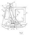
- Fig. 2 das Ausführungsbeispiel gemäß Fig. 1 in Seitenansicht in Richtung der Pfeile II-II von Fig. 1;
- Fig. 3 eine Draufsicht (vereinfacht) der Werkzeugmaschine gemäß Fig. 1 in Richtung der Pfeile III-III von Fig. 1.
- Figure 1 shows an embodiment of a machine tool according to the invention in front view.
- Fig. 2 shows the embodiment of Figure 1 in side view in the direction of arrows II-II of Fig. 1.
- 3 is a plan view (simplified) of the machine tool according to FIG. 1 in the direction of arrows III-III of FIG. 1.
In den Figuren bezeichnet 10 insgesamt eine Werkzeugmaschine, beispielsweise ein numerisch gesteuertes Bohr- und Fräszentrum. Die Werkzeugmaschine 10 ist mit einem unlaufenden, geschlossenen Gehäuse 11 versehen, in das Fenster 12 eingelassen sind. An der Vorderseite des Gehäuses 11 dort, wo der Benutzer der Werkzeugmaschine 10 steht, sind Schiebetüren 13 vorgesehen, die während des Bearbeitungsvorganges geschlossen werden können. Im Gehäuse 11 befindet sich ein horizontaler Werkstücktisch 14, dessen zum Benutzer gewandte Seite als Bestückungsseite 15 und dessen zum Spindelstock 20 weisende Seite als Bearbeitungsseite 16 bezeichnet wird. Die Bestückungsseite 15 ist von der Bearbeitungsseite 16 durch eine gedachte Trennlinie 23 getrennt.In the figures, 10 generally designates a machine tool, for example a numerically controlled drilling and milling center. The
Der Werkstücktisch 14 ist auf einer senkrechten Welle 17 montiert, die um eine vertikale Achse 18 verdrehbar ist. Auf dem Werkstücktisch 14 ist auf dessen Bestückungsseite 15 bzw. dessen Bearbeitungsseite 16 jeweils ein Teilapparat 19 bzw. 19a vorgesehen, in den ein in der Figure nicht gezeigtes Werkstück einspannbar ist.The workpiece table 14 is mounted on a
Der Spindelstock 20 ist mit einem Werkzeug 21, beispielsweise einem Bohrer oder einem Fräser versehen und in mehreren Koordinatenachsen verfahrbar, wie mit einem Koordinatenkreuz 22 angedeutet.The
Im Betrieb der Werkzeugmaschine 10 ist im Teilapparat 19a auf der Bearbeitungsseite 16 des Werkstücktisches 14 ein Werkstück angeordnet, das dort vom Werkzeug 21 unter numerischer Steuerung der Werkzeugmaschine 10 bearbeitet wird. Während dieser Bearbeitung kann ein Benutzer der Werkzeugmaschine 10 das zuvor bearbeitete Werkstück aus dem Teilapparat 19, der sich auf der Bestückungsseite 15 des Werkstücktischs 14 befindet, entnehmen und ein neues, noch unbearbeitetes Werkstück dort einsetzen.When the
Hat nun das Werkzeug 21 den Bearbeitungsvorgang beendet, so wird der Werkstücktisch 14 um 180° gedreht und das Spiel wiederholt sich von neuem.If the
Um die Teilapparate 19, 19a einerseits mit Energie zu versorgen, andererseits aber auch Signale von oder zu den Teilapparaten 19, 19a zu führen, sind im Werkstücktisch 14 Kanäle 30, 31 vorgesehen, wie sie in Fig. 1 angedeutet sind. In die Kanäle 30, 31 sind eine erste Leitung 32 und eine zweite Leitung 33 gelegt, wobei nachfolgend unter "Leitung" jede Art von Verbindungsleitung verstanden werden soll, mit der elektrische Ströme, elektrische oder Fluid-Signale, Druckluft, Hydraulikflüssigkeit und dergleichen geführt werden können.In order to supply the
Die Leitungen 32, 33 sind zu einem Anschlußkasten 34 geführt, in den sie näherungsweise horizontal einmünden. Der Anschlußkasten 34 weist zwei Kniestücke 35, 36 auf, die mit zwei nach oben ausmündenden Klemmen 37, 38 versehen sind. An diesen nach oben weisenden Klemmen 37, 38 sind eine dritte Leitung 39 und eine vierte Leitung 40 angeschlossen, die in weitem Bogen zur Oberseite 45 des Gehäuses 11 hin geführt sind.The
Die Oberseite 45 des Gehäuses 11 überspannt ein Portalrahmen 46, der zwei schräge Rahmenschenkel 47 und einen diese verbindenden waagerechten Rahmenschenkel 48 aufweist. In der Mitte des waagerechten Rahmenschenkels 48 sind zwei nach unten weisende Laschen 49, 50 lösbar befestigt. Die Laschen 49, 50 tragen an ihrer Unterseite zwei nach unten weisende Klemmen 51, 52, in die die Leitungen 39, 40 von unten einmünden.The
Von den Klemmen 51, 52 führen eine fünfte Leitung 53 und eine sechste Leitung 54 zu jeweils einem Steckerteil 55 bzw. 56, die Teile einer lösbaren Steckverbindung 57 bzw. 58 sind. Von diesen Steckverbindungen 57, 58 führen wiederum eine siebte Leitung 59 bzw. eine achte Leitung 60 in das Innere der hohl ausgebildeten Rahmenschenkel 47, 48. Von dort treten die Leitungen aus, wie mit einer neunten Leitung 61 in Fig. 2 angedeutet, um zu einem Steuerungskasten der Werkzeugmaschine 10 zu führen.A
Aus der Draufsicht gemäß Fig. 3 erkennt man, daß die Laschen 49, 50 als Befestigungspunkte der Leitungen 39, 40 zu einem Symmetriepunkt 64 symmetrisch angeordnet sind, der unter einem rechten Winkel 65 zur Trennlinie 23 bzw. dem darauf angeordneten Anschlußkasten 34 angeordnet ist.3 that the
In Fig. 3 ist mit 34 der Anschlußkasten in einer ersten Position eingezeichnet und mit 66 ist ein zum Spindelstock 20 sich öffnender Halbkreis angedeutet, entlang dem der Anschlußkasten 34 geführt ist, wenn er zusammen mit dem Werkstücktisch 14 verschwenkt wird, um dann die in Fig. 3 gestrichelt eingezeichnete Position 34ʹ einzunehmen.In Fig. 3 the
Schließlich kann, wie in den Fig. 1 und 2 zu erkennen ist, noch unterhalb des waagerechten Rahmenschenkels 48 und parallel zu diesem ein Rohr 72 an Streben 70, 71 abgehängt sein, um die Leitungen 39, 40 beim Verschwenken des Werkstücktisches 14 sicher außerhalb des Arbeitsbereiches des Spindelstocks 20 zu halten.Finally, as can be seen in FIGS. 1 and 2, a
Man erkennt aus Fig. 2 auch deutlich, daß der Portalrahmen 46 gegenüber der Achse 18 nach vorne in einen Bereich oberhalb der Bestückungsseite 15 versetzt angeordnet ist, auch dies eine Maßnahme, um sicherzustellen, daß die Spindelstock 20 so weit als möglich nach vorne verfahren werden kann, ohne mit dem Leitungssystem in Kollision zu geraten.It can also be clearly seen from FIG. 2 that the
Claims (8)
Applications Claiming Priority (2)
| Application Number | Priority Date | Filing Date | Title |
|---|---|---|---|
| DE3620086 | 1986-06-14 | ||
| DE19863620086 DE3620086A1 (en) | 1986-06-14 | 1986-06-14 | MACHINE TOOL |
Publications (2)
| Publication Number | Publication Date |
|---|---|
| EP0249845A1 true EP0249845A1 (en) | 1987-12-23 |
| EP0249845B1 EP0249845B1 (en) | 1990-11-28 |
Family
ID=6303028
Family Applications (1)
| Application Number | Title | Priority Date | Filing Date |
|---|---|---|---|
| EP87108251A Expired - Lifetime EP0249845B1 (en) | 1986-06-14 | 1987-06-06 | Machine tool |
Country Status (5)
| Country | Link |
|---|---|
| US (1) | US4850764A (en) |
| EP (1) | EP0249845B1 (en) |
| JP (1) | JPH0615127B2 (en) |
| DE (2) | DE3620086A1 (en) |
| ES (1) | ES2019334B3 (en) |
Cited By (1)
| Publication number | Priority date | Publication date | Assignee | Title |
|---|---|---|---|---|
| EP0811464A1 (en) * | 1996-06-05 | 1997-12-10 | Index-Werke Gmbh & Co. Kg Hahn & Tessky | Machine tool |
Families Citing this family (6)
| Publication number | Priority date | Publication date | Assignee | Title |
|---|---|---|---|---|
| DE4211348C2 (en) * | 1992-04-04 | 1994-06-23 | Chiron Werke Gmbh | Power supply line on a machine tool with a turntable |
| JP2814058B2 (en) * | 1993-09-11 | 1998-10-22 | チロン・ヴェルケ・ゲーエムベーハー・ウント・コー・カーゲー | Machine Tools |
| DE19615425C2 (en) | 1996-04-19 | 1998-09-10 | Chiron Werke Gmbh | Machine tool with a turntable |
| DE10235632B4 (en) * | 2002-08-02 | 2009-03-05 | Franz Kessler Gmbh | Motor spindle or main spindle drive for machine tools |
| JP4409867B2 (en) | 2003-07-15 | 2010-02-03 | 株式会社森精機製作所 | Machine tool routing structure |
| DE102016008948A1 (en) * | 2016-07-26 | 2018-02-01 | Fresenius Medical Care Deutschland Gmbh | Rotary feedthrough for a transport device and transport device with a rotary feedthrough and method for transporting objects from workstation to workstation |
Citations (9)
| Publication number | Priority date | Publication date | Assignee | Title |
|---|---|---|---|---|
| US2107578A (en) * | 1937-05-24 | 1938-02-08 | Onsrud Machine Works Inc | Automatic shaping machine |
| US2355082A (en) * | 1938-06-09 | 1944-08-08 | Kearney & Trecker Corp | Machine tool |
| US2668557A (en) * | 1950-03-21 | 1954-02-09 | American Tool Works Co | Conduit system for machine tools |
| US3241454A (en) * | 1963-01-02 | 1966-03-22 | Jr Robert Lee Medley | Contour and profiling machine |
| FR1454405A (en) * | 1964-12-30 | 1966-10-07 | Multi-spindle reproducing lathe | |
| US3797081A (en) * | 1971-09-30 | 1974-03-19 | Albe Sa | Machine for the automatic high-speed, high precision machining of small parts, even those having a complicated form |
| DE2405024A1 (en) * | 1974-02-02 | 1975-08-21 | Keller & Knappich Augsburg | Prodn line car body mfr with variably programmed tools - has working tools set and removed from line by variably programmed robots |
| GB2040244A (en) * | 1978-12-27 | 1980-08-28 | Prodel M | Conveyor machine with stations for assembling and/or machining workpieces |
| JPS57127637A (en) * | 1981-01-30 | 1982-08-07 | Honda Motor Co Ltd | Work clamp operation control apparatus on jig stand |
Family Cites Families (5)
| Publication number | Priority date | Publication date | Assignee | Title |
|---|---|---|---|---|
| US2892388A (en) * | 1951-07-24 | 1959-06-30 | Giddings & Lewis | Multiple line feed for translatable machine elements |
| US3170375A (en) * | 1962-08-03 | 1965-02-23 | Samuel Briskman | Machine tool for milling pinking shear blades |
| US3592095A (en) * | 1968-04-17 | 1971-07-13 | B R G Rue Pasteur Devil Soc | Shears and the like apparatus for cutting sheet material |
| US3841199A (en) * | 1973-03-13 | 1974-10-15 | Acushnet Co | Golf ball dimple milling apparatus |
| DE8316776U1 (en) * | 1983-06-09 | 1983-11-03 | Chiron Werke GmbH, 7200 Tuttlingen | Machine tool table |
-
1986
- 1986-06-14 DE DE19863620086 patent/DE3620086A1/en active Granted
-
1987
- 1987-06-06 EP EP87108251A patent/EP0249845B1/en not_active Expired - Lifetime
- 1987-06-06 DE DE8787108251T patent/DE3766423D1/en not_active Expired - Fee Related
- 1987-06-06 ES ES87108251T patent/ES2019334B3/en not_active Expired - Lifetime
- 1987-06-10 US US07/061,138 patent/US4850764A/en not_active Expired - Lifetime
- 1987-06-11 JP JP62144229A patent/JPH0615127B2/en not_active Expired - Fee Related
Patent Citations (9)
| Publication number | Priority date | Publication date | Assignee | Title |
|---|---|---|---|---|
| US2107578A (en) * | 1937-05-24 | 1938-02-08 | Onsrud Machine Works Inc | Automatic shaping machine |
| US2355082A (en) * | 1938-06-09 | 1944-08-08 | Kearney & Trecker Corp | Machine tool |
| US2668557A (en) * | 1950-03-21 | 1954-02-09 | American Tool Works Co | Conduit system for machine tools |
| US3241454A (en) * | 1963-01-02 | 1966-03-22 | Jr Robert Lee Medley | Contour and profiling machine |
| FR1454405A (en) * | 1964-12-30 | 1966-10-07 | Multi-spindle reproducing lathe | |
| US3797081A (en) * | 1971-09-30 | 1974-03-19 | Albe Sa | Machine for the automatic high-speed, high precision machining of small parts, even those having a complicated form |
| DE2405024A1 (en) * | 1974-02-02 | 1975-08-21 | Keller & Knappich Augsburg | Prodn line car body mfr with variably programmed tools - has working tools set and removed from line by variably programmed robots |
| GB2040244A (en) * | 1978-12-27 | 1980-08-28 | Prodel M | Conveyor machine with stations for assembling and/or machining workpieces |
| JPS57127637A (en) * | 1981-01-30 | 1982-08-07 | Honda Motor Co Ltd | Work clamp operation control apparatus on jig stand |
Cited By (2)
| Publication number | Priority date | Publication date | Assignee | Title |
|---|---|---|---|---|
| EP0811464A1 (en) * | 1996-06-05 | 1997-12-10 | Index-Werke Gmbh & Co. Kg Hahn & Tessky | Machine tool |
| US5896794A (en) * | 1996-06-05 | 1999-04-27 | Index-Werke Gmbh & Co. Kg Hahn & Tessky | Machine tool |
Also Published As
| Publication number | Publication date |
|---|---|
| DE3620086C2 (en) | 1988-05-19 |
| US4850764A (en) | 1989-07-25 |
| DE3766423D1 (en) | 1991-01-10 |
| EP0249845B1 (en) | 1990-11-28 |
| DE3620086A1 (en) | 1987-12-17 |
| ES2019334B3 (en) | 1991-06-16 |
| JPH0615127B2 (en) | 1994-03-02 |
| JPS62297040A (en) | 1987-12-24 |
Similar Documents
| Publication | Publication Date | Title |
|---|---|---|
| DE3502328C2 (en) | ||
| DE3035451C2 (en) | ||
| EP2255907B1 (en) | Machine tool and method for machining workpieces, in particular metal workpieces | |
| DE3921042A1 (en) | MACHINE TOOL | |
| DE102012201728A1 (en) | PALLET CHANGING DEVICE FOR A MACHINE TOOL AND PALLET CHANGING MACHINE | |
| EP0564842B1 (en) | Machine tool with turntable | |
| EP0249845B1 (en) | Machine tool | |
| DE3241844C1 (en) | Punching machine with revolver drum | |
| DE10330909B4 (en) | Machine tool and method for machining workpieces | |
| DE10062842B4 (en) | Device for processing corner joints | |
| WO2005005098A1 (en) | Machine tool having two parallel spindle rows that can be displaced relative to one another | |
| EP0142592A1 (en) | Milling machine for machining crankshafts or the like | |
| EP1216773B1 (en) | Machine-tool, especially milling center | |
| DE19607883A1 (en) | Lathe with several spindles | |
| DE102019003613A1 (en) | Process for processing workpieces made of wood, plastic and the like | |
| DE4022706C2 (en) | Lathe | |
| DE4229521B4 (en) | Method for balancing a rotor | |
| DE3137582A1 (en) | Machine tool adjustable tailstock e.g. for lathe - has centre in carrier axially adjustable and non-rotatable on axially and rotatably actuated axial guide rod | |
| EP0319731A2 (en) | Lathe with axially movable spindle head | |
| DE977621C (en) | Multi-size series of turret lathes | |
| DE2321617C3 (en) | Device for cutting deburring and shaping the tooth ends of gears or the like | |
| DE926828C (en) | Copy lathe with two longitudinal slides | |
| DE598080C (en) | Machine for the automatic processing of cams and cam drums by a milling cutter controlled by an electric button | |
| EP2401104A1 (en) | Device for machining workpieces | |
| DE19535015C2 (en) | Lathe, in particular multi-spindle automatic lathe |
Legal Events
| Date | Code | Title | Description |
|---|---|---|---|
| PUAI | Public reference made under article 153(3) epc to a published international application that has entered the european phase |
Free format text: ORIGINAL CODE: 0009012 |
|
| AK | Designated contracting states |
Kind code of ref document: A1 Designated state(s): CH DE ES FR GB IT LI SE |
|
| 17P | Request for examination filed |
Effective date: 19880304 |
|
| 17Q | First examination report despatched |
Effective date: 19890727 |
|
| GRAA | (expected) grant |
Free format text: ORIGINAL CODE: 0009210 |
|
| AK | Designated contracting states |
Kind code of ref document: B1 Designated state(s): CH DE ES FR GB IT LI SE |
|
| ET | Fr: translation filed | ||
| GBT | Gb: translation of ep patent filed (gb section 77(6)(a)/1977) | ||
| REF | Corresponds to: |
Ref document number: 3766423 Country of ref document: DE Date of ref document: 19910110 |
|
| ITF | It: translation for a ep patent filed |
Owner name: BUGNION S.P.A. |
|
| PLBI | Opposition filed |
Free format text: ORIGINAL CODE: 0009260 |
|
| 26 | Opposition filed |
Opponent name: GROB-WERKE GMBH & CO. KG, Effective date: 19910827 |
|
| PLBN | Opposition rejected |
Free format text: ORIGINAL CODE: 0009273 |
|
| STAA | Information on the status of an ep patent application or granted ep patent |
Free format text: STATUS: OPPOSITION REJECTED |
|
| PGFP | Annual fee paid to national office [announced via postgrant information from national office to epo] |
Ref country code: SE Payment date: 19920624 Year of fee payment: 6 |
|
| ITTA | It: last paid annual fee | ||
| 27O | Opposition rejected |
Effective date: 19920208 |
|
| PGFP | Annual fee paid to national office [announced via postgrant information from national office to epo] |
Ref country code: CH Payment date: 19920826 Year of fee payment: 6 |
|
| PG25 | Lapsed in a contracting state [announced via postgrant information from national office to epo] |
Ref country code: SE Effective date: 19930607 |
|
| PG25 | Lapsed in a contracting state [announced via postgrant information from national office to epo] |
Ref country code: LI Effective date: 19930630 Ref country code: CH Effective date: 19930630 |
|
| REG | Reference to a national code |
Ref country code: CH Ref legal event code: PL |
|
| EUG | Se: european patent has lapsed |
Ref document number: 87108251.7 Effective date: 19940110 |
|
| REG | Reference to a national code |
Ref country code: GB Ref legal event code: IF02 |
|
| PGFP | Annual fee paid to national office [announced via postgrant information from national office to epo] |
Ref country code: GB Payment date: 20020605 Year of fee payment: 16 |
|
| PGFP | Annual fee paid to national office [announced via postgrant information from national office to epo] |
Ref country code: FR Payment date: 20020627 Year of fee payment: 16 |
|
| PG25 | Lapsed in a contracting state [announced via postgrant information from national office to epo] |
Ref country code: GB Free format text: LAPSE BECAUSE OF NON-PAYMENT OF DUE FEES Effective date: 20030606 |
|
| GBPC | Gb: european patent ceased through non-payment of renewal fee |
Effective date: 20030606 |
|
| PG25 | Lapsed in a contracting state [announced via postgrant information from national office to epo] |
Ref country code: FR Free format text: LAPSE BECAUSE OF NON-PAYMENT OF DUE FEES Effective date: 20040227 |
|
| REG | Reference to a national code |
Ref country code: FR Ref legal event code: ST |
|
| PGFP | Annual fee paid to national office [announced via postgrant information from national office to epo] |
Ref country code: ES Payment date: 20050615 Year of fee payment: 19 |
|
| PGFP | Annual fee paid to national office [announced via postgrant information from national office to epo] |
Ref country code: DE Payment date: 20050726 Year of fee payment: 19 |
|
| PG25 | Lapsed in a contracting state [announced via postgrant information from national office to epo] |
Ref country code: ES Free format text: LAPSE BECAUSE OF NON-PAYMENT OF DUE FEES Effective date: 20060607 |
|
| PGFP | Annual fee paid to national office [announced via postgrant information from national office to epo] |
Ref country code: IT Payment date: 20060630 Year of fee payment: 20 |
|
| PG25 | Lapsed in a contracting state [announced via postgrant information from national office to epo] |
Ref country code: DE Free format text: LAPSE BECAUSE OF NON-PAYMENT OF DUE FEES Effective date: 20070103 |
|
| REG | Reference to a national code |
Ref country code: ES Ref legal event code: FD2A Effective date: 20060607 |