EP0249825B1 - Dispositif pour mesurer l'impédance de tissus corporels - Google Patents
Dispositif pour mesurer l'impédance de tissus corporels Download PDFInfo
- Publication number
- EP0249825B1 EP0249825B1 EP87108122A EP87108122A EP0249825B1 EP 0249825 B1 EP0249825 B1 EP 0249825B1 EP 87108122 A EP87108122 A EP 87108122A EP 87108122 A EP87108122 A EP 87108122A EP 0249825 B1 EP0249825 B1 EP 0249825B1
- Authority
- EP
- European Patent Office
- Prior art keywords
- frequency
- signal
- low
- signal components
- frequency signal
- Prior art date
- Legal status (The legal status is an assumption and is not a legal conclusion. Google has not performed a legal analysis and makes no representation as to the accuracy of the status listed.)
- Expired - Lifetime
Links
- 238000002847 impedance measurement Methods 0.000 title claims description 8
- 238000012937 correction Methods 0.000 claims description 14
- 230000000638 stimulation Effects 0.000 claims description 11
- 238000011156 evaluation Methods 0.000 claims description 6
- 230000001419 dependent effect Effects 0.000 claims description 4
- 230000029058 respiratory gaseous exchange Effects 0.000 claims description 4
- 238000007493 shaping process Methods 0.000 claims description 3
- 230000005540 biological transmission Effects 0.000 claims description 2
- 230000000694 effects Effects 0.000 claims 4
- 238000001914 filtration Methods 0.000 claims 1
- 238000005259 measurement Methods 0.000 description 3
- 239000008280 blood Substances 0.000 description 2
- 210000004369 blood Anatomy 0.000 description 2
- 230000000747 cardiac effect Effects 0.000 description 2
- 238000010586 diagram Methods 0.000 description 2
- 230000000737 periodic effect Effects 0.000 description 2
- 238000007796 conventional method Methods 0.000 description 1
- 230000007423 decrease Effects 0.000 description 1
- 230000010247 heart contraction Effects 0.000 description 1
- 238000000926 separation method Methods 0.000 description 1
- 239000000126 substance Substances 0.000 description 1
Images

Classifications
-
- A—HUMAN NECESSITIES
- A61—MEDICAL OR VETERINARY SCIENCE; HYGIENE
- A61B—DIAGNOSIS; SURGERY; IDENTIFICATION
- A61B5/00—Measuring for diagnostic purposes; Identification of persons
- A61B5/05—Detecting, measuring or recording for diagnosis by means of electric currents or magnetic fields; Measuring using microwaves or radio waves
- A61B5/053—Measuring electrical impedance or conductance of a portion of the body
- A61B5/0535—Impedance plethysmography
-
- A—HUMAN NECESSITIES
- A61—MEDICAL OR VETERINARY SCIENCE; HYGIENE
- A61N—ELECTROTHERAPY; MAGNETOTHERAPY; RADIATION THERAPY; ULTRASOUND THERAPY
- A61N1/00—Electrotherapy; Circuits therefor
- A61N1/18—Applying electric currents by contact electrodes
- A61N1/32—Applying electric currents by contact electrodes alternating or intermittent currents
- A61N1/36—Applying electric currents by contact electrodes alternating or intermittent currents for stimulation
- A61N1/362—Heart stimulators
- A61N1/365—Heart stimulators controlled by a physiological parameter, e.g. heart potential
- A61N1/36514—Heart stimulators controlled by a physiological parameter, e.g. heart potential controlled by a physiological quantity other than heart potential, e.g. blood pressure
- A61N1/36521—Heart stimulators controlled by a physiological parameter, e.g. heart potential controlled by a physiological quantity other than heart potential, e.g. blood pressure the parameter being derived from measurement of an electrical impedance
Definitions
- the invention relates to a device for impedance measurement on body tissues according to the preamble of patent claim 1.
- Such a device with an evaluation device in the sense of the separation of only higher-frequency signal components is e.g. in connection with frequency-controlled pacemakers previously known from US-PS 43 03 075. previously known by US-PS 35 32 088.
- the low frequency component is a measure of the blood volume.
- Impedance measurements in body tissue have so far been used to determine mechanical volume changes in the body, for example the stroke volume of the heart and also breathing due to chest movements.
- the change in impedance can be used to control the frequency of pacemakers.
- the changes in the impedance ⁇ R are a measure of respiration or a measure of the stroke volume of the heart.
- the measurement of periodic impedance fluctuations ⁇ R essentially detects the changes ⁇ 1 of 1 or ⁇ F of F on the line section and thus the changes ⁇ K1.
- it is also dependent on changes ⁇ R in the master value, since the relationship (1) applies:
- the object of the present invention is to develop a device for impedance measurement of the type mentioned at the outset in such a way that when measuring periodic impedance fluctuations, there are no longer any falsifications of measurements due to the influence of changes in the conductance.
- the invention is based on the knowledge that low-frequency signal components of the impedance signal are also a measure of the conductance (that is to say reflect changes in conductance), while, as is known, the higher-frequency signal components essentially reflect changes in I and F.
- the higher-frequency components can be corrected with the low-frequency component and thus an impedance measurement value can be obtained which is unaffected by changes in the conductance value and is therefore much more precise than an impedance measurement value determined by conventional methods.
- the corrected measured value is fed as a control signal to the frequency control part of a frequency-controlled cardiac pacemaker for controlling the stimulation frequency in the sense that the stimulation frequency is changed accordingly when the measured value changes.
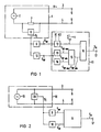
- the impedance meter 1 of FIG. 1 comprises an AC voltage generator 2 (e.g. 1 kHz AC voltage generator) as a signal source for impressing an electrical signal, which, via electrode lines 3 and 4 with associated electrodes 5 and 6, a (not shown) body tissue a constant AC voltage V ⁇ (e.g. 1 kHz alternating voltage).
- the measuring arrangement of FIG. 1 is preferably designed for intracorporeal measurement. So at least the electrodes 5 and 6 are implanted in the body tissue; however, the entire measuring device is preferably implanted.
- the voltage drop caused by the current in the electrode lines 3 and 4 is detected by means of a voltmeter 8 via a low-resistance series resistor 7 (for example 100 ohms).
- the output signal of the voltmeter 8 is then fed to an evaluation device with a low-pass filter 9 and a band-pass filter 10.
- the upper limit frequency of the low-pass filter 9 is in the range 0.1 to 0.4 Hz.
- the low-pass filter 9 only separates from the output signal S I (impedance signal) of the voltmeter 8 the low-frequency signal components S NF which correspond to the conductance ⁇ R in the body tissue .
- the band-pass filter 10 which can be set to a frequency range of 0.2 to 0.6 Hz for detecting breathing or a frequency of 1 to 3 Hz for recording the heart's beating volume, detects the higher frequencies in the band range from the impedance signal S I Signal components S HF of the impedance signal.
- the two signal components S NF and S HF are then fed to a correction device 11, which corrects the higher-frequency signal components S HF with the low-frequency signal components S NF in the sense of freeing the higher-frequency signal components from being influenced by conductance changes ⁇ ⁇ R.
- the correction device 11 comprises a shaping element 12, which converts the low-frequency signal components S NF into a signal as a function of inputable variables K1 and K2 with the following relationship reshaped.
- size K1 takes into account the geometry of the electrode arrangement 5, 6 in patients of different sizes
- size K2 takes into account the type of transmission path between the electrodes 5 and 6 (type of body substance, such as, for example, bony or softer tissue).
- the correction device 11 also includes a peak detector device 13, 14 for the peaks S HF max and S HF min of the high-frequency signal components S HF .
- a difference generator 15 forms the difference S HF max - S HF min .
- a multiplier 16 the signal S HF max - S HF min with the correction signal multiplied. The result is a corrected signal S K at the signal output 17 of the correction device 11.
- the impedance meter 18 comprises an alternating current source 19 (eg 1 kHz alternating current source) which impresses a constant alternating current I ⁇ (eg 1 kHz alternating current) on the body tissue via the electrode lines 3 and 4 and the associated electrodes 5 and 6.
- the entire measuring system is again preferably designed as an intracorporeal measuring system.
- the AC voltage between the electrodes 5 and 6 is measured by means of a voltage meter 20 connected in parallel, which includes a divider to form 1 / V ⁇ .
- the output signal S I (impedance signal) of the voltmeter 20 is then evaluated in the same manner as previously described in connection with FIG. 1 in a filter device 9, 10 with a correction device 11 connected downstream.
- FIG. 3 shows the use of a measuring arrangement according to FIG. 1 or FIG. 2 in a frequency-controlled pacemaker 21.
- the same components are provided with the same reference numbers.
- the electrode 5 is in the in the present case, the stimulation electrode of the pacemaker 21 at the same time, while the electrode 6 is formed by the conductive (for example metallic) housing of the pacemaker.
- the electrode line 3 corresponds to the stimulation catheter of the pacemaker.
- the frequency-controlled cardiac pacemaker 21 comprises a pulse generator 22 for the stimulation pulses 23.
- the repetition rate of the stimulation pulses 23 (stimulation frequency) can be controlled on the pulse generator 22 via a frequency control part 24 as a function of the corrected signal S K at the output 17 of the correction device 11 in the sense that changing signal S K the stimulation frequency is changed accordingly.
- the stimulation rate increases when S K increases. It decreases when S K gets smaller.
Landscapes
- Health & Medical Sciences (AREA)
- Life Sciences & Earth Sciences (AREA)
- Heart & Thoracic Surgery (AREA)
- Cardiology (AREA)
- Hematology (AREA)
- Veterinary Medicine (AREA)
- Biophysics (AREA)
- Engineering & Computer Science (AREA)
- Biomedical Technology (AREA)
- Nuclear Medicine, Radiotherapy & Molecular Imaging (AREA)
- Radiology & Medical Imaging (AREA)
- Animal Behavior & Ethology (AREA)
- General Health & Medical Sciences (AREA)
- Public Health (AREA)
- Physiology (AREA)
- Physics & Mathematics (AREA)
- Pathology (AREA)
- Medical Informatics (AREA)
- Molecular Biology (AREA)
- Surgery (AREA)
- Measurement And Recording Of Electrical Phenomena And Electrical Characteristics Of The Living Body (AREA)
- Electrotherapy Devices (AREA)
- Measurement Of The Respiration, Hearing Ability, Form, And Blood Characteristics Of Living Organisms (AREA)
- Investigating Or Analyzing Materials By The Use Of Electric Means (AREA)
Claims (10)
- Dispositif pour mesurer l'impédance de tissus corporels et comportant une source de signaux (2,19) servant à injecter un signal électrique dans le tissu corporel, un dispositif (1,18) disposé sur le tissu corporel et comportant des électrodes (5,6) et servant à détecter un signal d'impédance SI à partir du tissu corporel en fonction d'un signal électrique injecté, et un dispositif d'évaluation (9,10), qui, pour l'évaluation du signal d'impédance SI, extrait, de ce signal d'impédance, des composantes à basse fréquence et à fréquence supérieure SNF et SHF, et dans lequel, étant donné que le signal d'impédance SI dépend des variation ΔσR de la conductance σR du tissu corporel et des variations ΔK1 de la géométrie K1 du dispositif à électrodes (5,6), le dispositif d'évaluation (9,10) est agencé de manière à extraire des composantes de signal à basse fréquence (SNF), qui dépendent uniquement des variations ΔσR de conductance σR, caractérisé par le fait qu'il est prévu un dispositif de correction (11), qui corrige les composantes de signal à fréquence supérieure SHF, qui sont proportionnelles à

- Dispositif selon la revendication 1, caractérisé par le fait que le dispositif d'évaluation (9,10) comprend un filtre passe-bas (9) pour les composantes de signal à basse fréquence SNF, qui dépendent des variations ΔσR de la conductance.
- Dispositif suivant la revendication 2, caractérisé par le fait que le filtre passe-bas (9) possède une fréquence limite supérieure, située dans la plage de 0,1 à 0,7 Hz.
- Dispositif suivant l'une des revendications 1 à 3, caractérisé par le fait que le dispositif d'évaluation (9,10) comprend un filtre passe-bande (10) pour les composantes de signal à fréquence supérieure SHF.
- Dispositif suivant la revendication 4, caractérisé par le fait que le filtre passe-bande (10) peut être réglé pour détecter l'aspiration dans une plage de fréquences allant de 0,2 jusqu'à 0,6 Hz et que la fréquence limite supérieure du filtre passe-bande (9) est inférieure ou égale à 0,2 Hz.
- Dispositif suivant la revendication 4 ou 5, caractérisé par le fait que le filtre passe-bande (10) peut être réglé à une fréquence comprise entre 1 et 3 Hz, pour une mesure de l'amplitude du battement cardiaque.
- Dispositif suivant l'une des revendications 1 à 6, caractérisé par le fait que le dispositif de correction (11) est agencé de manière à corriger les composantes de signal à fréquence supér SHF avec les composantes de signal à basse fréquence SNF conformément à la relation

- Dispositif suivant la revendication 7, caractérisé par le fait que dans le dispositif de correction (11), un circuit de conversion (12), qui convertit les composantes de signal à basse fréquence SNF conformément à la relation

- Dispositif suivant la revendication 8, caractérisé par le fait que le circuit de conversion (12) et le dispositif (13-15) servant à former la différence valeur maximale/valeur minimale sont raccordés, par l'intermédiaire d'un multiplexeur (16) pour la formation du produit de la différence valeur maximale/valeur minimale SHF max - SHF min et du signal

- Dispositif suivant l'une des revendications 1 à 9, caractérisé par le fait que la sortie (17) du signal du dispositif d'évaluation (11) envoie le signal de correction Sk en tant que signal de commande à la partie (4) de commande de la fréquence d'un stimulateur cardiaque (21) dont la fréquence est commandée, pour réaliser la commande de la fréquence de stimulation de manière à modifier de façon correspondante cette fréquence de stimulation dans le cas où le signal de correction SK varie.
Applications Claiming Priority (2)
| Application Number | Priority Date | Filing Date | Title |
|---|---|---|---|
| DE3620276 | 1986-06-16 | ||
| DE3620276 | 1986-06-16 |
Publications (2)
| Publication Number | Publication Date |
|---|---|
| EP0249825A1 EP0249825A1 (fr) | 1987-12-23 |
| EP0249825B1 true EP0249825B1 (fr) | 1991-11-06 |
Family
ID=6303138
Family Applications (1)
| Application Number | Title | Priority Date | Filing Date |
|---|---|---|---|
| EP87108122A Expired - Lifetime EP0249825B1 (fr) | 1986-06-16 | 1987-06-04 | Dispositif pour mesurer l'impédance de tissus corporels |
Country Status (4)
| Country | Link |
|---|---|
| US (1) | US4823797A (fr) |
| EP (1) | EP0249825B1 (fr) |
| JP (1) | JPH0832263B2 (fr) |
| DE (1) | DE3774332D1 (fr) |
Families Citing this family (41)
| Publication number | Priority date | Publication date | Assignee | Title |
|---|---|---|---|---|
| CN1024161C (zh) * | 1987-09-05 | 1994-04-13 | 哈尔滨工业大学 | 检测和处理阻抗血流图的方法及装置 |
| DE3732640C1 (de) * | 1987-09-28 | 1989-05-18 | Alt Eckhard | Medizinisches Geraet zum Ermitteln von physiologischen Funktionsparametern |
| GB2214813A (en) * | 1988-01-14 | 1989-09-13 | Stuart Charles Webb | Rate-responsive pacemaker |
| WO1989006990A1 (fr) * | 1988-02-05 | 1989-08-10 | Siemens Aktiengesellschaft | Circuit de regulation pour adapter la frequence de stimulation d'un stimulateur cardiaque a l'effort d'un patient |
| US5027813A (en) * | 1990-03-05 | 1991-07-02 | Cardiac Pacemakers, Inc. | Rate responsive pacemaker apparatus having an electrode interface sensor |
| US5058583A (en) * | 1990-07-13 | 1991-10-22 | Geddes Leslie A | Multiple monopolar system and method of measuring stroke volume of the heart |
| US5063937A (en) * | 1990-09-12 | 1991-11-12 | Wright State University | Multiple frequency bio-impedance measurement system |
| US5309917A (en) * | 1991-09-12 | 1994-05-10 | Drexel University | System and method of impedance cardiography and heartbeat determination |
| US5376103A (en) * | 1992-03-19 | 1994-12-27 | Angeion Corporation | Electrode system for implantable defibrillator |
| US5282840A (en) * | 1992-03-26 | 1994-02-01 | Medtronic, Inc. | Multiple frequency impedance measurement system |
| EP0573684B1 (fr) * | 1992-06-09 | 1997-12-17 | Pacesetter AB | Procédé et dispositif de détection d'un paramètre fonctionnel physiologique d'un être vivant |
| US5735284A (en) * | 1992-06-24 | 1998-04-07 | N.I. Medical Ltd. | Method and system for non-invasive determination of the main cardiorespiratory parameters of the human body |
| US5271413A (en) * | 1992-07-22 | 1993-12-21 | Dalamagas Photios P | Method to sense the tissue for injection from a hypodermic needle |
| US5454377A (en) * | 1993-10-08 | 1995-10-03 | The Ohio State University | Method for measuring the myocardial electrical impedance spectrum |
| US5524632A (en) * | 1994-01-07 | 1996-06-11 | Medtronic, Inc. | Method for implanting electromyographic sensing electrodes |
| US5800470A (en) * | 1994-01-07 | 1998-09-01 | Medtronic, Inc. | Respiratory muscle electromyographic rate responsive pacemaker |
| US6560480B1 (en) | 1994-10-24 | 2003-05-06 | Transscan Medical Ltd. | Localization of anomalies in tissue and guidance of invasive tools based on impedance imaging |
| US5810742A (en) * | 1994-10-24 | 1998-09-22 | Transcan Research & Development Co., Ltd. | Tissue characterization based on impedance images and on impedance measurements |
| US6678552B2 (en) | 1994-10-24 | 2004-01-13 | Transscan Medical Ltd. | Tissue characterization based on impedance images and on impedance measurements |
| US5623938A (en) * | 1995-09-29 | 1997-04-29 | Siemens Medical Systems, Inc. | Method and apparatus for respiration monitoring |
| RU2094013C1 (ru) * | 1996-04-29 | 1997-10-27 | Николаев Дмитрий Викторович | Способ региональной биоимпедансометрии и устройство для его осуществления |
| US5732710A (en) * | 1996-08-09 | 1998-03-31 | R.S. Medical Monitoring Ltd. | Method and device for stable impedance plethysmography |
| US5749369A (en) * | 1996-08-09 | 1998-05-12 | R.S. Medical Monitoring Ltd. | Method and device for stable impedance plethysmography |
| US6310512B1 (en) | 1999-11-22 | 2001-10-30 | Cardiac Pacemakers, Inc. | Integrated self-adjustable continuous time band pass filter based upon Gm cell with bipolar transistors |
| US6287263B1 (en) * | 1999-02-08 | 2001-09-11 | Cardiac Pacemakers, Inc. | System for processing bursted amplitude modulated signals using an impedance sensor |
| CN1091490C (zh) * | 1999-06-28 | 2002-09-25 | 孙祺 | 发动机供气方法及其供气装置 |
| US6564079B1 (en) | 2000-07-27 | 2003-05-13 | Ckm Diagnostics, Inc. | Electrode array and skin attachment system for noninvasive nerve location and imaging device |
| WO2003084397A2 (fr) | 2002-04-04 | 2003-10-16 | Transscan Medical Ltd. | Depistage du cancer du sein |
| US7986994B2 (en) | 2002-12-04 | 2011-07-26 | Medtronic, Inc. | Method and apparatus for detecting change in intrathoracic electrical impedance |
| CA2583526A1 (fr) * | 2004-03-24 | 2005-10-13 | Noninvasive Medical Technologies, Llc | Moniteur de l'impedance thoracique et reseau d'electrodes et procede d'utilisation |
| CN1319490C (zh) * | 2005-07-01 | 2007-06-06 | 天津大学 | 模拟解调方式的混频生物阻抗测量系统 |
| US8948868B2 (en) * | 2006-10-31 | 2015-02-03 | Medtronic, Inc. | Methods and apparatus for manually suspending intrathoracic impedance fluid status measurements |
| US8255046B2 (en) * | 2008-07-31 | 2012-08-28 | Medtronic, Inc. | Detecting worsening heart failure based on impedance measurements |
| US9713701B2 (en) | 2008-07-31 | 2017-07-25 | Medtronic, Inc. | Using multiple diagnostic parameters for predicting heart failure events |
| US8632473B2 (en) * | 2009-01-30 | 2014-01-21 | Medtronic, Inc. | Detecting worsening heart failure based on fluid accumulation with respiratory confirmation |
| US8271072B2 (en) * | 2009-10-30 | 2012-09-18 | Medtronic, Inc. | Detecting worsening heart failure |
| US8731657B1 (en) * | 2011-07-05 | 2014-05-20 | TAMA Research Corp. | Multi-mode microcurrent stimulus system with safety circuitry and related methods |
| US10952686B2 (en) | 2016-08-02 | 2021-03-23 | Medtronic, Inc. | Mobile application to prompt physical action to measure physiologic response in implantable device |
| JP7156739B2 (ja) * | 2019-04-18 | 2022-10-19 | 麦層移動健康管理有限公司 | 心筋組織の運動特徴を測定するための非侵襲的方法及びシステム |
| US11717186B2 (en) | 2019-08-27 | 2023-08-08 | Medtronic, Inc. | Body stability measurement |
| US11602313B2 (en) | 2020-07-28 | 2023-03-14 | Medtronic, Inc. | Determining a fall risk responsive to detecting body position movements |
Family Cites Families (10)
| Publication number | Priority date | Publication date | Assignee | Title |
|---|---|---|---|---|
| US3532086A (en) * | 1966-02-23 | 1970-10-06 | Research Corp | Method and apparatus for determining blood loss of patients |
| US3608542A (en) * | 1970-06-12 | 1971-09-28 | Beckman Instruments Inc | Physiological monitoring system |
| US3994284A (en) * | 1975-12-31 | 1976-11-30 | Systron Donner Corporation | Flow rate computer adjunct for use with an impedance plethysmograph and method |
| US4291699A (en) * | 1978-09-21 | 1981-09-29 | Purdue Research Foundation | Method of and apparatus for automatically detecting and treating ventricular fibrillation |
| JPS5639221A (en) * | 1979-09-01 | 1981-04-14 | Sugiaki Kusatake | Connected blocks for bank protection where fish nest is formed |
| US4303075A (en) * | 1980-02-11 | 1981-12-01 | Mieczyslaw Mirowski | Method and apparatus for maximizing stroke volume through atrioventricular pacing using implanted cardioverter/pacer |
| US4686987A (en) * | 1981-06-18 | 1987-08-18 | Cardiac Pacemakers, Inc. | Biomedical method and apparatus for controlling the administration of therapy to a patient in response to changes in physiologic demand |
| US4580575A (en) * | 1982-06-14 | 1986-04-08 | Aequitron Medical, Inc. | Apnea monitoring system |
| US4738264A (en) * | 1985-03-25 | 1988-04-19 | Carl Orlando | Heart and breathing alarm monitor |
| US4697591A (en) * | 1986-06-16 | 1987-10-06 | Siemens Aktiengesellschaft | Cardiac pacer for pacing a human heart and pacing method |
-
1987
- 1987-06-04 DE DE8787108122T patent/DE3774332D1/de not_active Expired - Lifetime
- 1987-06-04 EP EP87108122A patent/EP0249825B1/fr not_active Expired - Lifetime
- 1987-06-11 JP JP62146191A patent/JPH0832263B2/ja not_active Expired - Lifetime
- 1987-06-15 US US07/061,547 patent/US4823797A/en not_active Expired - Lifetime
Also Published As
| Publication number | Publication date |
|---|---|
| US4823797A (en) | 1989-04-25 |
| EP0249825A1 (fr) | 1987-12-23 |
| JPS633839A (ja) | 1988-01-08 |
| DE3774332D1 (de) | 1991-12-12 |
| JPH0832263B2 (ja) | 1996-03-29 |
Similar Documents
| Publication | Publication Date | Title |
|---|---|---|
| EP0249825B1 (fr) | Dispositif pour mesurer l'impédance de tissus corporels | |
| EP0249823B1 (fr) | Dispositif pour le contrôle d'un stimulateur cardiaque intracorporel utilisant la mesure de l'impedance de tissus corporels | |
| DE69110710T3 (de) | Bedarfsherzschrittmacher mit einem kapazitiven Filter, dessen Grenzfrequenz durch den Herzrhythmus bestimmt wird. | |
| DE69525561T2 (de) | Vorrichtung zur Erkennung hämodynamischer Zustände eines Herzens | |
| DE102014219943B4 (de) | Schaltungsanordnung zur Unterdrückung von Gleichtaktstörsignalen bei der Messung von bioelektrischen Signalen | |
| DE3854732T2 (de) | Physiologische Herz- und Lungenuntersuchung durch intrakardielle Messungen mit einem einzelnen Sensor. | |
| DE60025486T2 (de) | Anpassbare evozierte herzreaktionsmessvorrichtung für automatische erregungsbestätigung | |
| EP0226164B1 (fr) | Stimulateur cardiaque | |
| DE69423674T2 (de) | Verfahren und Vorrichtung zur Uberwachung von Herzschrittmacherelektroden | |
| DE2349624A1 (de) | Impedanz-plethysmograph | |
| DE2910944C2 (fr) | ||
| DE69010251T2 (de) | Dentale Einheit zur Behandlung eines Wurzelkanals. | |
| DE555988T1 (de) | Durch einpolige Messung der vom Minutenvolumen abhängigen Impedanz gesteuerter Herzschrittmacher. | |
| EP0212370A2 (fr) | Surveillance de la respiration | |
| EP0000504A1 (fr) | Circuit de commutation électrique pour la détection et l'enregistrement de l'activité de la matrice | |
| EP0218007B1 (fr) | Stimulateur cardiaque | |
| DE69018924T2 (de) | Verfahren zur Unterscheidung von Herz-Impulsenden. | |
| WO1997009928A1 (fr) | Procede et dispositif pour la determination du debit cardiaque | |
| EP1955650A2 (fr) | Appareil médical implantable | |
| DE2661005C2 (fr) | ||
| EP0584388B1 (fr) | Stimulateur cardiaque de production d'un signal correspondant au volume-par-minute d'un patient | |
| EP0026479B1 (fr) | Dispositif électro-médical | |
| DE2104850C3 (de) | Schaltungsanordnung zur Überprüfung des Elektroden-Übergangswiderstandes während der Registrierung von mittels Differenzverstärkern verstärkten bioelektrischen Signalen | |
| DE19900690C1 (de) | Herzschrittmacher | |
| EP0574464B1 (fr) | Procede et dispositif pour l'extraction par filtrage d'oscillations de la ligne de base dans un electrocardiogramme |
Legal Events
| Date | Code | Title | Description |
|---|---|---|---|
| PUAI | Public reference made under article 153(3) epc to a published international application that has entered the european phase |
Free format text: ORIGINAL CODE: 0009012 |
|
| AK | Designated contracting states |
Kind code of ref document: A1 Designated state(s): DE FR GB IT NL SE |
|
| 17P | Request for examination filed |
Effective date: 19880125 |
|
| 17Q | First examination report despatched |
Effective date: 19900508 |
|
| GRAA | (expected) grant |
Free format text: ORIGINAL CODE: 0009210 |
|
| AK | Designated contracting states |
Kind code of ref document: B1 Designated state(s): DE FR GB IT NL SE |
|
| PG25 | Lapsed in a contracting state [announced via postgrant information from national office to epo] |
Ref country code: SE Effective date: 19911106 |
|
| REF | Corresponds to: |
Ref document number: 3774332 Country of ref document: DE Date of ref document: 19911212 |
|
| ET | Fr: translation filed | ||
| ITF | It: translation for a ep patent filed | ||
| GBT | Gb: translation of ep patent filed (gb section 77(6)(a)/1977) | ||
| PLBI | Opposition filed |
Free format text: ORIGINAL CODE: 0009260 |
|
| 26 | Opposition filed |
Opponent name: BIOTRONIK MESS- UND THERAPIEGERAETE GMBH & CO ING Effective date: 19920806 |
|
| NLR1 | Nl: opposition has been filed with the epo |
Opponent name: BIOTRONIK MESS-UND THERAPIEGERAETE GMBH & CO INGEN |
|
| ITPR | It: changes in ownership of a european patent |
Owner name: CESSIONE;PACESETTER AB |
|
| REG | Reference to a national code |
Ref country code: GB Ref legal event code: 732E |
|
| REG | Reference to a national code |
Ref country code: FR Ref legal event code: TP |
|
| NLS | Nl: assignments of ep-patents |
Owner name: PACESETTER AB |
|
| RAP2 | Party data changed (patent owner data changed or rights of a patent transferred) |
Owner name: PACESETTER AB |
|
| NLT2 | Nl: modifications (of names), taken from the european patent patent bulletin |
Owner name: PACESETTER AB |
|
| APAC | Appeal dossier modified |
Free format text: ORIGINAL CODE: EPIDOS NOAPO |
|
| PLBN | Opposition rejected |
Free format text: ORIGINAL CODE: 0009273 |
|
| STAA | Information on the status of an ep patent application or granted ep patent |
Free format text: STATUS: OPPOSITION REJECTED |
|
| 27O | Opposition rejected |
Effective date: 19960515 |
|
| NLR2 | Nl: decision of opposition | ||
| PGFP | Annual fee paid to national office [announced via postgrant information from national office to epo] |
Ref country code: GB Payment date: 19980515 Year of fee payment: 12 |
|
| PG25 | Lapsed in a contracting state [announced via postgrant information from national office to epo] |
Ref country code: GB Free format text: LAPSE BECAUSE OF NON-PAYMENT OF DUE FEES Effective date: 19990604 |
|
| PGFP | Annual fee paid to national office [announced via postgrant information from national office to epo] |
Ref country code: NL Payment date: 19990621 Year of fee payment: 13 |
|
| GBPC | Gb: european patent ceased through non-payment of renewal fee |
Effective date: 19990604 |
|
| PG25 | Lapsed in a contracting state [announced via postgrant information from national office to epo] |
Ref country code: NL Free format text: LAPSE BECAUSE OF NON-PAYMENT OF DUE FEES Effective date: 20010101 |
|
| NLV4 | Nl: lapsed or anulled due to non-payment of the annual fee |
Effective date: 20010101 |
|
| APAH | Appeal reference modified |
Free format text: ORIGINAL CODE: EPIDOSCREFNO |
|
| PGFP | Annual fee paid to national office [announced via postgrant information from national office to epo] |
Ref country code: DE Payment date: 20060628 Year of fee payment: 20 |
|
| PGFP | Annual fee paid to national office [announced via postgrant information from national office to epo] |
Ref country code: IT Payment date: 20060630 Year of fee payment: 20 Ref country code: FR Payment date: 20060630 Year of fee payment: 20 |