EP0249768A2 - Contrôle d'interface pour un semi-conducteur à un composé - Google Patents
Contrôle d'interface pour un semi-conducteur à un composé Download PDFInfo
- Publication number
- EP0249768A2 EP0249768A2 EP87107476A EP87107476A EP0249768A2 EP 0249768 A2 EP0249768 A2 EP 0249768A2 EP 87107476 A EP87107476 A EP 87107476A EP 87107476 A EP87107476 A EP 87107476A EP 0249768 A2 EP0249768 A2 EP 0249768A2
- Authority
- EP
- European Patent Office
- Prior art keywords
- oxide
- compound semiconductor
- cationic
- metal
- anion
- Prior art date
- Legal status (The legal status is an assumption and is not a legal conclusion. Google has not performed a legal analysis and makes no representation as to the accuracy of the status listed.)
- Ceased
Links
Images


Classifications
-
- H10P14/6312—
-
- H—ELECTRICITY
- H10—SEMICONDUCTOR DEVICES; ELECTRIC SOLID-STATE DEVICES NOT OTHERWISE PROVIDED FOR
- H10D—INORGANIC ELECTRIC SEMICONDUCTOR DEVICES
- H10D30/00—Field-effect transistors [FET]
- H10D30/60—Insulated-gate field-effect transistors [IGFET]
- H10D30/67—Thin-film transistors [TFT]
- H10D30/6729—Thin-film transistors [TFT] characterised by the electrodes
- H10D30/6737—Thin-film transistors [TFT] characterised by the electrodes characterised by the electrode materials
- H10D30/6738—Schottky barrier electrodes
-
- H—ELECTRICITY
- H10—SEMICONDUCTOR DEVICES; ELECTRIC SOLID-STATE DEVICES NOT OTHERWISE PROVIDED FOR
- H10D—INORGANIC ELECTRIC SEMICONDUCTOR DEVICES
- H10D30/00—Field-effect transistors [FET]
- H10D30/60—Insulated-gate field-effect transistors [IGFET]
- H10D30/67—Thin-film transistors [TFT]
- H10D30/674—Thin-film transistors [TFT] characterised by the active materials
- H10D30/675—Group III-V materials, Group II-VI materials, Group IV-VI materials, selenium or tellurium
-
- H—ELECTRICITY
- H10—SEMICONDUCTOR DEVICES; ELECTRIC SOLID-STATE DEVICES NOT OTHERWISE PROVIDED FOR
- H10D—INORGANIC ELECTRIC SEMICONDUCTOR DEVICES
- H10D62/00—Semiconductor bodies, or regions thereof, of devices having potential barriers
- H10D62/80—Semiconductor bodies, or regions thereof, of devices having potential barriers characterised by the materials
- H10D62/83—Semiconductor bodies, or regions thereof, of devices having potential barriers characterised by the materials being Group IV materials, e.g. B-doped Si or undoped Ge
-
- H—ELECTRICITY
- H10—SEMICONDUCTOR DEVICES; ELECTRIC SOLID-STATE DEVICES NOT OTHERWISE PROVIDED FOR
- H10D—INORGANIC ELECTRIC SEMICONDUCTOR DEVICES
- H10D62/00—Semiconductor bodies, or regions thereof, of devices having potential barriers
- H10D62/80—Semiconductor bodies, or regions thereof, of devices having potential barriers characterised by the materials
- H10D62/85—Semiconductor bodies, or regions thereof, of devices having potential barriers characterised by the materials being Group III-V materials, e.g. GaAs
-
- H10D64/01358—
-
- H—ELECTRICITY
- H10—SEMICONDUCTOR DEVICES; ELECTRIC SOLID-STATE DEVICES NOT OTHERWISE PROVIDED FOR
- H10D—INORGANIC ELECTRIC SEMICONDUCTOR DEVICES
- H10D64/00—Electrodes of devices having potential barriers
- H10D64/60—Electrodes characterised by their materials
- H10D64/62—Electrodes ohmically coupled to a semiconductor
-
- H—ELECTRICITY
- H10—SEMICONDUCTOR DEVICES; ELECTRIC SOLID-STATE DEVICES NOT OTHERWISE PROVIDED FOR
- H10D—INORGANIC ELECTRIC SEMICONDUCTOR DEVICES
- H10D64/00—Electrodes of devices having potential barriers
- H10D64/60—Electrodes characterised by their materials
- H10D64/64—Electrodes comprising a Schottky barrier to a semiconductor
-
- H—ELECTRICITY
- H10—SEMICONDUCTOR DEVICES; ELECTRIC SOLID-STATE DEVICES NOT OTHERWISE PROVIDED FOR
- H10D—INORGANIC ELECTRIC SEMICONDUCTOR DEVICES
- H10D64/00—Electrodes of devices having potential barriers
- H10D64/60—Electrodes characterised by their materials
- H10D64/66—Electrodes having a conductor capacitively coupled to a semiconductor by an insulator, e.g. MIS electrodes
- H10D64/68—Electrodes having a conductor capacitively coupled to a semiconductor by an insulator, e.g. MIS electrodes characterised by the insulator, e.g. by the gate insulator
- H10D64/681—Electrodes having a conductor capacitively coupled to a semiconductor by an insulator, e.g. MIS electrodes characterised by the insulator, e.g. by the gate insulator having a compositional variation, e.g. multilayered
- H10D64/685—Electrodes having a conductor capacitively coupled to a semiconductor by an insulator, e.g. MIS electrodes characterised by the insulator, e.g. by the gate insulator having a compositional variation, e.g. multilayered being perpendicular to the channel plane
-
- H10P14/6324—
Definitions
- the technical field of the invention is the formation of semiconductor circuit devices in compound type semiconductor materials.
- the more well known of these materials are composed of elements from Group III and Group V of the periodic table such as gallium arsenide.
- This type of semiconductor exhibits properties at its surface that can produce a barrier to current flow, which in turn interferes with the electrical properties of devices fabricated using these materials.
- Equation 1 The familiar Schottky relationship is expressed in Equation 1 as follows.
- ⁇ bn the barrier height on n type material
- ⁇ m the work function of the metal
- ⁇ sc the electron affinity of the semiconductor which in turn is the energy required to remove an electron from the bottom of the conduction band to vacuum with no kinetic energy.
- MOS Metal Oxide Semiconductor
- MOS structures made from gallium arsenide show that elemental As at the interface plays an important role in determining the electrical properties of the oxide.
- the electrical measurements show that excess elemental As is correlated with large trap densities and fixed states in the oxide.
- the invention is the formation of an anion free ingredient oxide on the surface of a compound semiconductor that eliminates the Fermi level pinning condition, making the compound semiconductor, in structure and performance, responsive to metal work function.
- the anion ingredient of the compound semiconductor itself is excluded.
- the As component of GaAs the As component of GaAs.
- the elemental As and compounds including oxides thereof on the surface that is not part of the GaAs itself is the anion species that is being controlled by providing the anion free cationic ingredient oxide.
- the compound semiconductor is in the form of a single crystal.
- the invention operates to eliminate the Fermi level pinning phenomenon by removing both anion species and all chemical species at the surface which will, upon contact with the semiconductor, cause a reaction that generates anion species and insuring their absence by an ingredient oxide that is cationic. Where Fermi level pinning is desired in a particular structure, some localized anionic content is employed.
- the element of the lower group of the periodic table is always cationic.
- the group III-V compound GaAs the group III, Ga is cationic and in the group II-VI compound CdSe the group II, Cd is cationic.
- a cationic ingredient oxide is formed on the compound semiconductor substrate. This is accomplished by forming oxides containing each ingredient in the compound semiconductor and then removing all the anion containing oxides as well as any elemental anions under conditions that permit the compound semiconductor surface to be covered by a cationic ingredient oxide layer.
- the anion is As
- anion ingredient oxides such as As2O3 and GaAsO4
- cation ingredient oxides of Ga such as Ga2O3.
- the reaction may be expressed as in Equation 2 using the example Group III-V compound semiconductor.
- V ox + III-V III ox + V where III-V is the compound semiconductor V is a Group V element, i.e., As V ox is an oxide of the Group V ingredient, i.e., As2O3 and III ox is an oxide of the Group III ingredient, i.e., Ga2O3
- Equation 2 when the free energy ⁇ F is less than zero, all phases will appear when the reactions start from the left side of the equation. Since ⁇ F is less than zero for most compound semiconductors and since it is known that the presence of V ox and V are detrimental for certain device applications, it is necessary to selectively remove V ox and V so that only III ox remains under equilibrium conditions. In addition, there may be other chemical species that will react with the compound semiconductors to create V or V ox and these must be removed as well, or prevented from contacting the semiconductor by the layer of III ox that is formed.
- the presence of the anionic arsenic oxide and the anion arsenic at the surface interface is the source of the problem, the Fermi level pinning phenomenon.
- anion free cationic ingredient oxide shall be defined as a cationic oxide of the lowest group ingredient of the compound semiconductor that has less than 2% concentration of anion species on the surface.
- the Fermi level pinning is eliminated by providing the surface of the compound semiconductor with a cationic ingredient oxide.
- the oxide layer will be a layer of cationic oxide that is completely free of anionic species.
- localized anionic species may be included in the cationic oxide layer.
- this is accomplished by providing an oxidizing agent during growth that promotes the formation of oxides of each and every ingredient.
- oxides of As, elemental As and oxides of Ga are formed.
- a selective removal agent that operates to remove the anionic species, such as As and the oxides of As, leaving behind the cationic species, the oxides of gallium.
- Such agents are treated in textbooks directed to aqueous solution chemistry, such as "An Atlas of Electrochemical Equilibrium in Aqueous Solutions", published by the National Association of Corrosion Engineers, Houston, Texas 1974, and one skilled in the art in the light of these principles can readily establish the requirements in different material systems.
- light is an agent that promotes oxidation, and oxygenated water will serve as a selective anionic species removal agent, that is to say it dissolves As2O3 and As.
- a substrate 1 of a compound semiconductor for example, GaAs
- the layer 3 is of gallium oxide.
- FIGS. 2 and 3 are energy band diagrams of the interface 2 for n-type GaAs.
- a low work function that is ⁇ m is approximately equal to ⁇ sc , is applied to the surface 4.
- the band edges, in the presence of the anion free, cationic oxide, at the interface 2, commonly known as flat band, will remain level and have approximately the same value as that in the bulk.
- This unpinned energy band diagram is illustrative of conditions preferred for Metal Oxide Semiconductor (MOS) type devices because it facilitates carrier modulation through an electrode 5.
- MOS Metal Oxide Semiconductor
- FIGS. 4 and 5 are energy band diagrams where the cationic oxide layer is of tunneling dimensions of the order of 10 to 50 ⁇ for n type GaAs.
- a low work function metal 5 that is a metal where ⁇ m is approximately equal to ⁇ sc , is applied to the surface 4.
- the band edges in the presence of the anion free cationic oxide at the interface 2 will remain level, commonly known as flat band and will have approximately the same value as that in the bulk.
- This energy band diagram is that for an ideal ohmic contact useful in a large variety of semiconductor device applications.
- cation oxide 3 for example, n type GaAs with a Ga2O3, a low barrier will be produced at interface 2 when surface 4 is coated with a low work function metal 5, for example Al.
- a high barrier will be produced at interface 2 when surface 4 is coated with a high work function metal 5, for example Au.
- anion is locally included in the cation oxide 3 application of a metal 5 with a low work function, for example Al, on surface 4, will result in a high barrier in the region containing the anion whereas there will be a low barrier in the anion free region.
- a metal 5 with a low work function, for example Al on surface 4
- FIG. 6 a diagram is provided illustrating the formation of an anion free cationic ingredient oxide covered compound semiconductor substrates in which, in general, an oxide layer as 3 in FIG. 1 is grown under conditions that produce oxides of all ingredients of the compound semiconductor and essentially simultaneously the growth continues in the presence of an agent that removes the anion species which passes off as an effluent.
- an agent for the oxidation is the combination of light and water and an agent for the selective removal of the As species is flowing oxygenated water. Since flowing water alone will slowly remove gallium oxide, it is necessary that the oxidation rate be larger than the removal rate for oxide growth to occur.
- the resulting substrate has an anion free cationic ingredient oxide covering which then has a resistance to anion oxidation in the shelf time between processing operations.
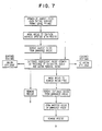
- the pattern may be formed either by selectively removing all anionic species from regions with a desired pattern or by introducing anionic species in a selective pattern. Either process will result in an oxide layer on the surface with areas which have only cationic oxide present and also areas which have localized inclusion of anionic species. This is illustrated in FIG. 7.
- patterned unpinning is achieved by first growing on a substrate, such as a wafer, an anodic oxide by conventional means. Such oxides contain anionic species and exhibit Fermi level pinning.
- Unpinned regions are then formed by masking with a resist the desired to be pinned areas, removing the anodic oxide in the unmasked areas and then growing an unpinned cationic oxide in accordance with the invention.
- the resist is then removed and a wafer having patterned localized anion inclusions on a cationic ingredient oxide is the result.
- FIG. 7 on the right side of the diagram the entire surface is first cleaned.
- An unpinned cationic ingredient oxide layer is then grown in accordance with the invention.
- the areas to remain anion free are then masked.
- the cationic oxide is removed from the unmasked areas followed by removal of the resist so that a substrate having patterned localized anion inclusions is the result.
- FIGS. 8, 9 and 10 illustrations are provided of device structures which utilize the control capabilities achieved by the responsiveness to metal work function of a semiconductor surface with an unpinned Fermi level at an oxide interface.
- a MOSFET type device is illustrated where on a compound semiconductor, for example GaAs, substrate such as 1 in FIG. 1, on the interface 2 a layer of anion free cationic oxide 3 is provided having a thickness compatible with standard signal levels for current influencing in the area of said substrate 1, for example 1000 ⁇ .
- High conductivity n+ source 6 and drain 7 regions are formed with metal external electrodes 8 and 9 to the source 6 and drain 7, respectively, and over the oxide 3, which together with the metal 10 serves as the gate.
- the gate 10 will exhibit the characteristics illustrated in connection with the flat band interface of FIG. 2 rather than the prior art situation of FIG. 3 with the interface states that produce undesirable traps.
- the ohmic contact between the source 6 and metal electrode 8 and drain 7 and metal electrode 9 will exhibit the characteristics illustrated in connection with the flat band interface of FIG. 4 rather than the prior art situation of FIG. 5 where the Fermi level pinning operates to produce a barrier which introduces undesirable resistance into the ohmic contacts.
- a Metal Semiconductor Field Effect Transistor (MESFET) type device is illustrated where on a compound semiconductor, for example GaAs, substrate 11 that is semi-insulating as is standard in the art, there is provided a channel layer 12 of n conductivity type doped to about 2 ⁇ 1017 atoms/cm3 about 1000 ⁇ thick.
- a layer 13 of cationic ingredient oxide is provided on the surface of the layer 12.
- the oxide 13 is of quantum mechanical tunneling thickness, that is approximately 50 ⁇ thick.
- the oxide 13 is cationic and completely free of anion species so that the Fermi level at the surface of the layer 12 is unpinned whereas in the region under the gate 16 the oxide 13 contains a localized inclusion of anion species to produce localized pinning and a selected height barrier.
- the source 14, drain 15 and gate 16 metal are the same low work function ( ⁇ m ) such as Al.
- ⁇ m work function
- the source 8 and drain 9 contacts provide barrier free electrical behavior where the cationic oxide provides the flat band of FIG. 2 yet the oxide 13 being sufficiently thin for quantum mechanical tunneling provides a low impedance contact.
- the localized anion inclusion in the oxide 13 under the gate metal contact 16 permits sufficient band bending that a rectifying gate contact is provided to the field effect transistor.
- FIG. 10 a field effect type transistor is illustrated in which, in accordance with the invention with the Fermi level pinning control oxide, a difference in work function of metal provides structural and performance functions.
- a device layer 18 is provided of n conductivity type doped to the order of 2 ⁇ 1017 atoms/cm3.
- An anion species free cationic ingredient oxide layer 19 that is of the order of 50 ⁇ thick so that quantum mechanical tunneling can occur is provided over the layer 18.
- Source 20 and drain 21 metal contacts are applied using a low work function ( ⁇ m ) metal such as Al. These contacts will exhibit low impedance ohmic behavior because the oxide 19 will insure a flat band surface.
- the gate metal contact 22 is of a metal with a higher work function ( ⁇ m ) than that of the metal used for contacts 20 and 21, for example Au, so that with the oxide 19 the performance is in accordance with Equation 1 and the higher work function metal 22 provides the desired barrier for a field effect transistor gate.
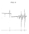
- an Auger electron spectroscopy of the GaAs surface demonstrates the presence of the anion species As.
- GaAs gallium arsenide
- a GaAs wafer has typical 2 ⁇ 1017 atoms/cm3 n conductivity type layer over a semi-insulating substrate. It is first cleaned in hot sulfuric acid and water (1:1) to generate a clean starting surface. The wafer is immersed in flowing oxygenated deionized water and illuminated by an intense light source, such as a quartz halogen projection bulb. An Auger electron spectrum of the resulting cationic ingredient oxide on the surface is shown in FIG. 12 to contain less than 2% anion As species and when compared with FIG. 11, the cationic ingredient oxide is anion free. The wafer exhibits the flat band surface behavior of FIGS. 2 and 4 providing structure and performance responsiveness to oxide and metal work function variations.
Landscapes
- Engineering & Computer Science (AREA)
- Junction Field-Effect Transistors (AREA)
- General Physics & Mathematics (AREA)
- Physics & Mathematics (AREA)
- Manufacturing & Machinery (AREA)
- Computer Hardware Design (AREA)
- Microelectronics & Electronic Packaging (AREA)
- Power Engineering (AREA)
- Electrodes Of Semiconductors (AREA)
- Condensed Matter Physics & Semiconductors (AREA)
- Cleaning Or Drying Semiconductors (AREA)
- Formation Of Insulating Films (AREA)
- Insulated Gate Type Field-Effect Transistor (AREA)
Applications Claiming Priority (2)
| Application Number | Priority Date | Filing Date | Title |
|---|---|---|---|
| US06/874,738 US4843450A (en) | 1986-06-16 | 1986-06-16 | Compound semiconductor interface control |
| US874738 | 1986-06-16 |
Publications (2)
| Publication Number | Publication Date |
|---|---|
| EP0249768A2 true EP0249768A2 (fr) | 1987-12-23 |
| EP0249768A3 EP0249768A3 (fr) | 1988-07-27 |
Family
ID=25364455
Family Applications (1)
| Application Number | Title | Priority Date | Filing Date |
|---|---|---|---|
| EP87107476A Ceased EP0249768A3 (fr) | 1986-06-16 | 1987-05-22 | Contrôle d'interface pour un semi-conducteur à un composé |
Country Status (3)
| Country | Link |
|---|---|
| US (1) | US4843450A (fr) |
| EP (1) | EP0249768A3 (fr) |
| JP (1) | JPS62299077A (fr) |
Cited By (1)
| Publication number | Priority date | Publication date | Assignee | Title |
|---|---|---|---|---|
| EP0295490B1 (fr) * | 1987-06-18 | 1993-04-07 | International Business Machines Corporation | Finissage de la surface d'un semi-conducteur composite |
Families Citing this family (18)
| Publication number | Priority date | Publication date | Assignee | Title |
|---|---|---|---|---|
| US4987095A (en) * | 1988-06-15 | 1991-01-22 | International Business Machines Corp. | Method of making unpinned oxide-compound semiconductor structures |
| US5880483A (en) * | 1990-12-18 | 1999-03-09 | Shanfield; Stanley R. | Semiconductor devices |
| US5223458A (en) * | 1990-12-18 | 1993-06-29 | Raytheon Company | Method of manufacturing a III-V semiconductor device using a self-biased substrate and a plasma containing an electronegative species |
| US5747838A (en) * | 1996-11-27 | 1998-05-05 | The Regents Of The University Of California | Ultra-low phase noise GaAs MOSFETs |
| US5945718A (en) * | 1998-02-12 | 1999-08-31 | Motorola Inc. | Self-aligned metal-oxide-compound semiconductor device and method of fabrication |
| US6472695B1 (en) | 1999-06-18 | 2002-10-29 | The Regents Of The University Of California | Increased lateral oxidation rate of aluminum indium arsenide |
| JP4751498B2 (ja) * | 2000-03-30 | 2011-08-17 | 富士通株式会社 | 半導体三端子装置 |
| US6936900B1 (en) | 2000-05-04 | 2005-08-30 | Osemi, Inc. | Integrated transistor devices |
| US6445015B1 (en) | 2000-05-04 | 2002-09-03 | Osemi, Incorporated | Metal sulfide semiconductor transistor devices |
| US6451711B1 (en) | 2000-05-04 | 2002-09-17 | Osemi, Incorporated | Epitaxial wafer apparatus |
| US6670651B1 (en) | 2000-05-04 | 2003-12-30 | Osemi, Inc. | Metal sulfide-oxide semiconductor transistor devices |
| US6989556B2 (en) * | 2002-06-06 | 2006-01-24 | Osemi, Inc. | Metal oxide compound semiconductor integrated transistor devices with a gate insulator structure |
| US7187045B2 (en) * | 2002-07-16 | 2007-03-06 | Osemi, Inc. | Junction field effect metal oxide compound semiconductor integrated transistor devices |
| US6833556B2 (en) * | 2002-08-12 | 2004-12-21 | Acorn Technologies, Inc. | Insulated gate field effect transistor having passivated schottky barriers to the channel |
| US7084423B2 (en) * | 2002-08-12 | 2006-08-01 | Acorn Technologies, Inc. | Method for depinning the Fermi level of a semiconductor at an electrical junction and devices incorporating such junctions |
| US6770536B2 (en) * | 2002-10-03 | 2004-08-03 | Agere Systems Inc. | Process for semiconductor device fabrication in which a insulating layer is formed on a semiconductor substrate |
| WO2005048318A2 (fr) * | 2003-11-17 | 2005-05-26 | Osemi, Inc. | Dispositifs a transistors integres a semi-conducteurs d'oxyde metallique a base de nitrure |
| US20080282983A1 (en) * | 2003-12-09 | 2008-11-20 | Braddock Iv Walter David | High Temperature Vacuum Evaporation Apparatus |
Family Cites Families (11)
| Publication number | Priority date | Publication date | Assignee | Title |
|---|---|---|---|---|
| CA920285A (en) * | 1970-11-30 | 1973-01-30 | L. Hartman Robert | Extending the operating life of light emitting p-n junction devices |
| US3890169A (en) * | 1973-03-26 | 1975-06-17 | Bell Telephone Labor Inc | Method of forming stable native oxide on gallium arsenide based compound semiconductors by combined drying and annealing |
| BE792614A (fr) * | 1971-12-13 | 1973-03-30 | Western Electric Co | Procede de realisation d'une couche d'oxyde sur un semi-conducteur |
| US3914465A (en) * | 1972-09-25 | 1975-10-21 | Bell Telephone Labor Inc | Surface passivation of GaAs junction laser devices |
| US3923975A (en) * | 1973-10-09 | 1975-12-02 | Cutler Hammer Inc | Tantalum-gallium arsenide schottky barrier semiconductor device |
| US4075650A (en) * | 1976-04-09 | 1978-02-21 | Cutler-Hammer, Inc. | Millimeter wave semiconductor device |
| US4121238A (en) * | 1977-02-16 | 1978-10-17 | Bell Telephone Laboratories, Incorporated | Metal oxide/indium phosphide devices |
| JPS5513925A (en) * | 1978-07-14 | 1980-01-31 | Semiconductor Res Found | Oxidized nitrogen film and its manufacturing mehtod |
| JPS54130879A (en) * | 1978-04-01 | 1979-10-11 | Handotai Kenkyu Shinkokai | Method of inactivating surface |
| US4216036A (en) * | 1978-08-28 | 1980-08-05 | Bell Telephone Laboratories, Incorporated | Self-terminating thermal oxidation of Al-containing group III-V compound layers |
| US4351706A (en) * | 1980-03-27 | 1982-09-28 | International Business Machines Corporation | Electrochemically eroding semiconductor device |
-
1986
- 1986-06-16 US US06/874,738 patent/US4843450A/en not_active Expired - Lifetime
-
1987
- 1987-04-17 JP JP62093434A patent/JPS62299077A/ja active Pending
- 1987-05-22 EP EP87107476A patent/EP0249768A3/fr not_active Ceased
Cited By (1)
| Publication number | Priority date | Publication date | Assignee | Title |
|---|---|---|---|---|
| EP0295490B1 (fr) * | 1987-06-18 | 1993-04-07 | International Business Machines Corporation | Finissage de la surface d'un semi-conducteur composite |
Also Published As
| Publication number | Publication date |
|---|---|
| EP0249768A3 (fr) | 1988-07-27 |
| US4843450A (en) | 1989-06-27 |
| JPS62299077A (ja) | 1987-12-26 |
Similar Documents
| Publication | Publication Date | Title |
|---|---|---|
| US4843450A (en) | Compound semiconductor interface control | |
| US4635343A (en) | Method of manufacturing GaAs semiconductor device | |
| US4075652A (en) | Junction gate type gaas field-effect transistor and method of forming | |
| EP0175437B1 (fr) | Production de transistors à électrons à haute mobilité (HEMT) en GaAs à enrichissement et à appauvrissement | |
| US5021365A (en) | Compound semiconductor interface control using cationic ingredient oxide to prevent fermi level pinning | |
| US5001536A (en) | Semiconductor device | |
| KR850005154A (ko) | 화합물 반도체 집적회로 장치 | |
| US5374328A (en) | Method of fabricating group III-V compound | |
| EP0165798B1 (fr) | Dispositif semi-conducteur comprenant des transistors à canal N et à canal P et méthode de production | |
| US5352909A (en) | Field effect transistor and method for manufacturing the same | |
| US5872031A (en) | Enhancement-depletion logic based on gaas mosfets | |
| Sato et al. | Low-damage etching for AlGaN/GaN HEMTs using photo-electrochemical reactions | |
| US5693544A (en) | N-type higfet and method | |
| US3959098A (en) | Electrolytic etching of III - V compound semiconductors | |
| EP0165433A2 (fr) | Transistor à effet de champ à haute vitesse | |
| US5747838A (en) | Ultra-low phase noise GaAs MOSFETs | |
| US6093657A (en) | Fabrication process of semiconductor device | |
| KR100238533B1 (ko) | 플라즈마-처리층을 가진 반도체 장치 및 이의 제조 방법 | |
| US5107314A (en) | Gallium antimonide field-effect transistor | |
| EP0469606A2 (fr) | Procédé pour fabriquer une électrode du type MES | |
| Leech et al. | The chemical etching of II–VI/GaAs heterostructures in aqueous I: KI: HBr solutions | |
| KR910006698B1 (ko) | 반도체 장치 | |
| KR940003096A (ko) | 고전자 이동도 트랜지스터 및 그의 제조방법 | |
| Takagi et al. | A new technique for growth of thermal oxide films on GaAs | |
| JPS6423571A (en) | Semiconductor element |
Legal Events
| Date | Code | Title | Description |
|---|---|---|---|
| PUAI | Public reference made under article 153(3) epc to a published international application that has entered the european phase |
Free format text: ORIGINAL CODE: 0009012 |
|
| AK | Designated contracting states |
Kind code of ref document: A2 Designated state(s): DE FR GB IT |
|
| PUAL | Search report despatched |
Free format text: ORIGINAL CODE: 0009013 |
|
| 17P | Request for examination filed |
Effective date: 19880426 |
|
| AK | Designated contracting states |
Kind code of ref document: A3 Designated state(s): DE FR GB IT |
|
| 17Q | First examination report despatched |
Effective date: 19910513 |
|
| STAA | Information on the status of an ep patent application or granted ep patent |
Free format text: STATUS: THE APPLICATION HAS BEEN REFUSED |
|
| 18R | Application refused |
Effective date: 19921105 |
|
| RIN1 | Information on inventor provided before grant (corrected) |
Inventor name: WARREN, ALAN CLARK Inventor name: WRIGHT, STEVEN LORENZ Inventor name: WOODALL, JERRY MAC PHERSON Inventor name: KIRCHNER, PETER DANIEL |