EP0249564A2 - Differentialplanspiegelinterferometer mit Strahlteiler-/Strahlfaltungseinheit - Google Patents
Differentialplanspiegelinterferometer mit Strahlteiler-/Strahlfaltungseinheit Download PDFInfo
- Publication number
- EP0249564A2 EP0249564A2 EP87401334A EP87401334A EP0249564A2 EP 0249564 A2 EP0249564 A2 EP 0249564A2 EP 87401334 A EP87401334 A EP 87401334A EP 87401334 A EP87401334 A EP 87401334A EP 0249564 A2 EP0249564 A2 EP 0249564A2
- Authority
- EP
- European Patent Office
- Prior art keywords
- beams
- accordance
- beamsplitter
- interferometric system
- orthogonally polarized
- Prior art date
- Legal status (The legal status is an assumption and is not a legal conclusion. Google has not performed a legal analysis and makes no representation as to the accuracy of the status listed.)
- Withdrawn
Links
Images

Classifications
-
- G—PHYSICS
- G01—MEASURING; TESTING
- G01B—MEASURING LENGTH, THICKNESS OR SIMILAR LINEAR DIMENSIONS; MEASURING ANGLES; MEASURING AREAS; MEASURING IRREGULARITIES OF SURFACES OR CONTOURS
- G01B9/00—Measuring instruments characterised by the use of optical techniques
- G01B9/02—Interferometers
- G01B9/02015—Interferometers characterised by the beam path configuration
- G01B9/02017—Interferometers characterised by the beam path configuration with multiple interactions between the target object and light beams, e.g. beam reflections occurring from different locations
- G01B9/02018—Multipass interferometers, e.g. double-pass
-
- G—PHYSICS
- G01—MEASURING; TESTING
- G01B—MEASURING LENGTH, THICKNESS OR SIMILAR LINEAR DIMENSIONS; MEASURING ANGLES; MEASURING AREAS; MEASURING IRREGULARITIES OF SURFACES OR CONTOURS
- G01B9/00—Measuring instruments characterised by the use of optical techniques
- G01B9/02—Interferometers
- G01B9/02055—Reduction or prevention of errors; Testing; Calibration
- G01B9/02056—Passive reduction of errors
- G01B9/02057—Passive reduction of errors by using common path configuration, i.e. reference and object path almost entirely overlapping
-
- G—PHYSICS
- G01—MEASURING; TESTING
- G01B—MEASURING LENGTH, THICKNESS OR SIMILAR LINEAR DIMENSIONS; MEASURING ANGLES; MEASURING AREAS; MEASURING IRREGULARITIES OF SURFACES OR CONTOURS
- G01B2290/00—Aspects of interferometers not specifically covered by any group under G01B9/02
- G01B2290/70—Using polarization in the interferometer
Definitions
- the present invention relates to apparatus for the measurement of optical path length changes between two-plane mirror surfaces. More particularly, the invention relates to optical apparatus which is useful for high accuracy displacement metrology using interferometry.
- An interferometer is a basic instrument for most high accuracy displacement measurements in dilatometry, material stability studies, the machine tool industry, and in the semiconductor fabrication industry.
- One type of interferometer representative of the current state-of-the-art is the differential plane mirror interferometer which measures the optical path length changes between two external mirrors and which is described in R.R. Baldwin and G.J. Siddall, "A double pass attachment for the linear and plane interferometer; "Proc. SPIE, Vol. 480, pp. 78-83 (May 1984).
- a conventional differential plane mirror interferometer consists of a fixed plane mirror and a movable plane mirror, which form the interferometer cavity, and auxiliary optical components (retroreflectors, wave plates, mirrors, beamsplitters).
- This type of interferometer has an inherent optical resolution of one quarter of the wavelength of the light used and has particularly high stability which is necessary for the ever increasing demand for improved accuracy. Thus, it is particularly insensitive to any tilt of the plane mirrors and motion of the auxiliary
- the conventional differential plane mirror interferometer is, however, overly complicated, requiring many auxiliary optical components thereby subjecting the measurement beams to many reflections. These drawbacks ultimately limit the accuracy that can be achieved due to a lower signal-to-noise in the measurement signal as a result of reduced optical beam power and polarization leakage.
- the present invention retains the basic plane mirror interferometer cavity of the conventional differential plane mirror and the simplicity of the co-pending shear plate interferometer described in the aforementioned co-pending Patent Application No. 86. 402882.4; however, it uses a beamsplitter/beam folder assembly to generate and recombine two separated, parallel, orthogonally polarized beams instead of the previously disclosed shear plate. Since the optical efficiency of the prism elements of the present invention can be higher than that of the previously disclosed shear plate, the signal-to-noise and, thus, the number of interferometers which can be used with a single laser source can be greater with this type of system.
- the instant invention provides a differential plane mirror interferometer system capable of measuring accurately either changes in length or changes in optical length and comprises: (1) a source of an input beam with two linear orthogonally polarized components which may or may not be of the same optical frequency; (2) means, most preferably a beamsplitter/beam folder assembly, for converting said input beam into two separated, parallel, orthogonally polarized beams; (3) means, most preferably a half-wave retardation plate, located in one of said separated beams, for converting said two separated, parallel, orthogonally polarized beams into two separated, parallel, beams with the same polarization; (4) means, most preferably a polarizing beamsplitter, quarter-wave retardation plate, and retroreflector, for causing each of said separated, parallel beams with the same polarization to be reflected twice by one of two plane mirrors, respectively, to produce two parallel output beams with the same polarization; (5) means, most preferably a half-wave retardation plate, located in one of said separated
- Figure 1 depicts in schematic form one embodiment of the instant invention where all optical beams are in a single plane. While the apparatus has application for a wide range of radiation sources, the following description is taken by way of example with respect to an optical measuring system.
- Light source 10 which most preferably uses a laser, emits input beam 12 which is comprised of two linear orthogonally polarized components as indicated by the dot and arrow, which may or may not be of the same optical frequency. If the frequencies are the same, see for example, Downs et al. U.S. Patent No. 4,360,271, issued November 23, 1982, and a U.S. Patent Application entitled "Differential Plane Mirror Interferometer" which is.a continuation in part of U.S. Serial No. 810,999.
- source 10 would provide an electrical reference signal 11, shown by dotted lines in Figure 1, which would correspond to the frequency difference between the two stabilized frequencies. No such reference signal 11 is provided when the two linear orthogonally polarized components comprising input beam 12 are of the same optical frequency. No such reference signal 11 is provided when the two linear orthogonally polarized components comprising input beam 12 are of the same optical frequency.
- Beam 12 is incident on a first beamsplitter/beam folder assembly 16A.
- Beamsplitter/beam folder assembly 16A is comprised of right angle prism 25 and rhomboid prism 22.
- the function of beamsplitter/beam folder assembly 16A is to spatially separate the two polarization components using conventional polarization techniques into two parallel beams.
- Beam 12 passes through surface 17 to become beam 13 which has the same polarization as beam 12.
- Surface 17 has an antireflection coating over the region where beam 12 passes through it.
- Polarizing coating 23A on surface 18 splits beam 13 so that one polarized component is transmitted as beam 30 whereas the other orthogonally polarized component is reflected as beam 14.
- Beam 14 is reflected by surface 19 with its state of polarization unaltered to become beam 15.
- Beam 15 passes through surface 20 to become beam 31 which has the same polarization as beam 15 and which is parallel to beam 30.
- Surface 20 has an antireflection coating over the regions where beams pass through it.
- Beam 31 passes through half-wave retardation plate 29A which rotates the linear polarization of beam 31 by 90° so that resultant beam 33 has the same polarization as beam 30.
- Beams 30 and 33 enter polarizing beamsplitter 40 with polarizing coating 42 and are transmitted as beams 34 and 35, respectively.
- Beams 34 and 35 pass through quarter-wave retardation plate 44 and are converted into circularly polarized beams 50 and 51, respectively.
- Beam 51 is reflected from fixed reference mirror 71 to become beam 51A while beam 50 is reflected from movable mirror 70 affixed to the stage whose relative position is being measured to become beam 50A.
- Beams 50A and 51A pass through quarter-wave retardation plate 44 and are converted back into linearly polarized beams which are orthogonally polarized to the original incident beams 34 and 35.
- Beams 50A and 51A are reflected by polarizing coating 42 to become beams 52 and 53.
- Beams 52 and 53 are reflected by retroreflector 45 to become beams 54 and 55.
- Beams 54 and 55 are reflected by polarizing coating 42 to become beams 56 and 57.
- Beams 56 and 57 pass through quarter-wave retardation plate 44 and are converted into circularly polarized beams 58 and 59.
- Beam 59 is reflected from fixed reference mirror 71 to become beam 59A while beam 58 is reflected from movable mirror 70 to become beam 58A.
- Beams 58A and 59A pass back through quarter-wave retardation plate 44 and are converted back into linearly polarized beams which are polarized the same as the original incident beams 34 and 35.
- Beams 58A and 59A are transmitted by polarized coating 42 and leave polarizing beamsplitter 40 as beams 60 and 63.
- Beams 60 and 63 are mutually parallel by virtue of the inherent optical properties of retroflector 45, independent of any tilt that may be present between mirrors 70 and 71.
- Beam 60 passes through half-wave retardation plate 29B which rotates the linear polarization of beam 60 by 90° so that resultant beam 62 has a linear polarization which is orthogonal to beam 63.
- the function of the second beamsplitter/beam folder assembly 16B is to recombine the two parallel, separated beams using conventional polarization techniques thereby accomplishing the inverse on the return leg of what was accomplished by the first beamsplitter/beam folder assembly 16A on the input leg.
- beamsplitter/beam folder assembly 16B like beamsplitter/beam folder assembly 16A, is comprised of right angle prism 27 and rhomboid prism 24.
- Beam 62 passes through surface 21 to become beam 64 which has the same polarization as beam 62.
- Surface 21 has an antireflection coating over the regions where beams pass through it.
- Beam 64 is totally reflected by surface 69 with its state of polarization unaltered to become beam 65.
- Beams 65 and 63 are recombined to form beam 66 by polarizing coating 23B.
- Surface 68 has polarizing coating 23B over the region where beams 65 and 63 intersect.
- Beam 66 passes through surface 28 to become beam 80.
- Surface 28 has an antireflection coating over the region where beam 66 passes through it.
- Beam 80 like input beam 12, has two polarization components which are orthogonally polarized. Each polarization component has traversed exactly the same optical path length (through air and glass) except for the optical path, nd, between mirrors 70 and 71 where n is the index of refraction of the medium between mirrors 70 and 71 and d is the distance between mirrors 70 and 71.
- the optical path length nd corresponding to this distance, d results in a phase difference between the two polarization components of beam 80. Motion of mirror 70 causes this phase difference to vary.
- phase variation is directly proportional to the distance, D, moved by mirror 70 for a constant n and is measured by passing beam 80 through polarizer 81, oriented at 45° to each polarization component, which mixes the two orthogonally polarized components in beam 80 to give beam 82.
- polarizer 81 oriented at 45° to each polarization component, which mixes the two orthogonally polarized components in beam 80 to give beam 82.
- the phase variation is directly proportional to the change in n.
- the interference between the two polarization components is detected by photodetector 83 producing electrical signal 85.
- Electronic module 90 extracts the phase variation from electrical signal 85.
- module 90 When the two polarization components of beam 12 are of the same optical frequency, module 90 does not require reference signal 11 since there is no corresponding frequency difference, and it conventionally extracts the phase variation from signal 85 such as in the manner described in U.S. Patent No. 4,360,271.
- an additional sinusoidal electrical reference signal 11 equal in frequency to the difference between the two optical frequencies is required by electronic module 90, which reference signal 11, as previously mentioned, would be provided from source 10 in which instance photodetector 83 would detect the interference between the two frequency components as a sinusoidal intensity variation with a frequency approximately equal to the difference frequency between the two components of beam 12, such as described in the aforementioned commonly owned co-pending European Patent Applications Nos.
- electronic module 90 would preferably comprise a phase meter accumulator, such as described therein. In either event, electronic module 90 provides output 92 which is directly proportional to the change in optical path length between mirrors 70 and 71.
- This optical configuration is extremely insensitive to measurement error because changes in the other optical components, such as those induced mechanically or thermally, affect both polarization components equally and therefore have no influence on the measured phase variation 92.
- environmental effects such as variations in the refractive index of air, can be minimized by placing mirror 71 close to mirror 70 to reduce the optical path length difference between the two frequency components.
- half-wave retardation plates 29A and 29B could be a single element with a hole in it to allow beam 63 to pass through it unaffected.
- the presently preferred beamsplitter/beam folder assembly 16A for the input leg converts the single input beam. into two parallel output beams 30 and 31 which have the same polarization as the input beam 12 but are spatially offset from each other, while beamsplitter/beam folder assembly 16B performs the inverse for the return leg in the presently preferred differential plane mirror interferometer.
- a single beamsplitter/beam folder assembly could be constructed to functionally perform the operations of the two beamsplitter/beam folder assemblies 16A and 16B without departing from the spirit and scope of the present invention, such as illustrated in the embodiment of Figure 2.
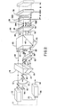
- Figure 2 depicts in schematic form a second embodiment of the instant invention where the optical beams are not in a single plane. This configuration permits a more compact optical system.
- the description of this figure is identical to Figure 1 and is numbered correspondingly. The only differences are that now the two beamsplitter/beam folder assemblies 16A and 16B illustrated in the embodiments of Figure 1 are replaced by a single beamsplitter/beam folder assembly 16 and the two half-wave retardation plates 29A and 29B illustrated in the embodiment of Figure 1 are replaced by a single half-wave retardation plate 29.
- light source 10 which, as previously mentioned, most preferably uses a laser, emits input beam 12 which is comprised of two linear orthogonally polarized components as indicated by the two arrows, which, again, may or may not be of the same optical frequency.
- source 10 provides an electrical reference signal 11 shown by dotted lines in Figure 2, corresponding to this frequency difference, with no such reference signal 11 being provided when the two linear orthogonally polarized components comprising input beam 12 are of the same optical frequency.
- Beam 12 is incident on the single beamsplitter/beam folder assembly 16.
- beamsplitter/beam folder assembly 16 is the same as for the beamsplitter/beam folder assembly 16A of Figure 1, namely to spatially separate the two frequency components in beam 12 using conventional polarization techniques.
- beam 12 is divided by beamsplitter/beam folder assembly 16, with the aid of antireflection coatings on the entrance and exit surfaces, polarizing coating 23 and surface 19 to become vertically polarized beam 30 and horizontally polarized beam 31.
- Beam 31 passes through the single half-wave retardation plate 29 which rotates the linear polarization of beam 31 by 90° so that resultant beam 33 has the same polarization as beam 30.
- Beams 30 and 33 enter polarizing beamsplitter 40 with polarizing coating 42 and are transmitted as beams 34 and 35 respectively.
- Beams 34 and 35 pass through quarter-wave retardation plate 44 and are converted into circularly polarized beams 50 and 51, respectively.
- Beam 51 is reflected from fixed reference mirror 71 to become beam 51A while beam 50 is reflected from movable mirror 70 affixed to the stage whose relative position is being measured to become 50A.
- Beams 50A and 51A pass back through quarter-wave retardation plate 44 and are converted back into linearly polarized beams that are orthogonally polarized to the original incident beams 34 and 35.
- Beams 50A and 51A are reflected by polarizing coating 42, retroreflector 45 and polarizing coating 42 a second time to become beams 56 and 57.
- Beams 56 and 57 pass through quarter-wave retardation plate 44 and are converted into circularly polarized beams 58 and 59.
- Beam 59 is reflected from fixed reference mirror 71 to become beam 59A while beam 58 is reflected from movable mirror 70 to become beam 58A.
- Beams 58A and 59A pass back through quarter-wave retardation plate 44 and are converted back into linearly polarized beams that are polarized the same as the original incident beams 34 and 35.
- Beams 58A and 59A are transmitted by polarized coating 42 and leave polarizing beamsplitter 40 as beams 60 and 63. Beams 60 and 63 are mutually parallel by virtue of the inherent optical properties of retroreflector 45, independent of any tilt that may be present between mirrors 70 and 71. Beam 60 passes through the single half-wave retardation plate 29 which rotates the linear polarization of beam 60 by 90° so that resultant beam 62 has a linear polarization which is orthogonal to beam 63.
- Beams 62 and 63 are combined by beamsplitter/beam folder assembly 16 in the same manner as accomplished by beamsplitter/beam folder assembly 16B of Figure 1, with the aid of antireflection coatings on the entrance and exit surfaces, polarizing coating 23 and surface 19 to become beam 80.
- beam 80 in the embodiment of Figure 2, like input beam 12, has two polarization components which are orthogonally polarized.
- Each polarization component as was true with the Figure 1 embodiment, has traversed exactly the same optical path length (through air and glass) except for the optical path, nd, between mirrors 70 and 71 where n is the index of refraction of the medium between mirrors 70 and 71 and d is the distance between mirrors 70 and 71.
- the optical path length corresponding to this distance, d results in a phase difference between the two polarization components of beam 80. Motion of mirror 70 causes this phase difference to vary.
- phase variation is directly proportional to the distance, D, moved by mirror 70 for a constant n and is measured by passing beam 80 through polarizer 81, oriented at 45° to each polarization component, which mixes the two orthogonally polarized components in beam 80 to give beam 82.
- polarizer 81 oriented at 45° to each polarization component, which mixes the two orthogonally polarized components in beam 80 to give beam 82.
- the phase variation is directly proportional to the change in n.
- the interference between the two frequency components is detected by photodetector 83 producing electrical signal 85.
- module 90 does not require reference signal 11 since there is no corresponding frequency difference, and it conventionally extracts the phase variation from signal 85 such as in the manner described in U.S. Patent No.
- electronic module 90 provides output 92 which, as previously mentioned with respect to the Figure 1 embodiment, is directly proportional to the change in optical path length, nd , between mirrors 70 and 71.
- output 92 which, as previously mentioned with respect to the Figure 1 embodiment, is directly proportional to the change in optical path length, nd , between mirrors 70 and 71.
- both the Figure 1 and 2 embodiments employ optical configurations which are extremely insensitive to measurement error because of changes in the other optical components, such as those induced mechanically or thermally, affect both polarization components equally and therefore have no influence on the measured phase variation 92.
- environmental effects such as variations in the refractive index of air, can be minimized by placing mirror 71 close to mirror 70 to reduce the optical pathlength difference between the two frequency components.
Landscapes
- Physics & Mathematics (AREA)
- General Physics & Mathematics (AREA)
- Instruments For Measurement Of Length By Optical Means (AREA)
Applications Claiming Priority (2)
| Application Number | Priority Date | Filing Date | Title |
|---|---|---|---|
| US87340686A | 1986-06-12 | 1986-06-12 | |
| US873406 | 1986-06-12 |
Publications (2)
| Publication Number | Publication Date |
|---|---|
| EP0249564A2 true EP0249564A2 (de) | 1987-12-16 |
| EP0249564A3 EP0249564A3 (de) | 1989-05-10 |
Family
ID=25361568
Family Applications (1)
| Application Number | Title | Priority Date | Filing Date |
|---|---|---|---|
| EP87401334A Withdrawn EP0249564A3 (de) | 1986-06-12 | 1987-06-12 | Differentialplanspiegelinterferometer mit Strahlteiler-/Strahlfaltungseinheit |
Country Status (3)
| Country | Link |
|---|---|
| EP (1) | EP0249564A3 (de) |
| JP (1) | JPS62298702A (de) |
| DE (1) | DE249564T1 (de) |
Cited By (1)
| Publication number | Priority date | Publication date | Assignee | Title |
|---|---|---|---|---|
| EP0359157A3 (de) * | 1988-09-12 | 1991-01-09 | Spindler & Hoyer GmbH & Co. | Symmetrische zweiarmige Einrichtung zum Messen von Längen mit einem Interferometer |
Family Cites Families (3)
| Publication number | Priority date | Publication date | Assignee | Title |
|---|---|---|---|---|
| US3656853A (en) * | 1966-11-07 | 1972-04-18 | Hewlett Packard Co | Interferometric system |
| US3788746A (en) * | 1972-10-02 | 1974-01-29 | Hewlett Packard Co | Optical dilatometer |
| US4711574A (en) * | 1984-04-27 | 1987-12-08 | Hewlett-Packard Company | Minimum deadpath interferometer and dilatometer |
-
1987
- 1987-06-03 JP JP62140730A patent/JPS62298702A/ja active Pending
- 1987-06-12 DE DE1987401334 patent/DE249564T1/de active Pending
- 1987-06-12 EP EP87401334A patent/EP0249564A3/de not_active Withdrawn
Cited By (1)
| Publication number | Priority date | Publication date | Assignee | Title |
|---|---|---|---|---|
| EP0359157A3 (de) * | 1988-09-12 | 1991-01-09 | Spindler & Hoyer GmbH & Co. | Symmetrische zweiarmige Einrichtung zum Messen von Längen mit einem Interferometer |
Also Published As
| Publication number | Publication date |
|---|---|
| EP0249564A3 (de) | 1989-05-10 |
| DE249564T1 (de) | 1988-08-11 |
| JPS62298702A (ja) | 1987-12-25 |
Similar Documents
| Publication | Publication Date | Title |
|---|---|---|
| US4802765A (en) | Differential plane mirror having beamsplitter/beam folder assembly | |
| US4693605A (en) | Differential plane mirror interferometer | |
| EP0227554B1 (de) | Differential-Interferometer mit flachem Spiegel | |
| EP0250306B1 (de) | Interferometer zur Winkelmessung | |
| US4859066A (en) | Linear and angular displacement measuring interferometer | |
| US4883357A (en) | Dual high stability interferometer | |
| US4881816A (en) | Linear and angular displacement measuring interferometer | |
| EP0281385B1 (de) | Planspiegelinterferometer | |
| US4685803A (en) | Method and apparatus for the measurement of the refractive index of a gas | |
| US3788746A (en) | Optical dilatometer | |
| US4881815A (en) | Linear and angular displacement measuring interferometer | |
| KR100322938B1 (ko) | 전자적인 주파수 체배수단을 사용하여 공기의 굴절률을 보상하는 방법 및 수퍼헤테로다인 간섭계 장치 | |
| US4802764A (en) | Differential plane mirror interferometer having beamsplitter/beam folder assembly | |
| US5187543A (en) | Differential displacement measuring interferometer | |
| EP0244275B1 (de) | Winkelmessinterferometer | |
| KR100941928B1 (ko) | 광위상 간섭측정법 및 그 시스템 | |
| US4950078A (en) | High accuracy differential plane mirror interferometer | |
| US4787747A (en) | Straightness of travel interferometer | |
| US4711574A (en) | Minimum deadpath interferometer and dilatometer | |
| US4930894A (en) | Minimum deadpath interferometer and dilatometer | |
| US5133599A (en) | High accuracy linear displacement interferometer with probe | |
| GB2261299A (en) | Optical interferometer | |
| EP0239506A2 (de) | Interferometer mit Differential Spiegelebene | |
| US4807997A (en) | Angular displacement measuring interferometer | |
| US5028137A (en) | Angular displacement measuring interferometer |
Legal Events
| Date | Code | Title | Description |
|---|---|---|---|
| PUAI | Public reference made under article 153(3) epc to a published international application that has entered the european phase |
Free format text: ORIGINAL CODE: 0009012 |
|
| AK | Designated contracting states |
Kind code of ref document: A2 Designated state(s): DE FR GB |
|
| EL | Fr: translation of claims filed | ||
| DET | De: translation of patent claims | ||
| PUAL | Search report despatched |
Free format text: ORIGINAL CODE: 0009013 |
|
| AK | Designated contracting states |
Kind code of ref document: A3 Designated state(s): DE FR GB |
|
| STAA | Information on the status of an ep patent application or granted ep patent |
Free format text: STATUS: THE APPLICATION IS DEEMED TO BE WITHDRAWN |
|
| 18D | Application deemed to be withdrawn |
Effective date: 19890701 |
|
| RIN1 | Information on inventor provided before grant (corrected) |
Inventor name: YOUNG, PETER S. Inventor name: SOMMARGREN, GARY E. |