EP0249444B1 - A corrosion, sound, and vibration-proofing method for metal structures - Google Patents
A corrosion, sound, and vibration-proofing method for metal structures Download PDFInfo
- Publication number
- EP0249444B1 EP0249444B1 EP87305094A EP87305094A EP0249444B1 EP 0249444 B1 EP0249444 B1 EP 0249444B1 EP 87305094 A EP87305094 A EP 87305094A EP 87305094 A EP87305094 A EP 87305094A EP 0249444 B1 EP0249444 B1 EP 0249444B1
- Authority
- EP
- European Patent Office
- Prior art keywords
- masking
- car body
- masking member
- underside
- coating
- Prior art date
- Legal status (The legal status is an assumption and is not a legal conclusion. Google has not performed a legal analysis and makes no representation as to the accuracy of the status listed.)
- Expired - Lifetime
Links
Images




Classifications
-
- B—PERFORMING OPERATIONS; TRANSPORTING
- B05—SPRAYING OR ATOMISING IN GENERAL; APPLYING FLUENT MATERIALS TO SURFACES, IN GENERAL
- B05C—APPARATUS FOR APPLYING FLUENT MATERIALS TO SURFACES, IN GENERAL
- B05C1/00—Apparatus in which liquid or other fluent material is applied to the surface of the work by contact with a member carrying the liquid or other fluent material, e.g. a porous member loaded with a liquid to be applied as a coating
-
- B—PERFORMING OPERATIONS; TRANSPORTING
- B05—SPRAYING OR ATOMISING IN GENERAL; APPLYING FLUENT MATERIALS TO SURFACES, IN GENERAL
- B05D—PROCESSES FOR APPLYING FLUENT MATERIALS TO SURFACES, IN GENERAL
- B05D1/00—Processes for applying liquids or other fluent materials
- B05D1/32—Processes for applying liquids or other fluent materials using means for protecting parts of a surface not to be coated, e.g. using stencils, resists
-
- B—PERFORMING OPERATIONS; TRANSPORTING
- B29—WORKING OF PLASTICS; WORKING OF SUBSTANCES IN A PLASTIC STATE IN GENERAL
- B29C—SHAPING OR JOINING OF PLASTICS; SHAPING OF MATERIAL IN A PLASTIC STATE, NOT OTHERWISE PROVIDED FOR; AFTER-TREATMENT OF THE SHAPED PRODUCTS, e.g. REPAIRING
- B29C59/00—Surface shaping of articles, e.g. embossing; Apparatus therefor
- B29C59/007—Forming single grooves or ribs, e.g. tear lines, weak spots
-
- C—CHEMISTRY; METALLURGY
- C23—COATING METALLIC MATERIAL; COATING MATERIAL WITH METALLIC MATERIAL; CHEMICAL SURFACE TREATMENT; DIFFUSION TREATMENT OF METALLIC MATERIAL; COATING BY VACUUM EVAPORATION, BY SPUTTERING, BY ION IMPLANTATION OR BY CHEMICAL VAPOUR DEPOSITION, IN GENERAL; INHIBITING CORROSION OF METALLIC MATERIAL OR INCRUSTATION IN GENERAL
- C23C—COATING METALLIC MATERIAL; COATING MATERIAL WITH METALLIC MATERIAL; SURFACE TREATMENT OF METALLIC MATERIAL BY DIFFUSION INTO THE SURFACE, BY CHEMICAL CONVERSION OR SUBSTITUTION; COATING BY VACUUM EVAPORATION, BY SPUTTERING, BY ION IMPLANTATION OR BY CHEMICAL VAPOUR DEPOSITION, IN GENERAL
- C23C4/00—Coating by spraying the coating material in the molten state, e.g. by flame, plasma or electric discharge
- C23C4/02—Pretreatment of the material to be coated, e.g. for coating on selected surface areas
-
- B—PERFORMING OPERATIONS; TRANSPORTING
- B29—WORKING OF PLASTICS; WORKING OF SUBSTANCES IN A PLASTIC STATE IN GENERAL
- B29K—INDEXING SCHEME ASSOCIATED WITH SUBCLASSES B29B, B29C OR B29D, RELATING TO MOULDING MATERIALS OR TO MATERIALS FOR MOULDS, REINFORCEMENTS, FILLERS OR PREFORMED PARTS, e.g. INSERTS
- B29K2105/00—Condition, form or state of moulded material or of the material to be shaped
- B29K2105/04—Condition, form or state of moulded material or of the material to be shaped cellular or porous
-
- Y—GENERAL TAGGING OF NEW TECHNOLOGICAL DEVELOPMENTS; GENERAL TAGGING OF CROSS-SECTIONAL TECHNOLOGIES SPANNING OVER SEVERAL SECTIONS OF THE IPC; TECHNICAL SUBJECTS COVERED BY FORMER USPC CROSS-REFERENCE ART COLLECTIONS [XRACs] AND DIGESTS
- Y10—TECHNICAL SUBJECTS COVERED BY FORMER USPC
- Y10T—TECHNICAL SUBJECTS COVERED BY FORMER US CLASSIFICATION
- Y10T428/00—Stock material or miscellaneous articles
- Y10T428/14—Layer or component removable to expose adhesive
- Y10T428/1424—Halogen containing compound
-
- Y—GENERAL TAGGING OF NEW TECHNOLOGICAL DEVELOPMENTS; GENERAL TAGGING OF CROSS-SECTIONAL TECHNOLOGIES SPANNING OVER SEVERAL SECTIONS OF THE IPC; TECHNICAL SUBJECTS COVERED BY FORMER USPC CROSS-REFERENCE ART COLLECTIONS [XRACs] AND DIGESTS
- Y10—TECHNICAL SUBJECTS COVERED BY FORMER USPC
- Y10T—TECHNICAL SUBJECTS COVERED BY FORMER US CLASSIFICATION
- Y10T428/00—Stock material or miscellaneous articles
- Y10T428/15—Sheet, web, or layer weakened to permit separation through thickness
-
- Y—GENERAL TAGGING OF NEW TECHNOLOGICAL DEVELOPMENTS; GENERAL TAGGING OF CROSS-SECTIONAL TECHNOLOGIES SPANNING OVER SEVERAL SECTIONS OF THE IPC; TECHNICAL SUBJECTS COVERED BY FORMER USPC CROSS-REFERENCE ART COLLECTIONS [XRACs] AND DIGESTS
- Y10—TECHNICAL SUBJECTS COVERED BY FORMER USPC
- Y10T—TECHNICAL SUBJECTS COVERED BY FORMER US CLASSIFICATION
- Y10T428/00—Stock material or miscellaneous articles
- Y10T428/249921—Web or sheet containing structurally defined element or component
- Y10T428/249953—Composite having voids in a component [e.g., porous, cellular, etc.]
- Y10T428/249976—Voids specified as closed
-
- Y—GENERAL TAGGING OF NEW TECHNOLOGICAL DEVELOPMENTS; GENERAL TAGGING OF CROSS-SECTIONAL TECHNOLOGIES SPANNING OVER SEVERAL SECTIONS OF THE IPC; TECHNICAL SUBJECTS COVERED BY FORMER USPC CROSS-REFERENCE ART COLLECTIONS [XRACs] AND DIGESTS
- Y10—TECHNICAL SUBJECTS COVERED BY FORMER USPC
- Y10T—TECHNICAL SUBJECTS COVERED BY FORMER US CLASSIFICATION
- Y10T428/00—Stock material or miscellaneous articles
- Y10T428/249921—Web or sheet containing structurally defined element or component
- Y10T428/249953—Composite having voids in a component [e.g., porous, cellular, etc.]
- Y10T428/249982—With component specified as adhesive or bonding agent
- Y10T428/249983—As outermost component
-
- Y—GENERAL TAGGING OF NEW TECHNOLOGICAL DEVELOPMENTS; GENERAL TAGGING OF CROSS-SECTIONAL TECHNOLOGIES SPANNING OVER SEVERAL SECTIONS OF THE IPC; TECHNICAL SUBJECTS COVERED BY FORMER USPC CROSS-REFERENCE ART COLLECTIONS [XRACs] AND DIGESTS
- Y10—TECHNICAL SUBJECTS COVERED BY FORMER USPC
- Y10T—TECHNICAL SUBJECTS COVERED BY FORMER US CLASSIFICATION
- Y10T428/00—Stock material or miscellaneous articles
- Y10T428/249921—Web or sheet containing structurally defined element or component
- Y10T428/249953—Composite having voids in a component [e.g., porous, cellular, etc.]
- Y10T428/249982—With component specified as adhesive or bonding agent
- Y10T428/249985—Composition of adhesive or bonding component specified
Definitions
- the present invention relates to a new corrosion, sound, and vibration-proofing method for metal structures such as for the underside of the floor of cars.
- Visco-elastic materials such as synthetic resin, rubber, asphalt are coated on the surface of a metal structure such as the underside of the floor of cars for the purpose of corrosion, sound, and vibration proofing.
- Said coating layer of visco-elastic materials covers the surface of said metal structure to protect said surface from flying stones; it seals the joined parts of the surface from water and corrosion.
- said coating layer absorbs sound from the outside and vibration of the surface of said metal structure to exhibit a sound and vibration-proofing effect. Accordingly, said coating layer must be thick for a remarkable sound and vibration-proofing effect and usually the desirable thickness of said coating layer may be 500 to 2000 ⁇ . Therefore, said thick coating layer obstructs the firm attachment of parts such as bolts, nuts, brackets, frames and the like to the surface of said metal structure.
- said metal structure usually has many holes for cables, operation wires and the like, and for drainage and the like.
- said visco-elastic material must be prevented from going into said holes when said visco-elastic material is coated on the surface of said metal structure.
- said visco-elastic material must be prevented from going into the holes that are in the outer panel which would give a bad appearance.
- adhesive tape has been used as a masking member to protect a part of a metal structure from the coating of said visco-elastic material. Namely, adhesive tape is attached to a part of a metal structure to protect it from said coating and, after the coating, said adhesive tape is removed from the part of said metal structure. Said part is not coated with said visco-elastic material since said part was covered with adhesive tape during surface treatment.
- Said adhesive tape as a masking member has faults.
- adhesive tape attached to the part to be protected is buried in the coating layer and it is very difficult to find said buried adhesive tape, and of course, it is very difficult to remove said buried adhesive tape.
- GB-A-1300178 discloses the idea of protecting an article, such as a small automobile part, during surface treatment such as by metal plating with a heat shrinkage resin foam which is subsequently removed by applying heat.
- a method of corrosion, sound, and vibration proofing the underside of a car body which comprises masking with masking members the parts of the surface of said car body underside which are intended not to be coated, coating a corrosion, sound and vibration proofing visco-elastic layer on said car body underside, and removing said masking members from said parts of said car body underside, characterised in that said masking members consist of a plastic foam.
- the invention provides a method of corrosion, sound and vibration proofing the underside of a car body with a visco-elastic layer by masking a plurality of parts of the surface of said car body underside which are not to be coated, applying the visco-elastic layer to a thickness of at least 500 microns to the underside of the car body and also to cover the masking applied to said plurality of parts and removing the masking characterised in that the masking consists of a plurality of discrete plastic foam masking members, in that said masking members are removed intact without shrinkage and in that the masking members are of polystyrene foam.
- panel-types may be used as the masking member, for the extending parts of said metal structures, block types with a slit may be used as the masking member, for protruding parts of said metal structures, tube types with hole may be used as the masking member, and for the holes in said metal structures, plug types may be used as the masking member.
- Figure 1 is a partial perspective view of a first embodiment of the present invention.
- Figure 2 is a partial side sectional view of the first embodiment of the present invention.
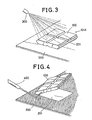
- Figure 3 is a partial perspective view of the first embodiment of the present invention in the case of coating.
- Figure 4 is a partial perspective view of the first embodiment of the present invention in the case of removing the masking member from the metal structure.
- Figure 5 is a partial perspective view of a second embodiment of the present invention.
- Figure 6 is a partial side sectional view of the second embodiment of the present invention.
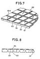
- Figure 7 is a partial perspective view of a third embodiment of the present invention.
- Figure 8 is a partial side sectional view of the third embodiment of the present invention.
- Figure 9 is a plane view of another embodiment of the release sheet having cutting lines.
- Figure 10 is a plane view of a further embodiment of the release sheet having cutting lines.
- Figure 11 is a cross-secitonal view of a fourth embodiment of the present invention.
- Figure 12 is a front view of the fourth embodiment of the present invention.
- Figure 13 is a partial perspective view of the fourth embodiment of the present invention in the case of masking.
- Figure 14 is a perspective view of a fifth embodiment of the present invention.
- Figure 15 is a partial perspective view of the fifth embodiment of the present invention in the case of masking.
- Figure 16 is a perspective view of a masking member having an open slit in the fifth embodiment of the present invention.
- Figure 17 is a side sectional view of a sixth embodiment of the present invention.
- Figure 18 is a front view of the sixth embodiment of the present invention.
- Figure 19 is a partial perspective view of the sixth embodiment of the present invention in the case of masking.
- Figure 20 is a perspective view of a seventh embodiment of the present invention.
- Figure 21 is a partial perspective view of the seventh embodiment of the instant invention.
- Figure 22 is a perspective view of an eighth embodiment of the present invention.
- Figure 23 is a cross-sectional view of the eighth embodiment of the present invention in the case of masking.
- Figure 24 is a perspective view of a masking member having a pull as part of the eighth embodiment of the present invention.
- Figure 25 is a perspective view of a car body of a practical example of the present invention.
- Figure 26 is a perspective view of Part A of the practical example.
- Figure 27 is a perspective view of Part B of the practical example.
- Figure 28 is a perspective view of Part C of the practical example.
- Figure 29 is a perspective view of Part D of the practical example.
- Figure 30 is a perspective view of Part E of the practical example.
- Figures 1 to 4 relate to the first embodiment of the present invention.
- a masking member (100) comprises a panel (101) consisting of a plastic foam, such as polystyrene foam, polyethylene foam, polypropylene foam, polymethacrylate foam and the like.
- Check-like grooves (102) are formed at regular intervals on both sides of said panel (101), and an adhesive layer (103) is formed on a side of said panel (101).
- Said adhesive layer (103) is covered with a release sheet (104) such as a polyethylene film, a polypropylene film, a release paper, and the like to prevent sticking to another article, the hands of workers, and the like when the masking members are handled; one placed upon another, transported, and the like.
- Said panel (101) of the masking member (100) may be produced by expansion molding, cutting out from blocks of a plastic foam and the grooves of the masking members of the present invention may include cutting lines. Said grooves may be formed when the panel is molded or by cutting after the panel is molded or cut out.
- Said panel may be colored by a suitable color for the purpose of selection of the specified masking member according to the part to be protected. Further, the colored masking member may be easily found when said masking member is removed after coating.
- the release sheet (104) is removed from the adhesive layer (103) and the panel (101) is torn long the grooves by hand into a piece (101A) having the proper size corresponding with a part (201) of metal structure (200) which is necessary to be protected from a coating of visco-elastic material.
- the resulting piece (101A) is then attached to said part (201) of said metal structure (200) by said adhesive layer (103) thereof as shown in Fig. 3.
- a liquid form of the visco-elestic material is sprayed from a spray gun (300) onto the surface of said metal structure (200).
- the part (201) of said metal structure (200) is not subjected to said coating since said part (201) is covered by piece (101A) of the masking member (100).
- said coated metal structure (200) is heated to dry it and/or cure it if desired.
- said piece (101A) is stripped off by a hook (400) as shown in Fig. 4 or by hand or in cases where the heating temperature is adequately higher than the softening point of the plastic of the material of said panel (101), said piece (101A) will shrink by said heating and come off by itself from said part (201) of said metal structure (200).
- the visco-elastic material used in the present invention may be plastic, rubber, asphalt, pitch and the like, and a solution, emulsion, dispersion, liquid prepolymer of said visco-elastic material or molten visco-elastic material may be used in the case of coating.
- Said liquid of the visco-elastic material may be such as polyvinyl chloride paste, polyvinyl chloride sol, an organic solution of polyacrylate, an organic solution of styrene-butadiene rubber, polyvinyl acetate emulsion, polyacrylate emulsion, styrene-butadiene rubber latex, an emulsion of ethylenevinyl acetate copolymer, polyurethane emulsion, asphalt emulsion, petroleum resin emulsion, polyethylene emulsion, molten ethylene-vinyl acetate copolymer, molten asphalt, molten petroleum resin, molten polyethylene, urethane prepolymer, unsaturated polyester resin and the like.
- Two or more kinds of said visco-elastic materials may be mixed together in the present invention.
- a dipping method may also be used for the coating of said visco-elastic materials.
- Figure 5 and Figure 6 relate to the second embodiment of the present invention.
- a masking member (110) comprises a panel (111) consisting of a plastic foam, the same as the first embodiment and grooves (112), the same as the first embodiment, are formed on both sides of said panel (111).
- a primer layer (115) is formed on a side of said panel (111) and an adhesive layer (113) is formed on said primer layer (115).
- Said adhesive layer (113) is covered with a release sheet (114), the same as the first embodiment.
- Said primer layer (115) prevents said adhesive layer (113) soaking into said panel (111) since said panel (111) consists of the plastic foam and the surface of said panel (111) is porous, and said primer layer (115) is formed by laminating the film of a plastic such as, polyethylene, polypropylene, vinylacetate-ethylene copolymer, polyvinylchloride and the like by heating or adhesive, or by coating with an emulsion or a solution of a synthetic resin such as acrylic resin, polyvinyl acetate resin, polyethylene, polypropylene, vinyl acetate-ethylene copolymer and the like on a side of said panel (111). Further, the skin layer formed on the surface of said panel (111), in cases where said panel (111) is produced by expansion molding, may also be used as said primer layer (115).
- a plastic such as, polyethylene, polypropylene, vinylacetate-ethylene copolymer, polyvinylchloride and the like by heating or adhesive, or by coating with an e
- Said panel may be colored by a suitable color for the purpose of selection of the specified masking member according to the part to be protected. Further, the colored masking member may be easily found when said masking member is removed after coating.
- Figure 7 to Figure 10 relate to the third embodiment of the present invention.
- a masking member (120) comprises a panel (121) consisting of a plastic foam, the same as the first and second embodiments and grooves (122), the same as the first and second embodiments, are formed on both sides of said panel (121).
- An adhesive layer (123) is formed on a side of said panel (121) and said adhesive layer (123) is covered with a release sheet (124).
- Cutting lines (124A) along the grooves (122) of said panel (121) are formed on said release sheet (124).
- Said panel may be colored by a suitable color for the purpose of selection of the specified masking member according to the part to be protected. Further, the colored masking member may be easily found when said masking member is removed after coating.
- said panel (121) is torn along said grooves (122) by hand into a piece (121A) having a size corresponding with a part of metal structure and, at the same time, said release sheet (124) is easily torn along said cutting lines (124A).
- Said cutting lines may include perforated lines (124B) as shown in Fig. 9 and discontinuous lines (124C) as shown in Fig. 10.
- Figure 11 to Figure 13 relate to the fourth embodiment of the present invention.
- a masking member (130) comprises a tube (131) consisting of a plastic foam, the same as the first, second and third embodiments and said masking member (130) has a blind hole (132).
- Said blind hole (132) has a tapering part (133) increasing, gradually in its diameter to the entrance of said hole (132).
- Said tube (131) may be colored by a suitable color for the purpose of selection of the specified masking member according to the part to be protected. Further, the colored masking member may be easily found when said masking member is removed after coating.
- Said masking member (130) is attached to a protruding part (211) of a metal structure (210) which is necessary to be protected from coating, by inserting said protruding part (211) into said blind hole (132) of said masking member (130) as shown in Fig. 14.
- said liquid of visco-elastic material is coated onto the surface of said metal structure (210).
- Said protruding part (211) of said metal structure (210) is not subjected to said coating since said protruding part (211) is covered with said masking member (130).
- said coated metal structure (210) is heated to dry it and/or cure it if desired.
- said masking member (130) is removed from said protruding part (211) by hand or in cases where the heating temperature is adequately higher than the softening point of the plastic of the material of said masking member (130), said masking member (130) will shrink by said heating and come off by itself from the said protruding part (211) of said metal structure (210). Further, said protruding part (211) is easily inserted into said hole (132) of said masking member (130) and said masking member (130) is firmly attached to said protruding part (211) by its elasticity since the said hole (132) of said masking member (130) has a tapering part (133) increasing gradually in its diameter to the entrance of said hole (132).
- Figure 14 to Figure 16 relate to the fifth embodiment of the present invention.
- a masking member (140) comprises a block (141) consisting of a plastic foam, the same as the first, second, third, and fourth embodiments and said block (141) has a blind slit (142).
- Said block (141) may be colored by a suitable color for the purpose of selection of the specified masking member according to the part to be protected. Further, the colored masking member may be easily found when said masking member is removed after coating.
- Said masking member (140) is attached to an extending part (221) of a metal structure (220) which is necessary to be protected from coating, by inserting said extending part (221) into said blind slit (142) of said masking member (140) as shown in Fig. 15.
- said block (141′) of said masking member (140′) may have an open slit (142′).
- Figure 17 to Figure 19 relate to the sixth embodiment of the present invention.
- a masking member (150) comprises a tube (151) consisting of a plastic foam, the same as the first, second, third, fourth and fifth embodiments, and said masking member (150) has an open hole (152).
- Said tube (151) may be colored by a suitable color for the purpose of selection of the specified masking member according to the part to be protected. Further, the colored masking member may be easily found when said masking member is removed after coating.
- Said masking member (150) is attached to a protruding part (231) of a metal structure (230) which is necessary to be protected from coating, by allowing said protruding part (231) to enter said open hole (152) of said masking member (150) as shown in Fig. 19.
- said liquid of the visco-elastic material is coated on the surface of said metal structure (230).
- Said protruding part (231) of said metal structure (230) is not subjected to said coating since said protruding part (231) is covered by said masking member (150).
- the center of said open hole (152) of said masking member (150) may have a smaller diameter than the both ends of said open hole (152). In this case, said masking member (150) is firmly attached to said protruding part (231) by its elasticity.
- Figure 20 and Figure 21 relate to the seventh embodiment of the present invention.
- a masking member (160) comprises a block (161) consisting of a plastic foam, the same as the first, second, third, fourth, fifth and sixth embodiments and said block (161) has a slit (162) both sides of which are opened.
- Said slit (162) has a tapering part (163) increasing gradually in its width to the entrance of said slit (162).
- Said block (161) may be colored by a suitable color for the purpose of selection of the specified masking member according to the part to be protected. Further, the colored masking member may be easily found when said masking member is removed after coating.
- Said masking member (160) is attached to a panel part (241) of a metal structure (240) which is necessary to be protected from coating, by inserting said panel part (241) into said slit (162) of said masking member (160) as shown in Fig. 21. Further, said panel part (241) of said metal structure (240) is easily inserted into said slit (162) of said masking member (160) and said masking member (160) is firmly attached to said panel part (241) by its elasticity.
- Figure 22 and Figure 23 relate to the eighth embodiment of the present invention.
- a masking member (170) has a plug-form comprising a head (171) and an inserting part (172) and said inserting part (172) has a tapering form increasing gradually in its diameter to said head (171).
- Said masking member (170) consists of a plastic foam, the same as the first, second, third, fourth, fifth, sixth and seventh embodiments, and said masking member (170) may be colored by a suitable color for the purpose of selection of the specified masking member according to the part to be protected. Further, the colored masking member may be easily found when said masking member is removed after coating.
- Said masking member (170) is attached to a hole (251) in a metal structure (250) by inserting the inserting part (172) of said masking member (170) into said hole (251) and the inside of said hole (251) is covered by said inserting part (172) of said masking member (170) and the circumference of said hole (251) is covered by said head (171) of said masking member (170) to protect the inside of said hole (251) and the circumference of said hole (251) from said coating.
- a grip (173) may be formed on the head (171) of said masking member (170).
- Coloring of said masking member may not always be necessary in the present invention.
- Figure 25 to Figure 30 show an applied embodiment in which the present invention is applied to the underside of the floor of cars.
- the masking members of the present invention are attached to parts A, B, C, D and E of the underside (261) of the floor of a car (260).
- said masking member (171) of Fig. 24 of the eighth embodiment may be attached to a hole (262) of part A into which a spring axis of a forward wheel is inserted and the circumference of the hole (262) is used as a bed for the spring. Therefore, the inside of the hole (262) is covered with the inserting part (172) of the masking member (170) and the circumference of the hole (262) is covered with the head (171) of the masking member (170) to protect these from the coating of visco-elastic material.
- the masking member (130) of the fourth embodiment is attached to a bolt (263) of part B which is used to attach a part to the underside (261) of the floor of a car (260).
- the masking member (170) of the eighth embodiment is inserted into a drainage hole (264), as shown in Figure 29, the masking member (140) of the fifth embodiment is attached to a bracket (265) of part D which is used to attach a part to the underside (261) of the floor of a car (260), and as shown in Figure 30, the masking member (100) of the first embodiment is attached to a screw hole (266) which is used to attach a part to the underside (261) of the floor of the car.
- said hole (262), said bolt (263), said drainage hole (264), said bracket (265) and said screw hole (266) are protected by said masking members of the present invention from the coating of visco-elastic material.
Landscapes
- Chemical & Material Sciences (AREA)
- Engineering & Computer Science (AREA)
- Mechanical Engineering (AREA)
- Materials Engineering (AREA)
- Plasma & Fusion (AREA)
- Chemical Kinetics & Catalysis (AREA)
- Physics & Mathematics (AREA)
- Metallurgy (AREA)
- Organic Chemistry (AREA)
- Details Or Accessories Of Spraying Plant Or Apparatus (AREA)
- Body Structure For Vehicles (AREA)
- Application Of Or Painting With Fluid Materials (AREA)
- Preventing Corrosion Or Incrustation Of Metals (AREA)
Description
- The present invention relates to a new corrosion, sound, and vibration-proofing method for metal structures such as for the underside of the floor of cars.
- Visco-elastic materials such as synthetic resin, rubber, asphalt are coated on the surface of a metal structure such as the underside of the floor of cars for the purpose of corrosion, sound, and vibration proofing. Said coating layer of visco-elastic materials covers the surface of said metal structure to protect said surface from flying stones; it seals the joined parts of the surface from water and corrosion.
- At the same time, said coating layer absorbs sound from the outside and vibration of the surface of said metal structure to exhibit a sound and vibration-proofing effect. Accordingly, said coating layer must be thick for a remarkable sound and vibration-proofing effect and usually the desirable thickness of said coating layer may be 500 to 2000 µ. Therefore, said thick coating layer obstructs the firm attachment of parts such as bolts, nuts, brackets, frames and the like to the surface of said metal structure.
- Further, said metal structure usually has many holes for cables, operation wires and the like, and for drainage and the like. In cases where said metal structure has holes, said visco-elastic material must be prevented from going into said holes when said visco-elastic material is coated on the surface of said metal structure. Especially in cars, said visco-elastic material must be prevented from going into the holes that are in the outer panel which would give a bad appearance.
- Therefore, it is necessary to protect such parts of said metal structure by masking members and then coat the surface of said metal structure with said visco-elastic material. After coating, said masking members may be removed from said surface of said metal structure.
- Hitherto, adhesive tape has been used as a masking member to protect a part of a metal structure from the coating of said visco-elastic material. Namely, adhesive tape is attached to a part of a metal structure to protect it from said coating and, after the coating, said adhesive tape is removed from the part of said metal structure. Said part is not coated with said visco-elastic material since said part was covered with adhesive tape during surface treatment.
- Said adhesive tape as a masking member has faults. In cases where the part to be protected from the coating is wide, it is troublesome to attach adhesive tape to the part to be protected and remove said adhesive tape from said part since a number of strips of adhesive tape must be attached to said part to cover the whole part, and further, in a case where the part to be protected from the coating is protruding, it is also troublesome to wind adhesive tape over and over again around the part to be protected and remove said adhesive tape from said part.
- Still further, adhesive tape attached to the part to be protected is buried in the coating layer and it is very difficult to find said buried adhesive tape, and of course, it is very difficult to remove said buried adhesive tape.
- Still further, it is very difficult to cover only the necessary parts of a metal structure by adhesive tape resulting in that parts which are not covered with the visco-elastic layer may remain.
- GB-A-1300178 discloses the idea of protecting an article, such as a small automobile part, during surface treatment such as by metal plating with a heat shrinkage resin foam which is subsequently removed by applying heat.
- According to the invention there is provided a method of corrosion, sound, and vibration proofing the underside of a car body which comprises masking with masking members the parts of the surface of said car body underside which are intended not to be coated, coating a corrosion, sound and vibration proofing visco-elastic layer on said car body underside, and removing said masking members from said parts of said car body underside, characterised in that said masking members consist of a plastic foam.
- In a particular form the invention provides a method of corrosion, sound and vibration proofing the underside of a car body with a visco-elastic layer by masking a plurality of parts of the surface of said car body underside which are not to be coated, applying the visco-elastic layer to a thickness of at least 500 microns to the underside of the car body and also to cover the masking applied to said plurality of parts and removing the masking characterised in that the masking consists of a plurality of discrete plastic foam masking members, in that said masking members are removed intact without shrinkage and in that the masking members are of polystyrene foam.
- For the even surfaces of said metal structures, panel-types may be used as the masking member, for the extending parts of said metal structures, block types with a slit may be used as the masking member, for protruding parts of said metal structures, tube types with hole may be used as the masking member, and for the holes in said metal structures, plug types may be used as the masking member.
- In order that the invention may be more easily understood the following description is given by way of example only with reference to the drawings in which:-
- Figure 1 is a partial perspective view of a first embodiment of the present invention.
- Figure 2 is a partial side sectional view of the first embodiment of the present invention.
- Figure 3 is a partial perspective view of the first embodiment of the present invention in the case of coating.
- Figure 4 is a partial perspective view of the first embodiment of the present invention in the case of removing the masking member from the metal structure.
- Figure 5 is a partial perspective view of a second embodiment of the present invention.
- Figure 6 is a partial side sectional view of the second embodiment of the present invention.
- Figure 7 is a partial perspective view of a third embodiment of the present invention.
- Figure 8 is a partial side sectional view of the third embodiment of the present invention.
- Figure 9 is a plane view of another embodiment of the release sheet having cutting lines.
- Figure 10 is a plane view of a further embodiment of the release sheet having cutting lines.
- Figure 11 is a cross-secitonal view of a fourth embodiment of the present invention.
- Figure 12 is a front view of the fourth embodiment of the present invention.
- Figure 13 is a partial perspective view of the fourth embodiment of the present invention in the case of masking.
- Figure 14 is a perspective view of a fifth embodiment of the present invention.
- Figure 15 is a partial perspective view of the fifth embodiment of the present invention in the case of masking.
- Figure 16 is a perspective view of a masking member having an open slit in the fifth embodiment of the present invention.
- Figure 17 is a side sectional view of a sixth embodiment of the present invention.
- Figure 18 is a front view of the sixth embodiment of the present invention.
- Figure 19 is a partial perspective view of the sixth embodiment of the present invention in the case of masking.
- Figure 20 is a perspective view of a seventh embodiment of the present invention.
- Figure 21 is a partial perspective view of the seventh embodiment of the instant invention.
- Figure 22 is a perspective view of an eighth embodiment of the present invention.
- Figure 23 is a cross-sectional view of the eighth embodiment of the present invention in the case of masking.
- Figure 24 is a perspective view of a masking member having a pull as part of the eighth embodiment of the present invention.
- Figure 25 is a perspective view of a car body of a practical example of the present invention.
- Figure 26 is a perspective view of Part A of the practical example.
- Figure 27 is a perspective view of Part B of the practical example.
- Figure 28 is a perspective view of Part C of the practical example.
- Figure 29 is a perspective view of Part D of the practical example.
- Figure 30 is a perspective view of Part E of the practical example.
- Figures 1 to 4 relate to the first embodiment of the present invention.
- Referring now to Figures 1 to 4, a masking member (100) comprises a panel (101) consisting of a plastic foam, such as polystyrene foam, polyethylene foam, polypropylene foam, polymethacrylate foam and the like. Check-like grooves (102) are formed at regular intervals on both sides of said panel (101), and an adhesive layer (103) is formed on a side of said panel (101). Said adhesive layer (103) is covered with a release sheet (104) such as a polyethylene film, a polypropylene film, a release paper, and the like to prevent sticking to another article, the hands of workers, and the like when the masking members are handled; one placed upon another, transported, and the like. Said panel (101) of the masking member (100) may be produced by expansion molding, cutting out from blocks of a plastic foam and the grooves of the masking members of the present invention may include cutting lines. Said grooves may be formed when the panel is molded or by cutting after the panel is molded or cut out.
- Said panel may be colored by a suitable color for the purpose of selection of the specified masking member according to the part to be protected. Further, the colored masking member may be easily found when said masking member is removed after coating.
- When the masking member (100) is used, the release sheet (104) is removed from the adhesive layer (103) and the panel (101) is torn long the grooves by hand into a piece (101A) having the proper size corresponding with a part (201) of metal structure (200) which is necessary to be protected from a coating of visco-elastic material. The resulting piece (101A) is then attached to said part (201) of said metal structure (200) by said adhesive layer (103) thereof as shown in Fig. 3.
- In the case of coating, a liquid form of the visco-elestic material is sprayed from a spray gun (300) onto the surface of said metal structure (200). The part (201) of said metal structure (200) is not subjected to said coating since said part (201) is covered by piece (101A) of the masking member (100). After coating, said coated metal structure (200) is heated to dry it and/or cure it if desired. After or before said heating, said piece (101A) is stripped off by a hook (400) as shown in Fig. 4 or by hand or in cases where the heating temperature is adequately higher than the softening point of the plastic of the material of said panel (101), said piece (101A) will shrink by said heating and come off by itself from said part (201) of said metal structure (200).
- The visco-elastic material used in the present invention may be plastic, rubber, asphalt, pitch and the like, and a solution, emulsion, dispersion, liquid prepolymer of said visco-elastic material or molten visco-elastic material may be used in the case of coating. Said liquid of the visco-elastic material may be such as polyvinyl chloride paste, polyvinyl chloride sol, an organic solution of polyacrylate, an organic solution of styrene-butadiene rubber, polyvinyl acetate emulsion, polyacrylate emulsion, styrene-butadiene rubber latex, an emulsion of ethylenevinyl acetate copolymer, polyurethane emulsion, asphalt emulsion, petroleum resin emulsion, polyethylene emulsion, molten ethylene-vinyl acetate copolymer, molten asphalt, molten petroleum resin, molten polyethylene, urethane prepolymer, unsaturated polyester resin and the like. Two or more kinds of said visco-elastic materials may be mixed together in the present invention.
- A dipping method may also be used for the coating of said visco-elastic materials.
- Figure 5 and Figure 6 relate to the second embodiment of the present invention.
- Referring now to Fig. 5 and Fig. 6, a masking member (110) comprises a panel (111) consisting of a plastic foam, the same as the first embodiment and grooves (112), the same as the first embodiment, are formed on both sides of said panel (111). A primer layer (115) is formed on a side of said panel (111) and an adhesive layer (113) is formed on said primer layer (115). Said adhesive layer (113) is covered with a release sheet (114), the same as the first embodiment. Said primer layer (115) prevents said adhesive layer (113) soaking into said panel (111) since said panel (111) consists of the plastic foam and the surface of said panel (111) is porous, and said primer layer (115) is formed by laminating the film of a plastic such as, polyethylene, polypropylene, vinylacetate-ethylene copolymer, polyvinylchloride and the like by heating or adhesive, or by coating with an emulsion or a solution of a synthetic resin such as acrylic resin, polyvinyl acetate resin, polyethylene, polypropylene, vinyl acetate-ethylene copolymer and the like on a side of said panel (111). Further, the skin layer formed on the surface of said panel (111), in cases where said panel (111) is produced by expansion molding, may also be used as said primer layer (115).
- Said panel may be colored by a suitable color for the purpose of selection of the specified masking member according to the part to be protected. Further, the colored masking member may be easily found when said masking member is removed after coating.
- Figure 7 to Figure 10 relate to the third embodiment of the present invention.
- Referring now to Fig. 7 and Fig. 8, a masking member (120) comprises a panel (121) consisting of a plastic foam, the same as the first and second embodiments and grooves (122), the same as the first and second embodiments, are formed on both sides of said panel (121). An adhesive layer (123) is formed on a side of said panel (121) and said adhesive layer (123) is covered with a release sheet (124). Cutting lines (124A) along the grooves (122) of said panel (121) are formed on said release sheet (124).
- Said panel may be colored by a suitable color for the purpose of selection of the specified masking member according to the part to be protected. Further, the colored masking member may be easily found when said masking member is removed after coating.
- When said masking member (120) is used, said panel (121) is torn along said grooves (122) by hand into a piece (121A) having a size corresponding with a part of metal structure and, at the same time, said release sheet (124) is easily torn along said cutting lines (124A). Said cutting lines may include perforated lines (124B) as shown in Fig. 9 and discontinuous lines (124C) as shown in Fig. 10.
- Figure 11 to Figure 13 relate to the fourth embodiment of the present invention.
- Referring now to Fig. 11 and Fig. 12, a masking member (130) comprises a tube (131) consisting of a plastic foam, the same as the first, second and third embodiments and said masking member (130) has a blind hole (132). Said blind hole (132) has a tapering part (133) increasing, gradually in its diameter to the entrance of said hole (132).
- Said tube (131) may be colored by a suitable color for the purpose of selection of the specified masking member according to the part to be protected. Further, the colored masking member may be easily found when said masking member is removed after coating.
- Said masking member (130) is attached to a protruding part (211) of a metal structure (210) which is necessary to be protected from coating, by inserting said protruding part (211) into said blind hole (132) of said masking member (130) as shown in Fig. 14. After said masking member (130) is attached to said protruding part (211), said liquid of visco-elastic material is coated onto the surface of said metal structure (210). Said protruding part (211) of said metal structure (210) is not subjected to said coating since said protruding part (211) is covered with said masking member (130). After coating, said coated metal structure (210) is heated to dry it and/or cure it if desired. After or before said heating, said masking member (130) is removed from said protruding part (211) by hand or in cases where the heating temperature is adequately higher than the softening point of the plastic of the material of said masking member (130), said masking member (130) will shrink by said heating and come off by itself from the said protruding part (211) of said metal structure (210). Further, said protruding part (211) is easily inserted into said hole (132) of said masking member (130) and said masking member (130) is firmly attached to said protruding part (211) by its elasticity since the said hole (132) of said masking member (130) has a tapering part (133) increasing gradually in its diameter to the entrance of said hole (132).
- Figure 14 to Figure 16 relate to the fifth embodiment of the present invention.
- Referring now to Fig. 14 and Fig. 15, a masking member (140) comprises a block (141) consisting of a plastic foam, the same as the first, second, third, and fourth embodiments and said block (141) has a blind slit (142).
- Said block (141) may be colored by a suitable color for the purpose of selection of the specified masking member according to the part to be protected. Further, the colored masking member may be easily found when said masking member is removed after coating.
- Said masking member (140) is attached to an extending part (221) of a metal structure (220) which is necessary to be protected from coating, by inserting said extending part (221) into said blind slit (142) of said masking member (140) as shown in Fig. 15.
- As shown in Fig. 16, said block (141′) of said masking member (140′) may have an open slit (142′).
- Figure 17 to Figure 19 relate to the sixth embodiment of the present invention.
- Referring now to Fig. 17 to Fig. 19, a masking member (150) comprises a tube (151) consisting of a plastic foam, the same as the first, second, third, fourth and fifth embodiments, and said masking member (150) has an open hole (152).
- Said tube (151) may be colored by a suitable color for the purpose of selection of the specified masking member according to the part to be protected. Further, the colored masking member may be easily found when said masking member is removed after coating.
- Said masking member (150) is attached to a protruding part (231) of a metal structure (230) which is necessary to be protected from coating, by allowing said protruding part (231) to enter said open hole (152) of said masking member (150) as shown in Fig. 19. After said masking member (150) is attached to said protruding part (231), said liquid of the visco-elastic material is coated on the surface of said metal structure (230). Said protruding part (231) of said metal structure (230) is not subjected to said coating since said protruding part (231) is covered by said masking member (150). The center of said open hole (152) of said masking member (150) may have a smaller diameter than the both ends of said open hole (152). In this case, said masking member (150) is firmly attached to said protruding part (231) by its elasticity.
- Figure 20 and Figure 21 relate to the seventh embodiment of the present invention.
- Referring now to Fig. 20 and Fig. 21, a masking member (160) comprises a block (161) consisting of a plastic foam, the same as the first, second, third, fourth, fifth and sixth embodiments and said block (161) has a slit (162) both sides of which are opened. Said slit (162) has a tapering part (163) increasing gradually in its width to the entrance of said slit (162).
- Said block (161) may be colored by a suitable color for the purpose of selection of the specified masking member according to the part to be protected. Further, the colored masking member may be easily found when said masking member is removed after coating.
- Said masking member (160) is attached to a panel part (241) of a metal structure (240) which is necessary to be protected from coating, by inserting said panel part (241) into said slit (162) of said masking member (160) as shown in Fig. 21. Further, said panel part (241) of said metal structure (240) is easily inserted into said slit (162) of said masking member (160) and said masking member (160) is firmly attached to said panel part (241) by its elasticity.
- Figure 22 and Figure 23 relate to the eighth embodiment of the present invention.
- Referring now to Fig. 22 and Fig. 23, a masking member (170) has a plug-form comprising a head (171) and an inserting part (172) and said inserting part (172) has a tapering form increasing gradually in its diameter to said head (171). Said masking member (170) consists of a plastic foam, the same as the first, second, third, fourth, fifth, sixth and seventh embodiments, and said masking member (170) may be colored by a suitable color for the purpose of selection of the specified masking member according to the part to be protected. Further, the colored masking member may be easily found when said masking member is removed after coating.
- Said masking member (170) is attached to a hole (251) in a metal structure (250) by inserting the inserting part (172) of said masking member (170) into said hole (251) and the inside of said hole (251) is covered by said inserting part (172) of said masking member (170) and the circumference of said hole (251) is covered by said head (171) of said masking member (170) to protect the inside of said hole (251) and the circumference of said hole (251) from said coating. It may be very easy to insert said masking member (170) into said hole (251) since the inserting part of said masking member (170) has a tapering form increasing gradually in its diameter to said head (171) and said masking member (170) may be firmly attached to said hole (251) by its elasticity.
- As shown in Figure 24, a grip (173) may be formed on the head (171) of said masking member (170).
- Coloring of said masking member may not always be necessary in the present invention.
- Figure 25 to Figure 30 show an applied embodiment in which the present invention is applied to the underside of the floor of cars. As shown in Fig. 25, the masking members of the present invention are attached to parts A, B, C, D and E of the underside (261) of the floor of a car (260).
- Namely, as shown in Fig. 26 said masking member (171) of Fig. 24 of the eighth embodiment may be attached to a hole (262) of part A into which a spring axis of a forward wheel is inserted and the circumference of the hole (262) is used as a bed for the spring. Therefore, the inside of the hole (262) is covered with the inserting part (172) of the masking member (170) and the circumference of the hole (262) is covered with the head (171) of the masking member (170) to protect these from the coating of visco-elastic material.
- As shown in Fig. 27, the masking member (130) of the fourth embodiment is attached to a bolt (263) of part B which is used to attach a part to the underside (261) of the floor of a car (260).
- As shown in Figure 28, the masking member (170) of the eighth embodiment is inserted into a drainage hole (264), as shown in Figure 29, the masking member (140) of the fifth embodiment is attached to a bracket (265) of part D which is used to attach a part to the underside (261) of the floor of a car (260), and as shown in Figure 30, the masking member (100) of the first embodiment is attached to a screw hole (266) which is used to attach a part to the underside (261) of the floor of the car.
- Thus, said hole (262), said bolt (263), said drainage hole (264), said bracket (265) and said screw hole (266) are protected by said masking members of the present invention from the coating of visco-elastic material.
Claims (11)
Applications Claiming Priority (2)
| Application Number | Priority Date | Filing Date | Title |
|---|---|---|---|
| JP132959/86 | 1986-06-09 | ||
| JP61132959A JP2514173B2 (en) | 1986-06-09 | 1986-06-09 | Anti-corrosion, anti-noise and anti-vibration treatment method for under floor of automobile |
Publications (3)
| Publication Number | Publication Date |
|---|---|
| EP0249444A2 EP0249444A2 (en) | 1987-12-16 |
| EP0249444A3 EP0249444A3 (en) | 1988-09-28 |
| EP0249444B1 true EP0249444B1 (en) | 1991-09-25 |
Family
ID=15093498
Family Applications (1)
| Application Number | Title | Priority Date | Filing Date |
|---|---|---|---|
| EP87305094A Expired - Lifetime EP0249444B1 (en) | 1986-06-09 | 1987-06-09 | A corrosion, sound, and vibration-proofing method for metal structures |
Country Status (7)
| Country | Link |
|---|---|
| US (1) | US4913786A (en) |
| EP (1) | EP0249444B1 (en) |
| JP (1) | JP2514173B2 (en) |
| KR (1) | KR940004121B1 (en) |
| CA (1) | CA1280648C (en) |
| DE (1) | DE3773268D1 (en) |
| SG (1) | SG33993G (en) |
Cited By (11)
| Publication number | Priority date | Publication date | Assignee | Title |
|---|---|---|---|---|
| EP0368615A1 (en) * | 1988-11-07 | 1990-05-16 | Nagoya Oilchemical Co., Ltd. | Masking member |
| EP0370796A1 (en) * | 1988-11-23 | 1990-05-30 | Nagoya Oilchemical Co., Ltd. | A corrosion, sound, and vibration-proofing method for metal structures |
| EP0384696A1 (en) * | 1989-02-22 | 1990-08-29 | Nagoya Oilchemical Co., Ltd. | Masking member |
| EP0384695A1 (en) * | 1989-02-22 | 1990-08-29 | Nagoya Oilchemical Co., Ltd. | Masking member |
| AU623720B2 (en) * | 1989-12-22 | 1992-05-21 | Nagoya Oilchemical Co., Ltd. | A method of corrosion, sound, and vibration proofing of a metal structure |
| GB2254811A (en) * | 1991-04-19 | 1992-10-21 | Minnesota Mining & Mfg | Masking using a foam web |
| US5260097A (en) * | 1988-09-22 | 1993-11-09 | Jean Silvestre | Method for masking a surface by adhesive application of an elongated, compressible, windowless cushion |
| US5266375A (en) * | 1989-11-22 | 1993-11-30 | Nagoya Oilchemical Co., Ltd. | Masking member |
| US5547725A (en) * | 1994-02-25 | 1996-08-20 | Tesa Tape Inc. | Production of a novel sculptured strip of plastic foam |
| EP0884235A2 (en) | 1997-06-11 | 1998-12-16 | Volkswagen Aktiengesellschaft | Arrangement for mounting a cable lead-through plug in a coated metal sheet, and masking member |
| US5885395A (en) * | 1995-02-28 | 1999-03-23 | Western; Donald Murray | Masking method and device |
Families Citing this family (14)
| Publication number | Priority date | Publication date | Assignee | Title |
|---|---|---|---|---|
| US5328723A (en) * | 1986-09-30 | 1994-07-12 | Nagoya Oilchemical Co., Ltd. | Masking member |
| JPH01123387U (en) * | 1988-02-18 | 1989-08-22 | ||
| JPH01151866U (en) * | 1988-03-25 | 1989-10-19 | ||
| US6793998B1 (en) | 1988-09-22 | 2004-09-21 | Jean Silvestre | Masking method and masking means |
| CA2017893A1 (en) * | 1989-06-02 | 1990-12-02 | Seinosuke Horiki | Method for a surface treatment |
| JPH033479U (en) * | 1989-06-02 | 1991-01-14 | ||
| US5061428A (en) * | 1990-01-04 | 1991-10-29 | Davidson Textron Inc. | Method for plastic coating foam molding insert |
| JPH0570666U (en) * | 1992-02-28 | 1993-09-24 | 名古屋油化株式会社 | Masking material |
| JP2004016902A (en) * | 2002-06-14 | 2004-01-22 | Nagoya Oil Chem Co Ltd | Masking material |
| US9179814B2 (en) * | 2012-04-13 | 2015-11-10 | The Procter & Gamble Company | Cleaning article comprising lines of frangibility with marked indicia |
| USD679063S1 (en) | 2012-04-13 | 2013-03-26 | The Procter & Gamble Company | Foam cleaning implement |
| US9518317B2 (en) * | 2012-05-11 | 2016-12-13 | General Electric Company | Method of coating a component, method of forming cooling holes and a water soluble aperture plug |
| DE102012213442A1 (en) * | 2012-07-31 | 2014-02-27 | Zf Friedrichshafen Ag | base element |
| CN106269398A (en) * | 2015-05-29 | 2017-01-04 | 江苏银环新能源科技有限公司 | Double glass solar opto-electronic boards hook automatic gluing machine |
Family Cites Families (10)
| Publication number | Priority date | Publication date | Assignee | Title |
|---|---|---|---|---|
| US3667988A (en) * | 1969-07-09 | 1972-06-06 | Nagoya Yukagaku Kogyo Kk | Masking in surface treatment of articles |
| DE2112731B1 (en) * | 1971-03-17 | 1972-10-12 | Helmut Frielingsdorf | Template for repainting motor vehicles |
| JPS507499B2 (en) * | 1971-08-06 | 1975-03-26 | ||
| FR2384683A1 (en) * | 1977-03-22 | 1978-10-20 | Dourdin | Temporary cover plate for apertures in machine components - comprises heat-shrinkable polystyrene plate detachably glued to rim of the opening |
| DE2852828C2 (en) * | 1978-12-07 | 1981-02-26 | Teroson Gmbh, 6900 Heidelberg | Process for the production of a structure-borne sound-absorbing coating |
| JPS5737386A (en) * | 1980-08-15 | 1982-03-01 | Sony Corp | Manufacture of hologram |
| JPS58119381A (en) * | 1982-01-08 | 1983-07-15 | Mitui Toatsu Chem Inc | Method for coating under body of automobile |
| JPS6087879A (en) * | 1983-10-18 | 1985-05-17 | Sunstar Giken Kk | Sound and vibration insulating treatment of car body |
| CA1296179C (en) * | 1985-06-27 | 1992-02-25 | Toyota Jidosha Kabushiki Kaisha | Masking member |
| JPH0320115Y2 (en) * | 1986-06-03 | 1991-04-30 |
-
1986
- 1986-06-09 JP JP61132959A patent/JP2514173B2/en not_active Expired - Fee Related
-
1987
- 1987-06-05 KR KR1019870005751A patent/KR940004121B1/en not_active Expired - Fee Related
- 1987-06-08 CA CA000539080A patent/CA1280648C/en not_active Expired - Lifetime
- 1987-06-09 EP EP87305094A patent/EP0249444B1/en not_active Expired - Lifetime
- 1987-06-09 DE DE8787305094T patent/DE3773268D1/en not_active Expired - Lifetime
-
1988
- 1988-11-23 US US07/276,407 patent/US4913786A/en not_active Expired - Lifetime
-
1993
- 1993-03-26 SG SG339/93A patent/SG33993G/en unknown
Cited By (12)
| Publication number | Priority date | Publication date | Assignee | Title |
|---|---|---|---|---|
| US5260097A (en) * | 1988-09-22 | 1993-11-09 | Jean Silvestre | Method for masking a surface by adhesive application of an elongated, compressible, windowless cushion |
| EP0368615A1 (en) * | 1988-11-07 | 1990-05-16 | Nagoya Oilchemical Co., Ltd. | Masking member |
| EP0370796A1 (en) * | 1988-11-23 | 1990-05-30 | Nagoya Oilchemical Co., Ltd. | A corrosion, sound, and vibration-proofing method for metal structures |
| EP0384696A1 (en) * | 1989-02-22 | 1990-08-29 | Nagoya Oilchemical Co., Ltd. | Masking member |
| EP0384695A1 (en) * | 1989-02-22 | 1990-08-29 | Nagoya Oilchemical Co., Ltd. | Masking member |
| US5266375A (en) * | 1989-11-22 | 1993-11-30 | Nagoya Oilchemical Co., Ltd. | Masking member |
| AU623720B2 (en) * | 1989-12-22 | 1992-05-21 | Nagoya Oilchemical Co., Ltd. | A method of corrosion, sound, and vibration proofing of a metal structure |
| GB2254811A (en) * | 1991-04-19 | 1992-10-21 | Minnesota Mining & Mfg | Masking using a foam web |
| GB2254811B (en) * | 1991-04-19 | 1994-11-30 | Minnesota Mining & Mfg | Masking methods using a foam web |
| US5547725A (en) * | 1994-02-25 | 1996-08-20 | Tesa Tape Inc. | Production of a novel sculptured strip of plastic foam |
| US5885395A (en) * | 1995-02-28 | 1999-03-23 | Western; Donald Murray | Masking method and device |
| EP0884235A2 (en) | 1997-06-11 | 1998-12-16 | Volkswagen Aktiengesellschaft | Arrangement for mounting a cable lead-through plug in a coated metal sheet, and masking member |
Also Published As
| Publication number | Publication date |
|---|---|
| EP0249444A2 (en) | 1987-12-16 |
| US4913786A (en) | 1990-04-03 |
| KR940004121B1 (en) | 1994-05-13 |
| EP0249444A3 (en) | 1988-09-28 |
| KR880000149A (en) | 1988-03-23 |
| SG33993G (en) | 1993-05-21 |
| CA1280648C (en) | 1991-02-26 |
| JP2514173B2 (en) | 1996-07-10 |
| DE3773268D1 (en) | 1991-10-31 |
| JPS62289276A (en) | 1987-12-16 |
Similar Documents
| Publication | Publication Date | Title |
|---|---|---|
| EP0249444A2 (en) | A corrosion, sound, and vibration-proofing method for metal structures | |
| EP0368615B1 (en) | Masking member | |
| EP0262946B1 (en) | A masking member | |
| KR930005803Y1 (en) | Expanding and shrinking member | |
| EP0207720B1 (en) | A masking member | |
| US6025045A (en) | Edge trimming tape and method of manufacture | |
| US4358482A (en) | End finishing composite trim strips | |
| EP0249508B1 (en) | A masking member | |
| CA1300437C (en) | Corrosion, sound, and vibration-proof method for metal structure | |
| US20040166298A1 (en) | Plastic masking cover | |
| EP0370796A1 (en) | A corrosion, sound, and vibration-proofing method for metal structures | |
| US5413637A (en) | Masking methods using a foam web | |
| AU623720B2 (en) | A method of corrosion, sound, and vibration proofing of a metal structure | |
| JP2566204B2 (en) | Anti-corrosion and anti-vibration treatment method for metal structures | |
| EP0580804B1 (en) | Masking methods using a foam web | |
| JP2612241B2 (en) | Corrosion and vibration control of metal structures | |
| WO1998055297A1 (en) | Plastic masking cover | |
| EP1799358A1 (en) | Embossed masking sheet with pressure sensitive adhesive regions | |
| JPH03221173A (en) | Anticorrosion, soundproofing and damping treatment of metal structure | |
| GB2281871A (en) | Masking device | |
| JPH0337739Y2 (en) | ||
| EP0528803A1 (en) | Method of masking | |
| JPH0256152B2 (en) | ||
| JPS6125656A (en) | Tape for coating | |
| JPS60251967A (en) | Two-color painting method |
Legal Events
| Date | Code | Title | Description |
|---|---|---|---|
| PUAI | Public reference made under article 153(3) epc to a published international application that has entered the european phase |
Free format text: ORIGINAL CODE: 0009012 |
|
| AK | Designated contracting states |
Kind code of ref document: A2 Designated state(s): DE FR GB IT SE |
|
| PUAL | Search report despatched |
Free format text: ORIGINAL CODE: 0009013 |
|
| AK | Designated contracting states |
Kind code of ref document: A3 Designated state(s): DE FR GB IT SE |
|
| 17P | Request for examination filed |
Effective date: 19881230 |
|
| 17Q | First examination report despatched |
Effective date: 19900330 |
|
| GRAA | (expected) grant |
Free format text: ORIGINAL CODE: 0009210 |
|
| AK | Designated contracting states |
Kind code of ref document: B1 Designated state(s): DE FR GB IT SE |
|
| ITF | It: translation for a ep patent filed | ||
| ET | Fr: translation filed | ||
| REF | Corresponds to: |
Ref document number: 3773268 Country of ref document: DE Date of ref document: 19911031 |
|
| REG | Reference to a national code |
Ref country code: GB Ref legal event code: 732 |
|
| PLBE | No opposition filed within time limit |
Free format text: ORIGINAL CODE: 0009261 |
|
| STAA | Information on the status of an ep patent application or granted ep patent |
Free format text: STATUS: NO OPPOSITION FILED WITHIN TIME LIMIT |
|
| 26N | No opposition filed | ||
| REG | Reference to a national code |
Ref country code: FR Ref legal event code: CL |
|
| EAL | Se: european patent in force in sweden |
Ref document number: 87305094.2 |
|
| PGFP | Annual fee paid to national office [announced via postgrant information from national office to epo] |
Ref country code: SE Payment date: 19980616 Year of fee payment: 12 |
|
| PG25 | Lapsed in a contracting state [announced via postgrant information from national office to epo] |
Ref country code: SE Free format text: THE PATENT HAS BEEN ANNULLED BY A DECISION OF A NATIONAL AUTHORITY Effective date: 19990629 |
|
| REG | Reference to a national code |
Ref country code: GB Ref legal event code: 732E |
|
| EUG | Se: european patent has lapsed |
Ref document number: 87305094.2 |
|
| REG | Reference to a national code |
Ref country code: GB Ref legal event code: IF02 |
|
| PGFP | Annual fee paid to national office [announced via postgrant information from national office to epo] |
Ref country code: DE Payment date: 20050602 Year of fee payment: 19 |
|
| PGFP | Annual fee paid to national office [announced via postgrant information from national office to epo] |
Ref country code: GB Payment date: 20050608 Year of fee payment: 19 Ref country code: FR Payment date: 20050608 Year of fee payment: 19 |
|
| PG25 | Lapsed in a contracting state [announced via postgrant information from national office to epo] |
Ref country code: GB Free format text: LAPSE BECAUSE OF NON-PAYMENT OF DUE FEES Effective date: 20060609 |
|
| PGFP | Annual fee paid to national office [announced via postgrant information from national office to epo] |
Ref country code: IT Payment date: 20060630 Year of fee payment: 20 |
|
| PG25 | Lapsed in a contracting state [announced via postgrant information from national office to epo] |
Ref country code: DE Free format text: LAPSE BECAUSE OF NON-PAYMENT OF DUE FEES Effective date: 20070103 |
|
| GBPC | Gb: european patent ceased through non-payment of renewal fee |
Effective date: 20060609 |
|
| REG | Reference to a national code |
Ref country code: FR Ref legal event code: ST Effective date: 20070228 |
|
| PG25 | Lapsed in a contracting state [announced via postgrant information from national office to epo] |
Ref country code: FR Free format text: LAPSE BECAUSE OF NON-PAYMENT OF DUE FEES Effective date: 20060630 |