EP0249393A2 - Eléments pour une chambre de combustion d'une fusée - Google Patents
Eléments pour une chambre de combustion d'une fusée Download PDFInfo
- Publication number
- EP0249393A2 EP0249393A2 EP87304932A EP87304932A EP0249393A2 EP 0249393 A2 EP0249393 A2 EP 0249393A2 EP 87304932 A EP87304932 A EP 87304932A EP 87304932 A EP87304932 A EP 87304932A EP 0249393 A2 EP0249393 A2 EP 0249393A2
- Authority
- EP
- European Patent Office
- Prior art keywords
- carbon
- insert
- component
- silicon carbide
- insert component
- Prior art date
- Legal status (The legal status is an assumption and is not a legal conclusion. Google has not performed a legal analysis and makes no representation as to the accuracy of the status listed.)
- Withdrawn
Links
Images

Classifications
-
- F—MECHANICAL ENGINEERING; LIGHTING; HEATING; WEAPONS; BLASTING
- F02—COMBUSTION ENGINES; HOT-GAS OR COMBUSTION-PRODUCT ENGINE PLANTS
- F02K—JET-PROPULSION PLANTS
- F02K9/00—Rocket-engine plants, i.e. plants carrying both fuel and oxidant therefor; Control thereof
- F02K9/42—Rocket-engine plants, i.e. plants carrying both fuel and oxidant therefor; Control thereof using liquid or gaseous propellants
- F02K9/60—Constructional parts; Details not otherwise provided for
- F02K9/62—Combustion or thrust chambers
- F02K9/64—Combustion or thrust chambers having cooling arrangements
-
- F—MECHANICAL ENGINEERING; LIGHTING; HEATING; WEAPONS; BLASTING
- F02—COMBUSTION ENGINES; HOT-GAS OR COMBUSTION-PRODUCT ENGINE PLANTS
- F02K—JET-PROPULSION PLANTS
- F02K9/00—Rocket-engine plants, i.e. plants carrying both fuel and oxidant therefor; Control thereof
- F02K9/42—Rocket-engine plants, i.e. plants carrying both fuel and oxidant therefor; Control thereof using liquid or gaseous propellants
- F02K9/60—Constructional parts; Details not otherwise provided for
- F02K9/62—Combustion or thrust chambers
Definitions
- Rocket engines especially ablatively cooled liquid propellant rocket engines, are presently used in a number of important tactical and strategic applications and offer both simplicity of design and high reliability.
- One major problem that is encountered with such engines however is that of degradation of the nozzle region of the combustion chamber and cone by propellant constituents and combustion products.
- Nozzles constructed from some forms of silicon carbide can offer good oxidation and erosion resistance but suffer from greater weight and cost together with poor resistance to thermal shock. Attempts to draw together the desirable features of graphite and silicon carbide and avoid the less desirable features have been made in the past. Indeed the concept of a layer of silicon carbide on the surface of another material in a rocket nozzle application dates back at least to the mid-1940s. Previously however the silicon carbide has been formed as a separate deposited layer by, for example, chemical deposition or plasma spraying. Generally speaking, components manufactured using these techniques have met with only limited success. The resistance of the silicon carbide layer to thermal shock cracking and spalling has not been satisfactory.
- a method of producing an insert for the thrust chamber assembly of a rocket engine which comprises forming an insert component comprising a carbon-containing material and chemically converting the carbon of said component into silicon carbide in at least the region of the said component which forms the inner wall of the thrust chamber assembly of the engine when the component is located in the engine.
- the insert component may for example comprise a combustion zone or chamber lining, a nozzle and/or an expansion cone.
- the insert component prior to chemical conversion may comprise graphite or especially a carbon-carbon composite, viz a carbon-fibre reinforced composite in which the matrix comprises an organic material, e.g. an epoxy or polyphenylene resin, which has been carbonised.
- a carbon-carbon composite viz a carbon-fibre reinforced composite in which the matrix comprises an organic material, e.g. an epoxy or polyphenylene resin, which has been carbonised.
- the component may additionally comprise other elements in elemental or compound form to further improve the erosion resistance, e.g. aluminium, boron and nitrogen.
- the process of chemical conversion of the carbon of the said component may be a known process per se and may for example comprise heating the carbon in an atmosphere of silicon monoxide, e.g. at a temperature of 1600°C to 1900°C, e.g. obtained by heating silicon carbide and silica.
- an insert component produced by the method according to the first aspect.
- the engine in which the insert is used may comprise a solid or liquid propellant combustion engine preferably in which the propellant is burnt at a temperature of 2350°C to 2700°C. This temperature may be achieved using water or other fluid-assisted cooling or by ablative cooling.
- a combination of cooling and a reduction in the oxidising nature of the combustion products may be obtained by injecting propellant fuel along the internal walls of the combustion chamber in a known way.
- the propellant may for example be any known bipropellant providing erosive combustion gases, or unburnt constituents.
- the propellant may comprise any of the bipropellants well known to those skilled in the art.
- it may comprise a known mixture comprising fuming nitric acid and a hydrazine/ or hydrazine derivative/ amine mixture.
- it may comprise the mixture IRFNA-MAF-1 as described below.
- the bipropellant may comprise a known mixture of dinitrogen tetroxide and hydrazine or a derivative thereof.
- the minimum inner wall diameter of the insert may for example be in the range 20 mm to 100 mm.
- the depth of the layer of the said insert component which is converted into silicon carbide may for example be from 0.5 mm to 5 mm, e.g. from 0.8 mm to 3.5 mm.
- the said insert component comprises a carbon-carbon composite prior to said chemical conversion
- 50 to 90 per cent by volume, e.g. 70 to 80 per cent by volume, of the composite is converted into SiC, thereby optimising the combination of erosion resistance and flexural strength of the component.
- a composite is chemically converted at a temperature of from 1650°C to 1750°C using an atmosphere of silicon monoxide.
- Figure 1 illustrates a combustion chamber construction in which a variety of novel insert components embodying the invention have been demonstrated.
- the construction comprises a metal casing 1 having a generally closed end 3 and an open end 5. Injectors 7, 9 inject a liquid bipropellant mixture into the chamber at the closed end 3.
- the casing 1 has an internal lining 6 adjacent to the closed end 3 and an expansion cone 11 fitted thereto at the open end 5.
- the lining 6 is made of REFRASIL (Trade Mark) silica fibres bonded with resin into a mat.
- the novel insert component comprises a graphite nozzle insert 13 fitted between the lining 6 and the expansion cone 11 on the inside wall of the combustion chamber. The insert 13 provides a restricted internal surface diameter to enhance the usual propulsion effect provided by combustion of the bipropellant.
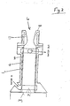
- FIG 2 illustrates an alternative combustion chamber construction in which a variety of insert components embodying the invention have been demonstrated.
- the construction again comprises a metal casing 1 having a closed end 3 having an injector 7 and an open end 5 with a nozzle insert 13 fitted in the inner wall of the chamber.
- the casing has an aluminium lining 4, a short expansion cone 8 (instead of the large expansion cone 11 in Figure 1) and a water cooling channel 10 between the casing 1 and lining 4.
- Programme 1 as follows describes the production and investigation by use of various nozzle inserts embodying the invention made from converted graphite.
- Programme 2 describes the use of converted carbon-carbon composites for use as insert components embodying the invention.
- Nozzle inserts were prepared by the application to graphite substrates (that had previously been machined to the desired contour) of the process described in US Patent No. 875693 herein described as "Process A”, described in the following reference: "The Performance of siliconised graphite as a mating face in mechanical scales", ASLE Preprint No. 76-AM-6B-3, by Paxton, R. R., Massaro, A. J., Strugala, E. W., of the Pure Carbon Co., St. Mary's Pennsylvania, which was a paper read at the 31st Annual Meeting of the American Society of Lubricating Engineers, Philadelphia, Pennsylvania, May 10th-13th, 1976.
- Process A is a technique for converting the surface layers of carbon to ⁇ -silicon carbide, up to a depth of 5 mm. Typical properties of silicon carbide formed by this technique are listed in Table 1 as follows.
- Process A the components are contained in a reaction vessel at a temperature in the region of 1700°C-1900°C, e.g. 1800°C, above a mixture of silicon carbide and silica. At this temperature a silicon monoxide atmosphere is created and the following general reaction takes place SiO + 2C SiC + CO Because the components are in contact with vapour only during the period of conversion, the quality of surface finish remains unaffected by the process.
- Unconverted nozzle inserts were of two sizes, 32 mm and 51 mm at the throat (minimum internal diameter), to match various injectors and valves of the rocket combustion chamber already available. Two alternative susstrate materials were used, Le Carbone grade P5890 (Trade Mark) and Union Carbide grade ATJ (Trade Mark). Nozzle inserts were assembled as either complete combustion chamber and nozzle assemblies incorporating ablative REFRASIL (Trade Mark) linings as shown in Fig. 1 or flanged nozzle assemblies that could be used with either water cooled combustion chambers (Fig. 2), or ablatively cooled combustion chambers. A list of test components used in Programme 1 is shown in Table 2 as follows.
- the propellant used was the known composition IRFNA-MAF-1 which comprises the following two components:
- halogen containing species represents only one half of one per cent of the total combustion product mixture.
- quantities of molten silica and pyrolysed resin also pass through the nozzle.
- Table 4 The results of test firings obtained with the specimens listed in Table 2 are shown in Table 4 below. To facilitate a cohesive analysis of these results it is necessary to draw them together into groups, where each group has the minimum number of variables. The format of Table 4 reflects this need.
- Firings 293-295 reveal that the conversion of 0.8 mm of the surface provided an improvement in resistance to attack for a few seconds, with eventual failure of the SiC layer leading to a resumption in the rapid erosion of graphite in the throat and subsonic regions.
- ATJ substrate with various depths of SiC conversion (Firings 1004, 1012, 3012, 1005-1009, 365-368, 1095-1097, 1107)
- ATJ substrate 2 mm conversion depth, oxidant rich conditions (Firings 1039-1047, 1067-1069, 1104-1106)
- Firings 1093, 1040, 1056, 1067, 1068, 1104 and 1106 were directed at a comparison of the ability of SiC layers to withstand steady state pulsed duty cycles (on/off fuel supply cycles). The results indicate that duty cycles involving two pulses were within the capabilities of a 2.0 mm SiC layer, there being no damage following 5 on-5 off-5 on and 10 on-5 off-10 on cycles (times in seconds). The imposition of a single 38 second firing (1056) revealed that the SiC layer was capable of withstanding long total firing times in ablatively cooled assemblies, confirming also that durability of nozzles fired under oxidant rich conditions was not a function of cooling.
- SiC layers formed by conversion from graphite remain subject to some degree to the limitations on thermal cycling normally associated with SiC layers formed on graphite by conventional means.
- An engine in which the boundary conditions are cooler and less oxidising than those described above can provide prolongation of the life of the Procss A converted SiC layer such that it is suitable for use in an engine having a lifetime of minutes rather than seconds.
- Such conditions may be obtained by injecting fuel along the walls of the combustion chamber in the manner described by Berman, K., and Andrysiak, S. J., in the article entitled “Barrier Film Cooling Study", J. Spacecraft, Vol. 9, No. 3, March 1972.
- the cones were used to demonstrate the Process A conversion of carbon-carbon rocket combustion chamber components whereas the boards were used to demonstrate the effect on flexural strength of Process A conversion of carbon-carbon composites.
- the flexural strength measurement apparatus could only be used with flat samples.
- the Process A converted expansion cones may be used in a rocket engine construction (i.e. as the cone 11) shown in Figure 1 and provide improved erosion resistance as described above.
- the nozzle inserts 13 used in the respective constructions shown in Figures 1 and 2 may also be made from Process A converted carbon-carbon composites produced in the same manner as the expansion cones described above (with reference to Tables 5 and 6).
Applications Claiming Priority (2)
| Application Number | Priority Date | Filing Date | Title |
|---|---|---|---|
| GB8613472 | 1986-06-04 | ||
| GB868613472A GB8613472D0 (en) | 1986-06-04 | 1986-06-04 | Components for propellant engine combustion chambers |
Publications (2)
| Publication Number | Publication Date |
|---|---|
| EP0249393A2 true EP0249393A2 (fr) | 1987-12-16 |
| EP0249393A3 EP0249393A3 (fr) | 1989-03-08 |
Family
ID=10598879
Family Applications (1)
| Application Number | Title | Priority Date | Filing Date |
|---|---|---|---|
| EP87304932A Withdrawn EP0249393A3 (fr) | 1986-06-04 | 1987-06-03 | Eléments pour une chambre de combustion d'une fusée |
Country Status (2)
| Country | Link |
|---|---|
| EP (1) | EP0249393A3 (fr) |
| GB (1) | GB8613472D0 (fr) |
Cited By (3)
| Publication number | Priority date | Publication date | Assignee | Title |
|---|---|---|---|---|
| FR2652615A1 (fr) * | 1989-10-04 | 1991-04-05 | Europ Propulsion | Chambre de combustion de propulseur. |
| WO1999004156A1 (fr) * | 1997-07-17 | 1999-01-28 | Deutsches Zentrum für Luft- und Raumfahrt e.V. | Chambre de combustion et procede permettant de realiser une chambre de combustion |
| FR2825417A1 (fr) * | 2001-06-01 | 2002-12-06 | Astrium Gmbh | Chambre de combustion avec enveloppe interne constituee d'un materiau composite ceramique et procedes pour sa fabrication |
Citations (3)
| Publication number | Priority date | Publication date | Assignee | Title |
|---|---|---|---|---|
| US2677627A (en) * | 1951-10-26 | 1954-05-04 | Norton Co | Process of coating carbonaceous material with silicon carbide |
| US2849860A (en) * | 1955-10-17 | 1958-09-02 | Norton Co | Rocket motor with recrystallized silicon carbide throat insert |
| US3520478A (en) * | 1966-06-06 | 1970-07-14 | Stackpole Carbon Co | Rocket nozzles |
-
1986
- 1986-06-04 GB GB868613472A patent/GB8613472D0/en active Pending
-
1987
- 1987-06-03 EP EP87304932A patent/EP0249393A3/fr not_active Withdrawn
Patent Citations (3)
| Publication number | Priority date | Publication date | Assignee | Title |
|---|---|---|---|---|
| US2677627A (en) * | 1951-10-26 | 1954-05-04 | Norton Co | Process of coating carbonaceous material with silicon carbide |
| US2849860A (en) * | 1955-10-17 | 1958-09-02 | Norton Co | Rocket motor with recrystallized silicon carbide throat insert |
| US3520478A (en) * | 1966-06-06 | 1970-07-14 | Stackpole Carbon Co | Rocket nozzles |
Non-Patent Citations (4)
| Title |
|---|
| ASLE 31ST ANNUAL MEETING, 10th-13th May 1976, Philadelphia, PA, ASLE preprint no. 76AM-6B-3, pages 1-6, American Society of Lubrication Engineers, Illinois, US; R.R. PAXTON et al.: "Performance of siliconized graphite as a mating face in mechanical seals" * |
| BUNDESMINISTERIUM F]R FORSCHUNG UND TECHNOLOGIE, FORSCHUNGSBERICHT T 79-155, December 1979, pages 21-25, Meitingen, DE; H. B\DER et al.: "Entwicklung hochwarmfester Formkörper aus SiC, insbesondere für den Gasturbinenbau" * |
| JOURNAL OF SPACECRAFT AND POCKETS, vol. 9, no. 3, March 1972, pages 152-157, New York, US; K. BERMAN et al.: "Barrier film cooling study" * |
| METAL PROGRESS, vol. 73, no. 6, June 1958, pages 82-83, Ohio, US; R.C. KOPITUK: "Materials for rocket engines" * |
Cited By (6)
| Publication number | Priority date | Publication date | Assignee | Title |
|---|---|---|---|---|
| FR2652615A1 (fr) * | 1989-10-04 | 1991-04-05 | Europ Propulsion | Chambre de combustion de propulseur. |
| EP0421865A1 (fr) * | 1989-10-04 | 1991-04-10 | Societe Europeenne De Propulsion (S.E.P.) S.A. | Chambre de combustion de propulseur |
| WO1999004156A1 (fr) * | 1997-07-17 | 1999-01-28 | Deutsches Zentrum für Luft- und Raumfahrt e.V. | Chambre de combustion et procede permettant de realiser une chambre de combustion |
| US6151887A (en) * | 1997-07-17 | 2000-11-28 | Deutsches Zentrum Fuer Luft- Und Raumfahrt E.V. | Combustion chamber for rocket engine |
| FR2825417A1 (fr) * | 2001-06-01 | 2002-12-06 | Astrium Gmbh | Chambre de combustion avec enveloppe interne constituee d'un materiau composite ceramique et procedes pour sa fabrication |
| US7293403B2 (en) | 2001-06-01 | 2007-11-13 | Astrium Gmbh | Combustion chamber with internal jacket made of a ceramic composite material and process for manufacture |
Also Published As
| Publication number | Publication date |
|---|---|
| EP0249393A3 (fr) | 1989-03-08 |
| GB8613472D0 (en) | 1986-08-20 |
Similar Documents
| Publication | Publication Date | Title |
|---|---|---|
| US4397901A (en) | Composite article and method of making same | |
| US4580524A (en) | Process for the preparation of fiber-reinforced ceramic composites by chemical vapor deposition | |
| US4671997A (en) | Gas turbine composite parts | |
| US6723382B2 (en) | Method for fabricating ceramic matrix composite | |
| CA2010343C (fr) | Methode de preparation d'un materiau mixte pour matrice de ceramique, possedant une plus grande resistance | |
| Johnson et al. | Mechanical properties of joined silicon nitride | |
| JP2000219576A (ja) | セラミックス基複合部材及びその製造方法 | |
| Grathwohl et al. | Creep of reaction-bonded silicon nitride | |
| EP0249393A2 (fr) | Eléments pour une chambre de combustion d'une fusée | |
| Schoenman | 4000 F materials for low-thrust rocket engines | |
| Johnston et al. | Performance of rocket nozzle materials with several solid propellants | |
| Moeller et al. | Fiber‐Reinforced Ceramic Composites | |
| Bouillon et al. | An improved long life duration CMC for jet aircraft engine applications | |
| US5525372A (en) | Method of manufacturing hybrid fiber-reinforced composite nozzle material | |
| KLEPPING | Evaluation of silicon carbide converted carbon components for liquidrocket engine applications | |
| US20060144037A1 (en) | Rocket nozzle material | |
| JP2812019B2 (ja) | 炭素繊維/炭素複合材 | |
| JP2001146486A (ja) | セラミックス基複合材の製造方法及び製造装置 | |
| Winter et al. | Experimental Evaluation of Throat Inserts in a Storable-Propellant Rocket Engine | |
| Pierce et al. | Tensile behavior of SiC/C and Rene'41 following isothermal exposure and thermal fatigue | |
| WOODS | Pyrolytic graphite for high pressure, high temperature applications | |
| KUSAKA et al. | Fabrication and test of a carbon-carbon composite combustion chamber for a low thrust storable engine | |
| Kravetskii et al. | Carbon-ceramic composite materials with protective erosion-resistant coatings | |
| Godfrey et al. | The resistance of silicon nitride ceramics to thermal shock and other hostile environments | |
| Freche et al. | Performance of rocket nozzle materials with several solid propellants |
Legal Events
| Date | Code | Title | Description |
|---|---|---|---|
| PUAI | Public reference made under article 153(3) epc to a published international application that has entered the european phase |
Free format text: ORIGINAL CODE: 0009012 |
|
| AK | Designated contracting states |
Kind code of ref document: A2 Designated state(s): DE FR GB SE |
|
| PUAL | Search report despatched |
Free format text: ORIGINAL CODE: 0009013 |
|
| AK | Designated contracting states |
Kind code of ref document: A3 Designated state(s): DE FR GB SE |
|
| 17P | Request for examination filed |
Effective date: 19890508 |
|
| 17Q | First examination report despatched |
Effective date: 19890912 |
|
| STAA | Information on the status of an ep patent application or granted ep patent |
Free format text: STATUS: THE APPLICATION IS DEEMED TO BE WITHDRAWN |
|
| 18D | Application deemed to be withdrawn |
Effective date: 19900123 |
|
| RIN1 | Information on inventor provided before grant (corrected) |
Inventor name: EVANS, CHRISTOPHER CHARLES, DR. Inventor name: KLEPPING, ANTHONY HERBERT, DR. Inventor name: PAUL, MALCOLM FREDERICK Inventor name: JACKMAN, PAUL ERIC |