EP0248729B1 - Monodimensional cosine transform calculators and image coding and decoding devices using such calculators - Google Patents
Monodimensional cosine transform calculators and image coding and decoding devices using such calculators Download PDFInfo
- Publication number
- EP0248729B1 EP0248729B1 EP87401233A EP87401233A EP0248729B1 EP 0248729 B1 EP0248729 B1 EP 0248729B1 EP 87401233 A EP87401233 A EP 87401233A EP 87401233 A EP87401233 A EP 87401233A EP 0248729 B1 EP0248729 B1 EP 0248729B1
- Authority
- EP
- European Patent Office
- Prior art keywords
- values
- input
- value
- transformed
- output
- Prior art date
- Legal status (The legal status is an assumption and is not a legal conclusion. Google has not performed a legal analysis and makes no representation as to the accuracy of the status listed.)
- Expired - Lifetime
Links
Images


Classifications
-
- G—PHYSICS
- G06—COMPUTING; CALCULATING OR COUNTING
- G06F—ELECTRIC DIGITAL DATA PROCESSING
- G06F17/00—Digital computing or data processing equipment or methods, specially adapted for specific functions
- G06F17/10—Complex mathematical operations
- G06F17/14—Fourier, Walsh or analogous domain transformations, e.g. Laplace, Hilbert, Karhunen-Loeve, transforms
-
- H—ELECTRICITY
- H04—ELECTRIC COMMUNICATION TECHNIQUE
- H04N—PICTORIAL COMMUNICATION, e.g. TELEVISION
- H04N19/00—Methods or arrangements for coding, decoding, compressing or decompressing digital video signals
- H04N19/60—Methods or arrangements for coding, decoding, compressing or decompressing digital video signals using transform coding
-
- G—PHYSICS
- G06—COMPUTING; CALCULATING OR COUNTING
- G06F—ELECTRIC DIGITAL DATA PROCESSING
- G06F17/00—Digital computing or data processing equipment or methods, specially adapted for specific functions
- G06F17/10—Complex mathematical operations
- G06F17/14—Fourier, Walsh or analogous domain transformations, e.g. Laplace, Hilbert, Karhunen-Loeve, transforms
- G06F17/141—Discrete Fourier transforms
- G06F17/142—Fast Fourier transforms, e.g. using a Cooley-Tukey type algorithm
-
- G—PHYSICS
- G06—COMPUTING; CALCULATING OR COUNTING
- G06F—ELECTRIC DIGITAL DATA PROCESSING
- G06F17/00—Digital computing or data processing equipment or methods, specially adapted for specific functions
- G06F17/10—Complex mathematical operations
- G06F17/14—Fourier, Walsh or analogous domain transformations, e.g. Laplace, Hilbert, Karhunen-Loeve, transforms
- G06F17/147—Discrete orthonormal transforms, e.g. discrete cosine transform, discrete sine transform, and variations therefrom, e.g. modified discrete cosine transform, integer transforms approximating the discrete cosine transform
Definitions
- the invention relates to devices for calculating cosine transforms, which are used in particular for coding images in order to reduce the amount of information representing these images. This reduction in information makes it possible to transmit or store images by means having a limited rate of information.
- This coding makes a matrix of N x N values, called direct cosine transforms, correspond to a matrix of N x N values representative of a block of N x N points of the image to be coded.
- This image is generally divided into square portions each consisting of a block of N x N points.
- a weighting of the transformed values makes it possible to reduce the amount of information representative of an image.
- Decoding consists in applying an inverse weighting then an inverse cosine transformation which makes correspond a matrix of N x N inverse transformed values to a matrix of N x N direct transformed. Like coding, decoding is carried out by blocks of N x N picture points.
- the inverse transformed values are provided by the two-dimensional inverse cosine transformation by applying the following formula:
- This two-dimensional cosine transformation can be broken down into two one-dimensional cosine transformations and the calculation of the two-dimensional transforms can be carried out by means of two devices for calculating one-dimensional transforms, connected in cascade.
- the one-dimensional cosine transformation is carried out according to the following formulas:
- the object of the invention is to produce, for a low cost, a device for calculating direct cosine transforms mono-dimensional and a device for calculating inverse cosine transforms mono-dimensional having a simpler structure than the devices implementing the 'algorithm of Chen et al, to transform sequences of 16 values.
- the object of the invention is also to provide a coding device and a decoding device applying in real time the two-dimensional cosine transformation to video images meeting the standards of conventional television.
- the subject of the invention is in particular a device for calculating direct mono-dimensional cosine transforms and a device for calculating inverse mono-dimensional cosine transforms implementing two algorithms derived from known algorithms, described by Beyeong Gi Lee in "A new algorithm to compute the discrete cosine transform "- IEEE Trans. on Acoustic, Speech and Signal Processing. Vol.ASSP-32, No. 6, pp1243-1245, December 1984.
- Beyeong Gi Lee are modified to allow their implementation by devices for calculating transformed consisting essentially of a small number of RAMs and '' a small number of elementary computing devices achievable by means of commercially available integrated circuits, and capable of operating at a rate equal to the rate of analysis of the image points in the standards of conventional television.
- a subject of the invention is also a coding device and a device for decoding images by the two-dimensional cosine transformation, comprising two devices for calculating one-dimensional cosine transforms.
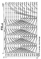
- FIG. 1 represents the distribution over time of all the calculation operations carried out according to the algorithm of Beyeong Gi Lee. These calculation operations provide 16 values F ⁇ (0), F ⁇ (1), ..., F ⁇ (15) which are equal, to within a factor, to the 16 transformed values F (0), F (1), .. ., F (15) of 16 values to transform: f (0), f (15), f (7), f (8), f (3), f (12), f (4), f (11 ), f (1), f (14), f (6), f (9), f (2), f (13), f (5), f (10).
- This calculation diagram applies formula (3), without taking into account the factors 2 NOT . c (k), therefore:
- This diagram has two time axes: a horizontal axis oriented from left to right and a vertical axis oriented from top to bottom, which define the order of operations.
- the 16 values to transform f (0), f (15), ..., f (10) are available successively. If, for example, they represent the luminance of a linear block of 16 points of an image, they are available at the rate of sampling of these image points. These values are obtained in order (f0), f (1), ..., f (15) during sampling. They are then put in the order f (0), f (15), f (7), ..., f (10) to be able to apply the algorithm.
- Each value to be transformed, each intermediate value, and each value transformed, is represented by a point.
- the operations making it possible to obtain the intermediate values and the transformed values are represented by solid or dotted lines.
- the convergence of two continuous lines symbolizes an addition.
- the convergence of a continuous line and a broken line symbolizes a subtraction.
- a horizontal line surmounted by a numerical value symbolizes a multiplication by this numerical value, the absence of a numerical value symbolizing a transmission with a coefficient 1.
- FIGS. 2 and 3 are extracts from FIG. 1, giving examples of operations symbolized in this FIG. 1.
- FIG. 2 represents an extract from the first calculation line, corresponding to the value to be transformed f (0), and of the ninth calculation line corresponding to the value to be transformed f (15).
- the first intermediate value is equal to the sum of f (0) and f (15) because the point representing this first intermediate value is connected by a solid line to the point representing the value at transform f (0) and by a continuous line to the value representing f (15).
- the second intermediate value is also equal to f (0) + f (15) because it is connected by a solid line not surmounted by a numerical value, to the first intermediate value.
- the first intermediate value is equal to f (0) - f (15) because the point representing it is linked by a dotted line to the point representing the value to be transformed f (15 ), and by a continuous line to the value to transform f (0).
- the second intermediate value on the line corresponding to f (15) is equal to because it is connected by a solid line surmounted by the value at the point representing the second intermediate value, on the line corresponding to f (15).
- FIG. 3 represents an extract from FIG. 1 corresponding to a part of the calculation lines providing the transformed values F ⁇ (4) and F ⁇ (12). Only the last three intermediate values of these lines are shown. The calculations are considered from a first intermediate value g1 and a first intermediate value g2 respectively.
- the second intermediate value is equal to g1 + g2 because it is connected by solid lines to the intermediate values g1 and g2.
- the third intermediate value on this same line, and the transformed value F ⁇ (4), are equal to g1 + g2 because the calculation is reduced simply to a transmission of the second intermediate value, without delay.
- the second intermediate value, the third intermediate value, and the transformed value F ⁇ (12) are equal to g2 because the calculations are reduced to a transmission, without delay.
- the Beyeong Gi Lee algorithm is modified in accordance with Figure 4.
- the order of the values to be transformed is modified: f (0), f (15), f (7), f (8), f (3), f (12), f (4), f (11), f (1), f (14), f (6), f (9), f (2), f (13), f (5), f (10).
- the lines of points representing the intermediate values are swapped in the same way as the values to be transformed.
- the connections between the points representing the values to be transformed, the intermediate values, and the transformed values are maintained during these permutations as if the lines representing these connections were elastic threads.
- the order of the transformed values obtained is therefore also modified: F ⁇ (0), F ⁇ (1), F ⁇ (2), F ⁇ (3), ..., F ⁇ (15). It should be noted that the values to be transformed are no longer in the order of increasing indices but, on the other hand, the transformed values are now in the order of increasing indices.
- the most remarkable property of this modified diagram is that it has four columns of calculations COL 1, COL 2, COL 3, COL 4, which are identical. On the other hand, each of these calculation columns consists of eight operations such as that represented in FIG. 2.
- Each of these eight operations makes it possible to obtain a value of the form A + B and a value of the form (A - B) ⁇ D from a first operand of value A, a second operand of value B, and a third operand of value D which is a predetermined constant.
- This modified calculation diagram therefore makes it possible to obtain 64 intermediate values corresponding to the four columns of identical operations, COL 1 to COL 4, by means of a single calculation device having a first and a second input d operand receiving two values A and B respectively, having a third operand input receiving a value D and having two outputs providing respectively two values A + B and (A - B) ⁇ D. If such a calculation device provides pairs of values at a rate twice the rate at which the values to be transformed are available, then a single calculation device makes it possible to obtain the 64 intermediate values during the duration corresponding to 16 values to be transformed. This therefore results in a very simple structure of the device for calculating the transforms.
- the other transformed values resulting from several additions located in the last three columns of operations can be considered as resulting from chain additions, that is to say that the calculation diagram d such a transformed value comprises a horizontal line, indicating the transmission of an intermediate value obtained previously on the same line, and an oblique line indicating the addition of another intermediate value obtained on another line.
- the transformed value F ⁇ (3) is obtained from an intermediate value calculated on the fourth line of the diagram, line corresponding to F ⁇ (4), to which is first added an intermediate value calculated on the corresponding line to F ⁇ (7), then to which is added an intermediate value calculated on the line corresponding to the transformed value F ⁇ (5).
- These chain addition operations make it possible to obtain an intermediate value, or a transform value, by providing for each addition a single operand to an adder, as soon as the addition chain has been initialized, which is faster. and simpler to perform than supplying two operands to an adder.
- the first addition G + H requires two calculation periods to load the values G and H consecutively, but all the other additions only require a single calculation period to load a new operand.
- This second peculiarity of the structure of the calculation diagram also makes it possible to simplify the device for implementing the algorithm. If a calculation device performs chain additions at a rate equal to twice that where the values to be transformed are available, it can easily carry out the 17 additions appearing on the diagram and provide the 16 transformed values as output, for the corresponding duration to 16 values to transform. A single calculation device carrying out chain additions will then be sufficient.
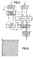
- FIG. 5 represents the block diagram of an exemplary embodiment of a device for calculating one-dimensional direct cosine transforms, according to the invention.
- This example includes: an input terminal 1 receiving sequences of 16 digital values which can be values representative of a linear block of 16 image points or be 16 transformed cosine direct mono-dimensional values provided by another device for calculating mono-dimensional direct cosine transforms, two devices according to the invention being associated in series to produce a device for calculating bi-dimensional direct cosine transforms; an input terminal 2 receiving a synchronization signal; an input memory 3; control means 5; first and second means for storing intermediate values, 4 and 8; first and second calculation means, 6 and 7; an order change device 9; an output terminal 11 providing sequences of 16 transformed values calculated according to the calculation diagram of FIG. 14; and an output terminal 13 providing a synchronization signal.
- the input memory 3 has a data input connected to the input terminal 1 to receive each value to be transformed, in the form of a 16-bit binary word, and has two outputs connected respectively to a first input of operand and to a second operand input of the computing means 6 for supplying it respectively with two 16-bit binary words.
- the means 4 for storing intermediate values have a first and second output connected in parallel with the outputs of the input memory 3 to the first and second operand inputs of the computing means 6.
- the outputs of the means 4 and of the memory 3 can take three states, a high impedance state making it possible to avoid conflicts between these outputs.
- the calculation means 6 have a first output connected to a first data input of the means 4 and to a first data input of the means 8 and providing a binary word of 16 bits.
- the calculation means 6 also have a second output connected to a second data input of the means 4 and to a second data input of the means 8 and providing them with a 16-bit binary word.
- the means 8 have: a third data input connected to an output of the second calculation means 7 for receiving a binary word of 16 bits; a first output connected to an operand input of the calculation means 7 to supply them with a 16-bit binary word; and a second output connected to an input of the order change device 9 to supply it with a 16-bit binary word.
- the device 9 has an output connected to the output terminal 11 of the embodiment shown, to provide it with a 16-bit binary word constituting a transformed value.
- the control means 5 are connected to the input terminal 2 to receive the synchronization signal.
- the synchronization signal corresponds to 16 sequences of 16 values to be transformed, that is to say a block of 16 ⁇ 16 image points.
- the means 5 have an output connected to the output terminal 13 to supply a synchronization signal corresponding to 16 sequences of 16 transformed values supplied by the output terminal 11. This synchronization signal makes it possible to synchronize a second device for calculating cosine transforms direct one-dimensional or a device for coding and transmitting transformed values.
- the control means 5 also have other outputs, connected by connections not shown, to control inputs of the input memory 3, means 4 and 8 for storing intermediate values, calculation means 6 and 7 , and the order change device 9. They provide a clock signal whose rhythm is twice higher than the rate at which the values to be transformed are applied to input terminal 1. They supply control signals according to a cycle whose duration is equal to 32 clock periods and corresponds to 16 values to be transformed, for controlling the calculation means 6 and 7, the storage means 4 and 8, and the input memory 3; and they supply control signals for controlling the device 9, according to a cycle whose duration is 512 clock periods, which corresponds to 16 ⁇ 16 values to be transformed.
- the input memory 3 has the function of storing one by one the values to be transformed and of restoring them two by two to constitute the two operands used by the first calculation means 6 to carry out the operations represented in the first column COL 1 of the calculation diagram of figure 4.
- the values to transform are applied in the order indicated on the diagram of figure 4: f (0), f (15), f (7), f (8), ... , f (10), which is not the order of analysis of the corresponding image points.
- the means for sampling, digitizing, and changing the order of the values f (0), f (1), ..., f (15) are not shown. They are in the field of classical technique.
- the role of the means 4 is to store two by two the intermediate values provided by the outputs of the calculation means 6 and then to supply them to the two operand inputs of the calculation means 6 to carry out the operations represented in the second column COL 2, the third column COL 3, and the fourth column COL 4, of the operations represented in FIG. 4.
- the calculation means 6 respectively supply on their two outputs values of the form A + B and (A - B) ⁇ D when two values of the form A and B were applied respectively to their two operand inputs.
- the value D of the third operand is a constant selected by a control signal supplied by the means 5.
- the role of the means 8 is to store the pairs of intermediate values supplied by the two outputs of the calculation means 6 and then to supply these values individually either at the input of the calculation means 7 or at the input of the device for changing order 9.
- the means 8 also store intermediate values supplied by the calculation means 7 to the third data entry of the means 8.
- the order change device 9 performs an order change of the transformed values supplied by the second output of the means 8 for storing intermediate values.
- the change of order depends on the subsequent use of the transformed values.
- the device 9 stores 16 sequences of 16 transformed values, which are calculated line after line according to the following table:
- this exemplary embodiment constitutes the second device for calculating one-dimensional cosine transforms
- its output terminal 11 provides transformed values F ⁇ (u, v) in an order suitable for subsequent processing, generally intended to reduce the amount of information representing an image.
- This adapted order is generally the order defined by FIG. 6 and which is said to be zig-zag order.
- This order corresponds to a classification of the transformed values according to the increasing values of u and v, which corresponds to statistically decreasing absolute values for the transformed values.
- the choice of the format of the values is particularly important for the production of the device according to the invention.
- the calculation means 6 and 8 work on values having a predetermined format: 13 bits for the integer part and 3 bits for the decimal part. This format was determined by calculating an upper bound for each of the intermediate values and for each of the transformed values encountered in the diagram in FIG. 4, as a function of a upper bound for the values to be transformed. When these consist of luminance values, they are coded on 8 bits and are between 0 and + 255. The intermediate values and the transformed values then have the upper bounds + 4080 and - 2778. To avoid any overflow of the format , these upper bound values lead to choosing a 13-bit format for the whole part, among which a bit dedicated to the sign. Since, on the other hand, commercially available multiplier circuits commonly process 16-bit values, a 3-bit format for the decimal part was chosen.
- a device for calculating two-dimensional cosine transforms comprises, in series, two devices for calculating one-dimensional transforms.
- a first device receives values to be transformed which are luminance values between 0 and + 255 and which are represented by 8 bits. To avoid any overflow of the format during the calculations, these 8 bits constitute the 8 least significant bits among the 13 bits reserved for the integer part of the values applied to the input terminal 1.
- These values F ⁇ (u) have the predetermined format, comprising 13 bits for the whole part, including the sign bit, and 3 bits for the decimal part.
- the format of the values to be transformed defined previously for the first device for calculating one-dimensional cosine transforms does not include a decimal part, in other words the comma is fixed to the right of the least significant bit.
- F ⁇ (u) comprising 3 bits of decimal value
- FIG. 7 represents a more detailed block diagram of the exemplary embodiment represented in FIG. 5.
- the control means 5 consist of a clock 25 of frequency 22.5 MHz and of a sequencer 26.
- an image is sampled at a frequency of 13.5 MHz but the values representative of the points of this image are supplied to the device for calculating transforms at a frequency of 11.25 MHz because the suppression time between the image lines is recovered.
- the frequency of the clock 25 is twice the frequency at which the values to be transformed are applied to the input terminal 1.
- An output of the clock 25 is connected to an input of the sequencer 26.
- the sequencer 26 provides control signals to the entire transform calculation device with a period equal to 32 periods of the clock 25.
- sequencer 26 It is synchronized by the synchronization signal applied to the input terminal 2 and indicating the start of each block of 16 sequences of 16 values to transform.
- An output of the sequencer 26 supplies the output terminal 13 with a synchronization signal which can be used to synchronize a second device for calculating direct one-dimensional cosine transforms.
- a multiple output from sequencer 26 provides the control signals necessary for all of the elements making up the transform calculation device.
- the input memory 3 consists of a register 23 having a capacity of a word of 16 bits, and a random access memory 24: having a data input port connected to an output of the register 23, a first and a second data output port constituting the two outputs of the means 3, a double addressing port connected to the multiple output of the control means 5 and making it possible to respectively select the data leaving by the two output ports, and inputs control connected to the multiple output of the control means 5, to control a read or write.
- the register 23 has a clock input connected to the multiple output of the control means 5 for receiving a control signal having a period equal to two clock periods.
- the memory 24 is made up of four integrated circuits Am 29707 manufactured by the company AMD. It allows simultaneous reading of two data selected respectively by the two address ports or it allows simultaneous reading and writing at two addresses selected respectively by the two address ports, or it allows two readings respectively at the two selected addresses by the double address port and simultaneously writing to an address selected by one of the address ports. This kind of memory allows you to read and write simultaneously to the same address. It therefore makes it possible to simultaneously store and restore a continuous stream of values to be transformed applied to the input terminal 1.
- the memory 24 stores 16 values to be transformed, at the rate at which they are available on the input terminal 1, during the duration of 32 clock periods, and restores 8 values on each of the two output ports for the duration of eight clock periods.
- the means 4 for storing intermediate values consist of two separate memories, 21 and 22, separately storing the first operands and the second operands which are to be applied respectively to the first and to the second operand input of the calculation means 6.
- Each of memories 21 and 22 is made up of four integrated circuits Am 29707 and can store 16 words of 16 bits. Each of these memories has a single data input port and a single output port.
- the data input ports of the memories 21 and 22 constitute the two data inputs of the means 4 and the output ports constitute the two data outputs of the means 4.
- a memory addressing port 21 and a data port addressing of the memory 22 are connected in parallel to the multiple output of the control means 5. Read and write control inputs of the memories 21 and 22 are also connected to the multiple output of the control means 5.
- the means 4 consist of two separate memories 21 and 22 because they must simultaneously store two values which are supplied simultaneously by the calculation means 6 and simultaneously supply two operand values to the calculation means 6. It would be possible to use a single memory with dual input port and dual output port but a memory of this type is not fast enough in this application, in the current state of technology.
- the calculation means 6 comprise a calculation circuit 28 and two multiplexers 34 and 35 with two inputs and one output.
- the calculation circuit 28 has two input terminals 30 and 31 constituting the first and second operand input of the means 6, a control input terminal 29 connected to the multiple output of the control means 5, and two terminals 32 and 33.
- the output terminal 32 is connected to a first input of the multiplexer 34 and to a first input of the multiplexer 35.
- the output terminal 33 is connected to a second input of the multiplexer 34 and to a second input of the multiplexer 35.
- the output of the multiplexer 34 and the output of the multiplexer 35 constitute respectively the first and the second output of the means 6.
- the multiplexer 34 and the multiplexer 35 respectively have two control inputs connected in parallel to the multiple output of the control means 5 .
- the calculation circuit 28 provides on its output terminals 32 and 33 respectively a first result of the form A + B and a second result of the form (A - B) ⁇ D when a first operand of the form A and a second operand of the form B are applied respectively to the input terminal 30 and to the input terminal 31.
- a result provided by the terminal 32 is used either as the first operand, applied to the terminal input 30 after having been restored by the means 4, or as a second operand applied to the input terminal 31 after having been restored by the means 4.
- FIG. 4 it appears that the intermediate values located on the first eight lines in the first columns of the calculation diagram are of type A + B while the intermediate values located on the last eight rows are of type (A - B) ⁇ D.
- each operation performed by the calculation circuit 28 provides two results which are simultaneously future operands of type A or simultaneously future operands of type B.
- the calculation circuit 28 delays by a clock period the result of type A + B supplied by its output terminal 32 in order to successively write the two results of the same type, provided by each operation of the calculation circuit 28.
- the calculation means 8 comprise: four multiplexers, 36 to 39, each equivalent to a switch with one circuit and with two positions; two random access memories, 40 and 41, random access, with double address port.
- a first input of the multiplexer 36 and a first input of the multiplexer 37 respectively constitute the first and the second input of the computing means 8.
- a second input of the multiplexer 36 and a second input of the multiplexer 37 are connected together and constitute the third input of the means 8.
- An output of the multiplexer 36 and an output of the multiplexer 37 are connected respectively to a data input from memory 40 and to a data input from memory 41.
- An output of memory 40 is connected to a first input of multiplexer 38 and to a first input of multiplexer 39.
- An output of memory 41 is connected to a second input of the multiplexer 38 and to a second input of the multiplexer 39.
- An output of the multiplexer 38 and an output of the multiplexer 39 constitute respectively the first and the second output of the computing means 8.
- the multiplexers 36 to 39 each have a control input connected to an output of the control means 5.
- the memories 40 and 41 each have two address ports and a read and write control input connected to an output of the means Each of these memories consists of four integrated circuits of the AM 29707 type making it possible to store 16 words of 16 bits.
- the presence of the two memories 40 and 41 makes it possible to simultaneously store two values which are supplied simultaneously by the two outputs of the calculation means 6. Thus it is possible to store 16 values in eight clock periods.
- the two outputs of the storage means 8 make it possible to simultaneously supply a value to the calculation means 7 and a value to the order change device 9.
- the device 9 can receive 16 transformed values while the calculation means 7 can receive 16 intermediate values, necessary for the calculation of 17 additions, during the duration of a cycle of 32 clock periods.
- the switching of the values received at the inputs of the storage means 8 and of the values to be conveyed to the outputs of the storage means 8 is carried out by means of a series of control signals supplied by the control means 5 with a corresponding period at 32 clock periods.
- the order change device 9 consists of two registers 43 and 46 which can store a value of 16 bits, and two random access random access memories, 44 and 45.
- the registers 43 and 46 respectively constitute an input buffer and a output buffer connected respectively to the data input of the device 9 and to the output terminal 11.
- the output of the register 43 is connected to a data input of the memory 44 and to a data input of the memory 45.
- a input of register 46 is connected both to an output of memory 44 and to an output of memory 45.
- Memory 44 and memory 45 each have a address input and read and write control inputs respectively connected to the multiple output of the control means 5 by links not shown in FIG. 7.
- the memories 44 and 45 each consist of 4 integrated circuits Cy 7C122 manufactured by Cypress and having a capacity of 256 ⁇ 4 bits.
- the transformed values are stored in device 9 as they become available, then they are restored by device 9 in a different order.
- the control means 5 supply the address inputs of memories 44 and 45 respectively with two sets of address values corresponding to these two different orders. They supply one of the memories, 44 or 45, with write control signals and supply the other memory with read control signals, alternately with a period corresponding to 16 ⁇ 16 values. It should be noted that the transformed values are written at the rhythm where they are available, that is to say with a rhythm equal to the clock rhythm, whereas they are restored at a rhythm equal to the rhythm where the values at transform are applied to input terminal 1, that is to say with a rhythm half the speed of the clock used for the calculations.
- FIG. 8 represents a block diagram of an exemplary embodiment of the calculation circuit 28.
- This calculation circuit comprises: eight registers which can store a word of 16 bits, 50, 51, 54, 55, 57, 59, 60, 62 ; an adder 52; a subtractor 53; a barrel register 58; a read only memory 56; a multiplier 61.
- the input terminals 30 and 31 are respectively connected to an input of the register 50 and to an input of the register 51 to supply them with a first word of 16 bits constituting a first operand A and a second word of 16 bits constituting a second operand B.
- the output of register 50 is connected to a first input of adder 52 and to a first input of subtractor 53.
- the output of register 51 is connected to a second input of adder 52 and to a second input of the subtractor 53.
- the output of the adder 52 is connected to an input of the register 54.
- An output of the register 54 is connected to an input of the register 57.
- An output of the register 57 is connected to the output terminal 32 for it provide a 16-bit binary word representing the result A + B.
- the output of the subtractor 53 is connected to an input of the register 55.
- An output of the register 55 is connected to a data input of the barrel register 58.
- the barrel register 58 makes it possible to shift a word of 16 bits, by a number variable bit size determined by a binary word applied to a control input. This binary word has two bits and is supplied by a first output from the read-only memory 56.
- An output from the barrel register 58 is connected to an input from the register 59.
- An output from the register 59 is connected to a first input from the multiplier 61.
- the read-only memory 56 has a second output connected to an input of the register 60 to supply it with a 16-bit word, D1, and has a control input connected to the input terminal 29 to receive a binary 5-bit word constituting a address for this read-only memory 56.
- An output of the register 60 is connected to a second input of the multiplier 61.
- An output of the multiplier 61 is connected to an input of the register 62.
- An output of the register 62 is connected to the output terminal 33 for provide it with a 16-bit binary word representing the result (A - B) ⁇ D.
- Each of the registers of the calculation circuit 28 has a clock input, not shown, receiving the clock signal produced by the s control means 5.
- Multiplication by the predetermined value D is carried out, on the one hand, by means of the barrel register 58 producing an offset of 0, or 1, or 2, or 3 bits, and, on the other hand, by means of the multiplier 61
- the read-only memory 56 provides on the one hand a binary word D2 of two bits indicating the value of the offset to be produced by the barrel register 58 and, on the other hand, a binary word D1 of 16 bits constituting an operand applied to the second input of multiplier 61.
- the value of D is During the calculations represented on the diagram of figure 4, it is necessary to carry out multiplications by the following coefficients:
- the coefficients are between 0.5 and 1.
- Their representation with 0 bit for the whole part and 16 bits for the decimal part makes it possible to keep one and the same format for all the calculations in the device for calculating transforms. Indeed, after multiplication by a value represented by means of 13 bits for the whole part and 3 bits for the decimal part, the result has a format comprising 13 bits for the whole part and 19 bits for the decimal part, which gives again a format of 13 bits for the whole part and 3 bits for the decimal part after having carried out a truncation limited to the 16 most significant bits. This conservation of the format of 13 bits for the whole part and 3 bits for the decimal part, throughout the calculations, makes it possible to simplify the management of adders and subtractors.
- the coefficients are greater than 1. This poses a problem because the multiplication of one of these coefficients by a value represented in a format comprising 3 bits for the integer part and 13 bits for the decimal part would provide a result whose format would comprise 16 bits for the integer part and 16 bits for the decimal part. This result would therefore have a format of 16 bits for the whole part and 0 bits for the decimal part after a truncation limited to the 16 most significant bits. There would therefore be following such a multiplication, a loss of format comprising 13 bits for the whole part and 3 bits for the decimal part.
- a multiplication by the coefficients is performed, on the one hand, by shifting 1, 2, or 3 bits to the left on the value to be multiplied, to multiply this value by 2, 4, or 8, and, on the other hand, by multiplying the value thus obtained by a coefficient divided beforehand by 2 or 4, or 8, respectively.
- the offset achieved is 1 bit to the left and the values of the coefficient applied to the second input of the multiplier 61 are or, respectively.
- the memory 56 stores 15 words of 18 bits, each word comprising two bits controlling an offset, possibly zero, and 16 bits translating the value of the coefficient to be applied to the second input of the multiplier 61.
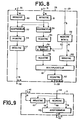
- FIG. 9 represents the block diagram of an exemplary embodiment of the calculation means 7.
- These include two registers, 67 and 68, having a capacity of a 16-bit word, and an adder 69.
- a data input from register 67 is connected to the input terminal 41 to receive a 16-bit word.
- An output of register 67 is connected to a data input of register 68 and a first input of adder 69.
- An output of register 68 is connected to a second input of adder 69.
- Each of registers 67 and 68 has a clock input connected to the input terminal 42 to receive the clock signal supplied by the control means 5.
- the adder 69 has an output connected to the output terminal 43 to supply it with a 16-bit word .
- the registers 67 and 68 are connected in series to simultaneously supply the adder 69 with two values which are applied successively to the input terminal 41.
- a sum of the form E + G is calculated by successively applying E then G to the input terminal 41 during two successive periods of the clock signal.
- To calculate a sum of the form (E + G) + H it suffices to apply successively E, then G, then H to the input terminal 41 during three successive periods of the clock signal.
- the multiplier 61 consists of an integrated circuit Am 29517A manufactured by the company AMD.
- the adders 52 and 69 each consist of integrated circuits 74F374, 74F381, and 74F182, manufactured by the company AMD.
- the subtractor 53 consists of the same integrated circuits.
- FIG. 10 represents a more detailed block diagram of the control means 5.
- These comprise: the clock 25, already mentioned previously; a binary counter 50, counting from 0 to 31; a binary counter 51, counting from 0 to 511; a read only memory 52; a read only memory 53; and a decoder 54.
- the counters 50 and 51 have a clock input connected to the output of the clock 25, and a reset input connected to the input terminal 2 receiving the synchronization signal corresponding to 16 sequences of 16 values to transform.
- the counter 51 has an output connected to an address input of the read only memory 53 and to an input of the decoder 54. This output provides a 9-bit word resulting from the counting.
- An output from decoder 54 provides a synchronization signal corresponding to the start of a block of 16 ⁇ 16 transformed values, when the counter 51 has counted 64 periods clock. This output is connected to the output terminal 13.
- An output of the counter 50 is connected to an input of the read-only memory 52 to supply it with a 5-bit word.
- the read only memory 52 has outputs providing address values and read and write control signals to the memories 24, 21, 22, 37, 56 and control signals to the multiplexers 34, 35, 36.
- the memory dead 53 has outputs providing addresses to memories 44 and 45, as well as read and write control signals.
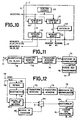
- FIG. 11 represents the block diagram of an exemplary embodiment of an image coding device according to the invention.
- This device comprises, in series, two devices for calculating direct one-dimensional cosine transforms, 73 and 74, produced according to the preceding description.
- the image coding device shown in FIG. 11 includes an input terminal 71 receiving a series of digital values f (i, j) representing the luminance values of the image points. These values are applied to the input of a device 72 for decomposing an image into blocks of 16 ⁇ 16 points corresponding to blocks of 16 ⁇ 16 luminance values.
- the device 72 provides, for each block, sixteen sequences of 16 values, each sequence corresponding to a portion of image line, and supplies a block synchronization signal, to the device 73 for calculating transforms.
- the image coding device also comprises a normalization device 75, a device 76 for coding transforms, and an output terminal 77, providing a series of transformed values, coded so as to reduce the amount of information.
- the input terminals 71 and 72 are respectively connected to an input of values to be transformed and to a synchronization input of the device 73.
- the device 73 has an output of transformed values and a synchronization output respectively connected to an input of values to transform and a synchronization input of the device 74.
- the device 74 has an output of transformed values and a synchronization output, connected respectively to a first and second input of the normalization device 75.
- the device 74 provides a series of transformed values F ⁇ (u, v) to the device 75.
- the normalization device 75 has an output connected to an input of the device 76 for coding the transforms to provide it with a series of values F ⁇ (u, v) formed by the transformed values multiplied by predetermined coefficients called normalization coefficients.
- the inverse cosine transformation is defined by the formula (2) mentioned above.
- the computation of the inverse transforms can be carried out according to the algorithm of Beyeong Gi Lee, by inverting the time axes on the computation diagram represented in figure 1.
- the values thus obtained are equal to the inverse transformed values f (i, j) defined by Figure 2, to within a factor, which depends on the value considered.
- This value f (i, j) can be expressed as a function of the value F ⁇ (u, v) obtained by applying twice the algorithm of Beyeong Gi Lee , and represented by formula (5):
- the normalization device 75 must therefore be inserted between the devices 73, 74 for calculating direct cosine transforms and the devices for calculating inverse cosine transforms, and must carry out the following multiplications:
- the multiplication coefficients are all powers of 2, which makes it possible to carry out these multiplications by means of a simple shift of the bits in a barrel register. On the contrary, if the multiplication by was performed in each of the one-dimensional transform calculation devices, this multiplication would be complicated to achieve, because is not an integer power of 2.
- the production of the standardization device 75 is within the reach of those skilled in the art. It can consist of a barrel register with a capacity of 16 bits and allowing a shift of 2 bits, or 1 bit, or 0 bit to the right, taking into account a fixed shift of 5 bits corresponding to the multiplication by 1 32 which is a factor common to all the values F ⁇ (u, v).
- the number of shift bits is controlled by a counting device receiving a clock signal supplied by a clock common to the devices 73 and 74, and reset to zero by a synchronization signal supplied by the device 74 when it supplies each sequence of 16 ⁇ 16 transformed values F ⁇ (u, v).
- the function 76 of coding the transforms has the function of reducing the amount of information to be transmitted. It can be carried out in accordance with the description given by: IEEE Transactions on Communications, VOL.COM-32, No. 3, March 1984 "Scene Adaptive Coder" by Wen-HSIUNG CHEN and WILLIAM K. PRATT.
- This coding consists in comparing the value of each transform with respect to a threshold value; to consider as null the transforms lower than the threshold value; to transmit the value of the non-zero transforms by a Huffman code and to transmit the addresses of these transforms in their matrices by means of range coding, the length of the ranges being itself coded by means of coding from Huffman. Only the first value, F ⁇ (0,0), of the matrix of the transforms is transmitted in absolute value.
- FIG. 12 represents the block diagram of a variant of this image coding device.
- This variant includes additional elements intended to improve the accuracy of the calculation of the transforms, the other elements being unchanged and bearing the same numerical references as in FIG. 11.
- This variant comprises: an input terminal 78 receiving a synchronization signal for each after 16 ⁇ 16 luminance values; an input terminal 79 receiving these sequences of values to be transformed; a device 82 for calculating an average value for each series of 16 ⁇ 16 luminance values; a delay device 80 providing a delay equal to the calculation time of the device 82; a subtractor 81; two devices for calculating direct one-dimensional cosine transforms, 73 and 74; a standardization device 75; a multiplexer 84 with two inputs and one output; means 83 for controlling this multiplexer 84; an adder 85; a device 76 for coding the transforms; and an output terminal 86.
- the input terminal 79 is connected to an input of the delay device 80 and to an input of the device 82 for calculating an average value.
- the subtractor 81 has a first input connected to an output of the delay device 80, a second input connected to an output of the device 82, and an output connected to the input of the values to be transformed from the device 73.
- the output of the calculation device 82 is also connected to a first input of the multiplexer 84.
- the multiplexer 84 also has: a second input receiving a permanent zero value, a control input connected to an output of the control means 83, and an output connected to a first input of the adder 85.
- the input terminal 78 receiving the synchronization signal, is connected to synchronization inputs of the device 73 and of the means 83.
- An output of transformed values of the device 73 is connected to an input of values to be transformed of the device 74.
- a synchronization output of device 73 is connected to a synchronization input of device 74.
- An output of transformed values of device 74 is connected to an input of normalization device 75.
- a synchronization output of device 74 is connected to a synchronization input of the device 75.
- An output of the normalization device 75 is connected to a second input of the adder 85.
- An output of the latter is connected to an input of the device 76 for coding the transforms.
- An output of the device 76 is connected to the output terminal 86.
- the subtractor 81 makes it possible to subtract from each of the luminance values of a block of 16 ⁇ 16 image points, the average value of these luminance values.
- the devices 73 and 74 then process values to be transformed having a reduced dynamic, which makes it possible to increase the precision of the calculations or else makes it possible to reduce the number of bits used to represent the values to be transformed. In the latter case, the calculation devices are simpler.
- the adder 85 makes it possible to find an exact value F ⁇ (0.0) by adding the average value supplied by the calculation device 82 to the first transformed value supplied by the normalization device 75 for each blocks of 16 ⁇ 16 image points.
- the adder 85 receives a zero value instead of the average value, thanks to the multiplexer 84 and the control means 83.
- the control means 83 control the multiplexer 84 in function of the rank of the transformed value supplied by the normalization device 75.
- the means 83 comprise a counting device receiving the clock signal from the devices 73 and 74, and reset to zero by means of the synchronization signal received by the terminal. entry 78.
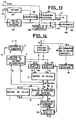
- FIG. 13 represents the block diagram of an alternative embodiment of the device for calculating one-dimensional cosine transforms according to the invention.
- This variant has improved accuracy by means similar to the means which have just been described. It comprises: a device 187 for calculating mono-dimensional cosine transforms similar to that shown in FIG. 7 and it further comprises: a device 182 for calculating an average value of a block of 16 values to be transformed; a delay device 180, providing a delay equal to the calculation time of the device 182; a subtractor 181; a multiplexer 184; means 183 for controlling the multiplexer 184; and an adder 185.
- An input terminal 179 is connected to an input of the delay device 180 and to an input of the device 182 for calculating a mean value, to provide them with sequences of 16 values to transform f (i, j).
- the subtractor 181 has a first input connected to an output of the delay device 180, a second input connected to an output of the device 182, and an output connected to an input terminal 1 of the device 187 to provide it with values to be transformed.
- the output of the computing device 182 is also connected to a first input of the multiplexer 184.
- the multiplexer 184 also has: a second input receiving a permanent zero value, a control input connected to an output of the control means 183, and an output connected to a first input of the adder 185.
- a second input of the adder 185 is connected to an output terminal 11 of the device 187 and an output is connected to an output terminal 186 to provide it with sequences of 16 transformed values mono-dimensional.
- An input terminal 178 receiving a synchronization signal corresponding to the start of each series of 16 values to be transformed, is connected to a synchronization input of the device 187 and to a synchronization input of the means 183.
- An output terminal 13 of the device 187 supplies another synchronization signal corresponding to the start of each series of 16 transformed values supplied by the output terminal 186.
- the subtractor 181 makes it possible to subtract from each of the values of a series of 16 values to be transformed, the average value of these.
- the device 187 then processes values to be transformed with reduced dynamics, which makes it possible to increase the precision of the calculations or else makes it possible to reduce the number of bits used to represent the values to be transformed. In the latter case, the computing device 187 can be simplified.
- the adder 185 makes it possible to find an exact value F ⁇ (0.0) by adding the average value supplied by the calculation device 182 to the first transformed value supplied by the device 187, for each sequence of 16 transformed values.
- the adder 185 receives a zero value instead of the average value, thanks to the multiplexer 184 and to the control means 183.
- the latter control the multiplexer 184 depending on the rank of the transformed value supplied by the device 187. They comprise a counting device receiving the clock signal from the device 187, and which is reset to zero by means of the synchronization signal received by the input terminal 178.
- a further improvement in the calculation accuracy of the one-dimensional transforms can be obtained by determining the format of the values no longer as a function of an upper bound of the values to be transformed but as a function of the effective maximum value of these values to be transformed. It is then possible to shift the bits representing these values as far as possible to the left while avoiding the risks of overflow during the calculations. Naturally, an opposite shift must be made at the output of the device for calculating one-dimensional transforms to return to a determined format.
- FIG. 14 represents the block diagram of an exemplary embodiment which is a variant of the exemplary embodiment represented in FIG. 5 and which comprises additional elements allowing an improvement of the precision by this means.
- additional elements are: three barrel registers, 92, 93, and 94; a device 90 for determining the maximum value in a series of 16 values to be transformed; and a device 91 for determining an offset.
- the device 90 has an input connected to the input terminal 1 to receive the sequences of 16 values to be transformed. It has an output connected to an input of the device 91.
- the latter calculates the number of bits, d, of an offset to be made at the input of the calculation means 6 and such that the values processed inside the calculation means 6 never exceed the capacity of these computing means 6.
- the offset calculated by the device 91 is produced by means of the barrel registers 92 and 93 which are interposed between the two output ports of the input memory 3 and the two operand inputs of the calculation means 6. These registers 92 and 93 are controlled by a binary word supplied by an output of the device 91.
- the barrel register 94 is interposed between the output of the order change device 9 and the output terminal 11 of the device for calculating one-dimensional direct cosine transforms.
- the barrel register 94 receives the same binary command word as the registers 92 and 93 but it performs a shift of d bits in the opposite direction to that achieved by the registers 92 and 93, in order to restore the transformed values in the fixed format. , comprising 13 bits for the whole part and 3 bits for the decimal part.
- This alternative embodiment relates to both the first and the second device for calculating one-dimensional cosine transforms constituting a coding device or a device for decoding images by two-dimensional cosine transformation.
- each device for calculating one-dimensional direct cosine transforms automatically determines the fixed format which will be used for the entire duration of the processing of 16 values, by shifting as much as possible, to the left, the values to be transformed without causing overflow during the calculations.
- This variant provides an improvement in precision when the values to be transformed have low dynamics, while remaining simpler than a floating point calculation device.
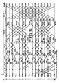
- Figure 15 represents the distribution in time of all the operations of computations carried out according to the algorithm of Beyeong Gi Lee, for the inverse mono-dimensional cosine transformation.
- These calculation operations provide 16 values f (0), f (1), ..., f (15) which are equal to the inverse transformed values of 16 transformed values F ⁇ (0), F ⁇ (8), F ⁇ (4) , F ⁇ (12), F ⁇ (2), F ⁇ (10), F ⁇ (6), F ⁇ (14), F ⁇ (1), F ⁇ (9), F ⁇ (5), F ⁇ (13), F ⁇ (3) , F ⁇ (11), F ⁇ (7), and F ⁇ (15) which are obtained by applying the Beyeong Gi Lee algorithm, modified or not, and which are equal, to a factor, to the 16 transformed values F (0 ), ..., F (15) of the transformed values given by the theoretical formula (1).
- This diagram can be deduced from the diagram represented in FIG. 1 and corresponding to the direct cosine transformation, by reversing the horizontal time axis.
- the operations represented on this diagram can be broken down into 7 columns denoted COL.1, COL.2, ..., COL.7.
- the Beyeong Gi Lee algorithm for reverse transformation requires a sequence of different operations in each of the columns, which complicates the implementation of the implementation device.
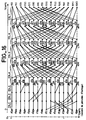
- the reverse transformation algorithm is modified in an analogous manner, in accordance with FIG. 16.
- This modification makes it possible to obtain a sequence of identical operations in column 4, the column 5, column 6, and column 7 of the diagram.
- references have been assigned to certain intermediate values provided by the calculation operations represented in FIG. 15.
- the intermediate values provided by the calculation operations in column 3 are noted: J (0), J (8 ), J (4), J (12), J (2), J (10), J (6), J (14), J (1), J (9), J (5), J (13 ), J (3), J (11), J (7), J (15).
- the intermediate values provided by the calculation operations of column 4 are noted K (0), ..., (K15).
- the intermediate values provided by the calculation operations of column 5 are noted L (0), ..., L (15).
- the intermediate values provided by the calculation operations of column 6 are noted M (0), ..., M (15).
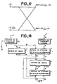
- FIG. 17 represents for example an extract from FIG. 15 representing the calculation of the values M (0) and M (2) from two intermediate values L (0) and L (2) calculated previously and from a value constant
- the calculation operations represented in columns 1, 2 and 3 of the diagram in FIG. 15 are simple additions or transmissions without modification.
- the diagram in FIG. 15 is modified so that the elementary operations, of the type shown in FIG. 17, can be carried out on two operands available consecutively. Consequently, the modification consists in successively modifying columns 4, 5, 6, and 7 to make the values constituting the two operands of each of the elementary operations consecutive.
- the modification will consist in modifying the order of the operations of computation of column 5 so that the intermediate values L (0) and L (2) are obtained consecutively in order to be able to then carry out immediately the elementary operation represented in this figure 17.
- the modification of the calculation diagram therefore consists of a set of elementary modifications consisting in permuting two intermediate values in the same column.
- the order of the intermediate values provided by the columns is as follows: the order of the values J (0), ..., (J15) is not modified.
- the order of the values provided by the calculations in column 4 is: K (0), K (4), K (2), K (6), K (1), K (5), K (3), K (7), K (8), K (12), K (10), K (14), K (9), K (13), K (11), K (15).
- the order of the values provided by the calculations in column 5 is: L (0), L (2), L (1), L (3), L (8), L (10), L (9), L (11), L (4), L (6), L (5), L (7), L (12), L (14), L (13), L (15).
- This modified calculation diagram therefore makes it possible to obtain 64 intermediate values, corresponding to the 4 columns of identical operations, COL.4, COL.5, COL.6, and COL.7, by means of a single computation device having a first and a second operand input receiving two values A and B, having a third operand input receiving a value D and having two outputs providing respectively two values A + DB and A - DB If such a device of calculation provides pairs of values at a rate twice that at which the transformed values are available, then a single calculation device is sufficient to obtain the 64 intermediate values for the duration corresponding to 16 transformed values.
- FIG. 18 represents the block diagram of an exemplary embodiment of a device for calculating inverse cosine transforms mono-dimensional according to the invention.
- This example includes: an input terminal 11 ⁇ receiving sequences of 16 digital values which can be 16 transformed cosine direct mono-dimensional values or else 16 transformed cosine direct two-dimensional values; in the latter case, two devices according to the invention are associated in series to produce a device for calculating two-dimensional inverse transforms; an input terminal 2 ⁇ receiving a synchronization signal; a 9 ⁇ order change device; 5 ⁇ control means; first and second intermediate value storage means, 4 ⁇ and 8 ⁇ ; first and second calculation means, 6 ⁇ and 7 ⁇ ; an output terminal 1 ⁇ supplying sequences of 16 inverse transformed values, calculated according to the calculation diagram in FIG. 16; and an output terminal 13 ⁇ providing a synchronization signal.
- the order change device 9 ⁇ has a data input connected to the input terminal 11 ⁇ to receive each transformed value, in the form of a 16-bit binary word and has an output connected to a first input of the means of 8 ⁇ storage to provide it with a 16-bit word.
- the means 8 ⁇ have a second input connected to an output of the calculation means 7 ⁇ which supplies them with a binary word of 16 bits.
- the means 8 ⁇ have a first and a second output respectively coupled to a first operand input and to a second operand input of the calculation means 6 ⁇ , and have a third output connected to an input of the calculation means 7 ⁇ to supply them a 16-bit binary word.
- the storage means 4 ⁇ have a first and a second output respectively coupled to the first and to the second input of the calculation means 6 ⁇ and coupled to the output terminal 1 ⁇ of the device for calculating inverse transforms.
- the calculation means 6 ⁇ have a first and a second output connected respectively to a first and a second input of the means 4 ⁇ .
- the calculation diagram of Figure 16 cannot be deduced from the calculation diagram of Figure 4 by a simple inversion of the horizontal time axis, however there are analogies with the diagram of Figure 4, and these analogies correspond to certain analogies in the structure of the device for calculating inverse transforms with respect to the structure of the device for calculating direct transforms.
- the elements analogues constituting the device for calculating inverse transforms are noted with the same reference numeral as in the device for calculating direct transforms, but with the prime index.
- the order change device 9 ⁇ performs a storage and an order change of 16 ⁇ 16 transformed values received by the input terminal 11 ⁇ to put the values to be transformed in the order represented on the left of the calculation diagram of the figure 16: F ⁇ (0), F ⁇ (8), ..., F ⁇ (7), F ⁇ (15).
- the first calculation device comprises a 9 ⁇ order change device storing 16 sequences of 16 values direct transforms which are generally available in the order shown in FIG. 6, the second calculation device storing 16 sequences of 16 transformed values which are supplied by the first device in the order of the lines, and restoring them in order columns.
- the role of the intermediate value storage means 8 ont is to store the intermediate values calculated by the calculation means 7 ⁇ and to restore them either at the input of these means 7 ⁇ or to the two operand inputs of the calculation means 6 Deutschen.
- the means 7 ⁇ and the means 8 ⁇ operate in a closed circuit to carry out the calculation operations located in columns 1, 2 and 3 of the diagram in FIG. 16.
- the means 7 ⁇ calculate a value of the form E + G from two operands E and G applied consecutively upon entry.
- the calculation means 6 ⁇ calculate two values A + D.B and A - D.B from two operands A and B applied consecutively to the two operand inputs.
- the arithmetic function performed by the calculation means 6 ⁇ is therefore different from that performed by the calculation means 6 of the device for calculating direct transforms.
- the means 4 ⁇ for storing intermediate values store the values calculated by the means 6 ⁇ and supply them either to the operand inputs of these means 6 ⁇ or to the output terminal 1 ⁇ of the device for calculating inverse transforms.
- the means 6 ⁇ and 4 ⁇ operate in a closed circuit to perform the calculations located in columns 5, 6 and 7 of the diagram in FIG. 16 then the inverse transformed values are supplied to output terminal 1 ⁇ .
- Control means 5 ⁇ generate clock signals and control signals for all of the elements of the inverse transform calculation device, in particular a clock signal controlling the calculations at a rate twice that at which the transformed values are applied to the input terminal 11 ⁇ .
- the means 5 ⁇ receive via the input terminal 2 ⁇ a synchronization signal corresponding to the start of each block of 16 ⁇ 16 direct transformed values applied successively to the input terminal 11 ⁇ . They supply the output terminal 13 ⁇ with a synchronization signal corresponding to the start of each block of 16 ⁇ 16 inverse transformed values supplied by the output terminal 1 ⁇ .
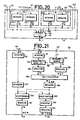
- FIGS 19 and 20 show a more detailed block diagram of this embodiment.
- the means 5 ⁇ include a clock 25 ⁇ providing a clock signal whose frequency is 22.5 MHz, and a sequencer 26 ⁇ .
- the sequencer 26 ⁇ is controlled by the clock 25 ⁇ to supply control signals, and the synchronization signal applied to the output terminal 13 ⁇ .
- the order change device 9 ⁇ consists of two registers 43 ⁇ and 46 ⁇ and two random access random access memories 44 ⁇ and 45 ⁇ . Each of these memories has a capacity of 16 ⁇ 16 direct transformed values and they operate alternately, one being used in writing while the other is used in reading.
- Each of these memories is made up of 4 Cy 7C122 integrated circuits manufactured by Cypress.
- the register 43 ⁇ has an input constituting the input of the device 9 ⁇ connected to the input terminal 11 ⁇ and has an output connected to a data input of the memory 44 ⁇ and to a data input of the memory 45 ⁇ .
- the register 46 ⁇ has an input connected to a data output of the memory 44 ⁇ and to a data output of the memory 45 ⁇ and has an output constituting the output of the device 9 ⁇ .
- the memories 44 ⁇ and 45 ⁇ each have an address input and a read and write control input, connected to a multiple output of the means 5 ⁇ .
- the register 43 ⁇ has a control input, not shown, receiving a clock signal supplied by the means 5 ⁇ at the rate of the direct transformed values applied to the input terminal 11 ⁇ .
- the register 46 ⁇ has a control input, not shown, receiving a clock signal supplied by the means 5 ⁇ at a rate of 22.5 MHz corresponding to twice the rate of the direct transformed values applied to the input terminal 11 ⁇ .
- the read operations in the memory 44 ⁇ or in the memory 45 ⁇ are carried out at a rate twice as high as the rhythm of the write operations in these memories.
- All the calculations carried out on the values restored by the device 9 ⁇ , are carried out at a rate twice as high as the rhythm of the direct transformed values applied to the input terminal 11 ⁇ .
- the calculation means 7 ⁇ are identical to the means 7 of the device for calculating direct cosine transforms.
- the means 8 ⁇ comprise: three multiplexers, 100 to 102, with two inputs and one output; two random access memories, 103 and 104, with double addressing port and double output port.
- the multiplexers 100 and 101 have two first inputs connected to the first input of the means 8 ⁇ , two second inputs connected to the second input of the means 8 ⁇ , and two outputs connected respectively to a data input of the memory 103 and to a data input memory 104.
- Memories 103 and 104 each have two output ports which are denoted A1, A2, for memory 103 and B1, B2 for memory 104.
- Multiplexer 102 has a first input connected to output port A1, a second input connected to the output port B2, and an output constituting the output of the means 8 ⁇ which is connected to the input of the calculation means 7 ⁇ .
- the output ports A1 and B1 constitute the first output of the means 8 ⁇ and the output ports A2 and B2 constitute the second output of the means 8 ⁇ .
- the multiplexers 101 and 100 each have a control input connected to an output of the control means 5 ⁇ .
- Each of memories 103 and 104 has a capacity of 16 ⁇ 16 values and is made up of four integrated circuits Am29707 manufactured by the company AMD. It is possible to simultaneously write and read in each of these memories.
- the multiplexers 100 and 101 make it possible to store, in the memory 103 or 104, either a direct transformed value supplied by the means 9 ⁇ , or an intermediate value supplied by the means 7 ⁇ .
- the multiplexer 102 makes it possible to supply, at the input of the means 7 ⁇ , either a value stored in the memory 103, or a value stored in the memory 104.
- the calculation means 6 ⁇ comprise: a multiplexer 107 with eight inputs and two outputs; a calculation circuit 108; and a multiplexer 109 with four inputs and two outputs.
- a first output of the multiplexer 107 is connected to a first input, denoted A3, of the calculation means 108.
- a second output of the multiplexer 107 is connected to a second input, denoted B3, of the calculation means 108.
- Four first inputs, denoted 0 , 1, 2, 3 of the multiplexer 107 can be put into communication with the first output. These first four inputs are connected respectively to the output ports A1 and B1, memories 103 and 104, and to output terminals 112 and 113 of the means 4 ⁇ for storing intermediate values.
- Four second inputs of the multiplexer 107 can be put in communication with the second output of this multiplexer 107 and are connected respectively to the output ports A2 and B2 of the memories 103 and 104, and to terminals output 122 and 123 of the 4 ⁇ means.
- the multiplexer 107 is controlled by a two-bit binary word P4, P5, supplied by an output of the control means 5 ⁇ .
- the multiplexer 109 has two first inputs connected respectively to a first and a second output of the calculation circuit 108, two second inputs connected respectively to the second and to the first output of the circuit 108, and a first and a second output which can be placed in communication respectively with the first inputs or with the second inputs under the action of a control signal, these outputs constituting the two outputs of the calculation means 6 ⁇ and being connected respectively to input terminals 114 and 115 of the means 4 ⁇ .
- the multiplexer 109 has a control input receiving a binary control signal P0 supplied by an output of the means 5 ⁇ .
- the multiplexer 107 makes it possible to select the source of a value applied to the input A3 and of a value applied to the input B3 of the calculation circuit 108.
- the multiplexer 109 allows a permutation of the two values provided by the calculation circuit 108 in order to direct them to one of the two memories constituting the storage means 4 ⁇ , alternately at the rate of the clock signal.
- FIG. 20 represents a block diagram of the storage means 4 ⁇ . They include: two memories 21 ⁇ and 22 ⁇ , each consisting itself of two memories; and a multiplexer 127 with four inputs and one output.
- the memory 21 ⁇ consists of two random access memories, 124 and 125.
- the memory 22 ⁇ consists of two random access memories, 126 and 127.
- Each of the memories 124 to 127 has a capacity of 16 values of 16 bits.
- Their outputs are noted respectively R1, R2, R3, R4.
- the four inputs of the multiplexer 128 are noted 0, 1, 2, 3 and can be put in communication with its output constituting an output of the storage means 4 ⁇ and being connected to the output terminal 1 ⁇ .
- the multiplexer has a control input connected to an output of the means 5 ⁇ . It is controlled by the binary word P4, P5 like the multiplexer 107.
- the output R1 of the memory 124 is connected to the output terminal 112 of the means 4 ⁇ and to the input 0 of the multiplexer 128.
- the output R2 of the memory 125 is connected to the output terminal 113 of the means 4 ⁇ and to the input 2 of the multiplexer 128.
- the output R3 of the memory 126 is connected to the output terminal 122 of the means 4 ⁇ and to the input 1 of the multiplexer 128.
- the output R4 of the memory 127 is connected to the output terminal 123 of the means 4 ⁇ and at input 3 of the multiplexer 128.
- Each of the memories 124 to 127 consists of four integrated circuits Am 29707, the second output ports of which are not used.
- These memories 124 to 127 each have a read addressing port, a write addressing port, and a read and write control input, connected to outputs of the control means 5 ⁇ .
- the memories 124 and 125 are alternately commanded in writing and in reading to store then restore the results of the form A + BD
- memories 126 and 127 are used alternately in reading and writing to store and to restore the results of the form A - DB calculated by means 8 ⁇ .
- the multiplexer 128 transmits this value to the output terminal 1 ⁇ . All the control signals supplied by the control means 5 ⁇ have a period equal to 32 periods of the clock signal controlling the calculations.
- FIG. 21 represents a block diagram of an exemplary embodiment of the calculation circuit 28 ⁇ , which comprises: nine registers, 130, 131, 134, 135, 137, 138, 141, 142, 143, each having a capacity of a value of 16 bits; a barrel register 133; a read only memory 132; an adder 139; a subtractor 140.
- the register 130 has an output connected to an input of the register 137.
- the register 131 has an output connected to an input of the barrel register 133.
- the register 134 has an input connected to an output of the barrel register 133 and has a connected output to a first input of the multiplier 136.
- the register 135 has an input linked to a data output of the read only memory 132 providing a 16-bit word D1 and has an output linked to a second operand input of the multiplier 136.
- the barrel register 133 has an offset control input connected to a data output of the read-only memory 132 providing a binary word of two bits D2.
- the register 138 has an input connected to an output of the multiplier 136 providing a 16-bit binary word representing the value DB, and has an output connected to a first input of the adder 139 and to a first input of the subtractor 140.
- the register 137 has an output connected to a second input of the adder 139 and to a second input of the subtractor 140.
- the register 141 has an input connected to an output of the adder 139 and an output constituting the first output of the circuit 28 ⁇ and connected to the input terminal 114 of the 4 ⁇ means for supplying it with the value A + DB.
- the register 142 has an input connected to an output of the subtractor 140 and has an output connected to an input of the register 143.
- the latter has an output constituting the second output of the circuit 28 ⁇ and being connected to the input terminal 115 of the means 4 ⁇ to supply it with the value A - DB.
- the multiplier 136 consists of an integrated circuit Am 29517 manufactured by AMD.
- the adder 139 and the subtractor 140 are each made by means of integrated circuits 74F374, 74F381, and 74F182, manufactured by AMD.
- the numerical values In the whole of the device for calculating one-dimensional inverse cosine transforms, the numerical values have a format of 10 bits for the whole part, including the sign, and of 6 bits for the part decimal. This format was chosen because it allows to represent, without overflow, the maximum values of direct transformed values, intermediate values, and inverse transformed values.
- the multiplication of the operand B by a predetermined value D is carried out, on the one hand, by means of the barrel register 133 producing an offset of 0, or 1, or 2, or 3 bits, and, on the other hand, by means of the multiplier 136.
- the memory 132 provides, on the one hand a binary word D2 of two bits indicating the value of the offset to be produced and, on the other hand, a binary word D1 of 16 bits constituting an operand applied to the second input of multiplier 136.
- the value of D is equal to
- the values D are those indicated on the diagram of calculations, represented on figure 16.
- the multiplier 136, the register with barrel 133, and the read-only memory 132 make it possible to preserve the predetermined format for the numerical values, 10 bits for the whole part and 3 bits for the decimal part, by an operation similar to that described for the calculation circuit 28 of the device for calculating direct transforms.
- the registers 130, 131, 134, 135, 137, 138, 141, 142, 143 each have a clock input receiving the clock signal supplied by the control means 5 ⁇ .
- the purpose of register 143 is to delay by a clock period the value A - DB with respect to the value A + DB determined from the same operand values A and B, in order to store them successively and not simultaneously in memory 21 ⁇ and in memory 22 ⁇ .
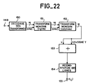
- FIG. 22 represents the block diagram of an exemplary embodiment of a device for decoding images which have been coded by a two-dimensional direct cosine transformation.
- This device comprises in series: a device 150 for decoding the values of the two-dimensional direct cosine transforms; two devices for calculating one-dimensional inverse cosine transforms 151 and 152; an adder 153; and a device 154 for reconstituting the image lines.
- An input terminal 149 receives blocks of 16 ⁇ 16 coded values representing blocks of 16 ⁇ 16 values of two-dimensional direct cosine transforms, by a coding which has been carried out, for example, according to the method described in: IEEE Transactions on Communications, VOL.COM-32, No. 3, March 1984, "Scene Adaptive Coder" by WEN-HSIUNG CHEN and William K. PRATT.
- the decoding device 150 decodes the coded values according to a method opposite to this coding method and which is described in the same document, and the device 150 supplies decoded values to a first input of the device 151.
- the decoding device 150 also provides a synchronization signal to a second input of the device 151, for each block of 16 ⁇ 16 decoded values which it supplies to it.
- the device 151 performs a one-dimensional cosine transformation in lines, successively on 16 sequences of 16 values, for each packet. It provides a first input to the device 152 with a packet consisting of 16 sequences of 16 values, accompanied by a synchronization signal applied to a second input to the device 152.
- the device 152 performs a reverse mono-dimensional cosine transformation in columns successively on 16 sequences of 16 values from the packet supplied by device 151.
- the device 152 has an output connected to a first input of the adder 153 and providing a binary word of 16 bits, of value Y, ten bits representing the whole part including the sign of Y and 6 bits representing the decimal part.
- a second input of the adder 153 receives a bit which is the sign bit of the value Y, denoted Sign (Y).
- the adder 153 adds the sign bit of Y to the 16 bits representing Y, giving the bit to be added, Sign (Y), a rank which corresponds to the most significant bit in the decimal part, i.e. the sixth row from the right.
- the adder 153 thus adds to Y a value equal to 0.5 when Y has a negative value and thus makes it possible to statistically improve the precision of the restitution of the luminance values, because a statistical study of the coding and decoding errors has shown that there is statistically a default error which can be reduced by adding to each decoded luminance value a correction value equal to 0.5 when the Y value is negative and equal to 0 when the Y value is positive.
- the adder 153 has an output providing a 16-bit binary word representing a luminance value, 10 bits representing the integer part and the sign, 6 bits representing the decimal part.
- the 2 most significant bits, and the bits of the decimal part allow to detecting and clipping the values of Y which are negative, or greater than 255.
- the luminance values being restored in blocks of 16 ⁇ 16 values corresponding to square blocks of 16 ⁇ 16 image points it is necessary to reconstruct a series of luminance values corresponding to the usual order of analysis of an image, that is to say corresponding to each point of a line successively, for each line successively.
- This role is fulfilled by the line rendering device 154, which restores the luminance values f (i, j) and then supplies them to an output terminal 155 of the decoding device.
- the invention can be applied in particular for coding and decoding television images in a digital video recorder.
Description
L'invention concerne les dispositifs de calcul de transformées cosinus, qui sont utilisés notamment pour réaliser le codage d'images afin de réduire la quantité des informations représentant ces images. Cette réduction d'informations permet de transmettre ou de stocker des images par des moyens ayant un débit d'informations limité.The invention relates to devices for calculating cosine transforms, which are used in particular for coding images in order to reduce the amount of information representing these images. This reduction in information makes it possible to transmit or store images by means having a limited rate of information.
Il est connu par exemple de l'article suivant publié dans la revue IEEE Transactions on Communications, Vol com 25 no9 septembre 1977 pages 1004-1009, New-York, US; WACHEN et al ayant pour titre "A fast computational algorithm for the discrete cosines transform" ou encore dans l'article IEEE Transactions on Computers Vol. C-31 septembre 1982 pages 899-906, IEEE, New-York US FA KAMANGAR et al ayant pour titre "Fast algorithms for the 2D discrete cosine transform"; de coder des valeurs représentatives de la luminance et de la couleur des points d'une image par une transformation dite transformation cosinus bi-dimensionnelle. Ce codage fait correspondre une matrice de N x N valeurs, dites transformées cosinus directes, à une matrice de N x N valeurs représentatives d'un bloc de N x N points de l'image à coder. Cette image est découpée généralement en portions carrées constituées chacune d'un bloc de N x N points. Une pondération des valeurs transformées permet de réduire la quantité des informations représentatives d'une image. Le décodage consiste à appliquer une pondération inverse puis une transformation cosinus inverse qui fait correspondre une matrice de N x N valeurs transformées inverses à une matrice de N x N transformées directes. Comme le codage, le décodage est réalisé par blocs de N x N points d'images.It is known, for example, the following article published in IEEE Transactions on Communications, Vol com 25 No. 9 September 1977 from 1004 to 1009 pages, New York, US; WACHEN et al, entitled "A fast computational algorithm for the discrete cosines transform" or in the article IEEE Transactions on Computers Vol. C-September 31, 1982 pages 899-906, IEEE, New-York US FA KAMANGAR et al entitled "Fast algorithms for the 2D discrete cosine transform"; to code values representative of the luminance and of the color of the points of an image by a transformation called bi-dimensional cosine transformation. This coding makes a matrix of N x N values, called direct cosine transforms, correspond to a matrix of N x N values representative of a block of N x N points of the image to be coded. This image is generally divided into square portions each consisting of a block of N x N points. A weighting of the transformed values makes it possible to reduce the amount of information representative of an image. Decoding consists in applying an inverse weighting then an inverse cosine transformation which makes correspond a matrix of N x N inverse transformed values to a matrix of N x N direct transformed. Like coding, decoding is carried out by blocks of N x N picture points.
Si les valeurs représentatives des points d'un bloc sont f(i,j) pour i = 0 à N - 1 et j = 0 à N - 1, les valeurs des transformées cosinus directes bi-dimensionnelles sont données par les formules suivantes :
pour u = 0 à N - 1
et v = 0 à N - 1,
for u = 0 to N - 1
and v = 0 to N - 1,
Les valeurs transformées inverses sont fournies par la transformation cosinus inverse bi-dimensionnelle en appliquant la formule suivante :
Cette transformation cosinus bi-dimensionnelle peut être décomposée en deux transformations cosinus mono-dimensionnelles et le calcul des transformées bi-dimensionnelles peut être réalisé au moyen de deux dispositifs de calcul de transformées mono-dimensionnelles, reliés en cascade.This two-dimensional cosine transformation can be broken down into two one-dimensional cosine transformations and the calculation of the two-dimensional transforms can be carried out by means of two devices for calculating one-dimensional transforms, connected in cascade.
La transformation cosinus mono-dimensionnelle est réalisée selon les formules suivantes:
La transformation cosinus inverse mono-dimensionnelle est réalisée selon les formules suivantes :
Le codage d'une image par la transformation cosinus suivie d'une pondération permet de réaliser une forte réduction de la quantité d'informations à transmettre mais a pour inconvénient de nécessiter de très nombreux calculs. Cette quantité de calculs est coûteuse en matériel et en temps de calcul. Elle rend très difficile l'application de la transformation cosinus au codage et au décodage d'une suite d'images vidéo à la fréquence habituelle, cinquante trames par seconde dans les standards européens.The coding of an image by the cosine transformation followed by a weighting makes it possible to achieve a large reduction in the amount of information to be transmitted but has the drawback of requiring very many calculations. This quantity of calculations is costly in material and in calculation time. It makes it very difficult to apply the cosine transformation to the coding and decoding of a series of video images at the usual frequency, fifty frames per second in European standards.
On connaît des algorithmes rapides permettant de réaliser une transformation cosinus avec un nombre de multiplications et d'additions élémentaires relativement réduit, notamment l'algorithme de Chen et al qui est décrit notamment par R.A. Duryea dans l'article intitulé "Performance of a source/channel encoded imagery transmission system" Thesis AFIT/GE/EE/79D-12, Air Force Institute of Technology, OHIO décembre 1979. Il est déduit de la formule (3) précitée en mettant à profit les relations mathématiques existant entre les coefficients aik. Cet algorithme permet d'effectuer une transformation cosinus mono-dimensionnelle des valeurs numériques représentatives de 16 points d'image, par 44 multiplications et 74 additions. Il a été mis en oeuvre dans des dispositifs de calcul de transformées cosinus mono-dimensionnelles, mais cet algorithme présente l'inconvénient d'avoir une structure irrégulière se traduisant par une certaine complexité du dispositif de mise en oeuvre.Fast algorithms are known which make it possible to carry out a cosine transformation with a number of multiplications and additions relatively small elementaries, notably the algorithm of Chen et al which is described in particular by RA Duryea in the article entitled "Performance of a source / channel encoded imagery transmission system" Thesis AFIT / GE / EE / 79D-12, Air Force Institute of Technology, OHIO December 1979. It is deduced from the above formula (3) by taking advantage of the mathematical relationships existing between the coefficients a ik . This algorithm makes it possible to carry out a mono-dimensional cosine transformation of the numerical values representative of 16 image points, by 44 multiplications and 74 additions. It has been implemented in devices for calculating one-dimensional cosine transforms, but this algorithm has the drawback of having an irregular structure resulting in a certain complexity of the implementation device.
Le but de l'invention est de réaliser, pour un faible coût, un dispositif de calcul de transformées cosinus directes mono-dimensionnelles et un dispositif de calcul de transformées cosinus inverses mono-dimensionnelles ayant une structure plus simple que les dispositifs mettant en oeuvre l'algorithme de Chen et al, pour transformer des suites de 16 valeurs. Le but de l'invention est aussi de réaliser un dispositif de codage et un dispositif de décodage appliquant en temps réel la transformation cosinus bi-dimensionnelle à des images vidéo répondant aux standards de la télévision classique.The object of the invention is to produce, for a low cost, a device for calculating direct cosine transforms mono-dimensional and a device for calculating inverse cosine transforms mono-dimensional having a simpler structure than the devices implementing the 'algorithm of Chen et al, to transform sequences of 16 values. The object of the invention is also to provide a coding device and a decoding device applying in real time the two-dimensional cosine transformation to video images meeting the standards of conventional television.
L'invention a notamment pour objet un dispositif de calcul de transformées cosinus directes mono-dimensionnelles et un dispositif de calcul de transformées cosinus inverses mono-dimensionnelles mettant en oeuvre deux algorithmes dérivés d'algorithmes connus, décrits par Beyeong Gi Lee dans "A new algorithm to compute the discrete cosine transform" - IEEE Trans. on Acoustic, Speech and Signal Processing. Vol.ASSP-32, no6, pp1243-1245, December 1984. Ces algorithmes de Beyeong Gi Lee sont modifiés pour permettre leur mise en oeuvre par des dispositifs de calcul de transformées constitués essentiellement d'un petit nombre de mémoires vives et d'un petit nombre de dispositifs de calcul élémentaires réalisables au moyen de circuits intégrés disponibles dans le commerce, et pouvant fonctionner à un rythme égal au rythme d'analyse des points d'image dans les standards de la télévision classique.The subject of the invention is in particular a device for calculating direct mono-dimensional cosine transforms and a device for calculating inverse mono-dimensional cosine transforms implementing two algorithms derived from known algorithms, described by Beyeong Gi Lee in "A new algorithm to compute the discrete cosine transform "- IEEE Trans. on Acoustic, Speech and Signal Processing. Vol.ASSP-32, No. 6, pp1243-1245, December 1984. These algorithms Beyeong Gi Lee are modified to allow their implementation by devices for calculating transformed consisting essentially of a small number of RAMs and '' a small number of elementary computing devices achievable by means of commercially available integrated circuits, and capable of operating at a rate equal to the rate of analysis of the image points in the standards of conventional television.
L'invention a aussi pour objet un dispositif de codage et un dispositif de décodage d'images par la transformation cosinus bi-dimensionnelle, comportant deux dispositifs de calcul de transformées cosinus mono-dimensionnelles.A subject of the invention is also a coding device and a device for decoding images by the two-dimensional cosine transformation, comprising two devices for calculating one-dimensional cosine transforms.
Selon l'invention, un dispositif de calcul de transformées cosinus directes mono-dimensionnelles, pour transformer des suites de 16 valeurs, est caractérisé en ce qu'il comporte :
- une mémoire d'entrée, pour stocker une suite de 16 valeurs à transformer ;
- des premiers moyens de calcul comprenant un circuit additionneur et un circuit soustracteur couplé à une première entrée d'opérande d'un circuit multiplicateur par l'intermédiaire d'un registre à décalage à D₂ positions de décalage pour calculer, à partir de deux valeurs binaires d'opérande A et B et d'une valeur de coefficient

- des premiers moyens de stockage de valeurs intermédiaires, couplés aux premiers moyens de calcul, pour leur fournir comme opérandes des valeurs qu'ils ont calculées antérieurement ;
- des seconds moyens de calcul pour calculer une valeur de la forme E + G, où E et G sont deux opérandes appliqués consécutivement à une entrée de ces seconds moyens de calcul ;
- des seconds moyens de stockage de valeurs intermédiaires, couplés aux seconds moyens de calcul pour leur fournir comme opérandes des valeurs qu'ils ont calculées antérieurement, et couplés à une borne de sortie du dispositif de calcul de transformées, pour lui fournir une suite de 16 valeurs transformées ;
- des moyens de commande commandant la mémoire d'entrée, les premiers et les seconds moyens de stockage de valeurs intermédiaires, les premiers et les seconds moyens de calcul, par des signaux de commande ayant un rythme double de celui des valeurs à transformer et ayant une période correspondant à une suite de 16 valeurs à transformer, et par un signal d'horloge ayant un rythme double de celui des valeurs à transformer.
- an input memory, for storing a series of 16 values to be transformed;
- first calculation means comprising an adder circuit and a subtractor circuit coupled to a first operand input of a multiplier circuit by means of a shift register with D₂ shift positions for calculating, from two binary values of operand A and B and a coefficient value
- first means for storing intermediate values, coupled to the first calculation means, to supply them as operands with values that they have previously calculated;
- second calculation means for calculating a value of the form E + G, where E and G are two operands applied consecutively to an input of these second calculation means;
- second means for storing intermediate values, coupled to second calculation means to supply them as operands with values that they have previously calculated, and coupled to an output terminal of the transform calculation device, to provide it with a series of 16 transformed values;
- control means controlling the input memory, the first and second means for storing intermediate values, the first and second calculation means, by control signals having a rhythm twice that of the values to be transformed and having a period corresponding to a series of 16 values to be transformed, and by a clock signal having a rhythm twice that of the values to be transformed.
Selon l'invention, un dispositif de calcul de transformées cosinus inverses mono-dimensionnelles, pour transformer une suite de 16 valeurs transformées directes, est caractérisé en ce qu'il comporte :
- des premiers moyens de calcul fournissant une valeur de la forme E + G, où E et G sont deux opérandes appliqués consécutivement à une entrée de ces premiers moyens de calcul ;
- des premiers moyens de stockage de valeurs intermédiaires, couplés à une entrée et à une sortie des premiers moyens de calcul pour leur fournir comme opérandes des valeurs qu'ils ont calculées antérieurement, et couplés à une borne d'entrée recevant les valeurs à transformer ;
- des seconds moyens de calcul pour calculer deux valeurs binaire de la forme A + D.B et A - D.B, où A et B sont deux opérandes respectivement appliqués à deux entrées de ces seconds moyens de calcul, où D est un coefficient prédéterminé ; et où la valeur DB est obtenue par décalage dans un registre à décalage à D₂ positions de la valeur binaire B et multiplication de la valeur binaire décalée par un nombre D₁ par un circuit multiplicateur tel que

- des seconds moyens de stockage de valeurs intermédiaires, couplés aux seconds moyens de calcul pour leur fournir comme opérandes des valeurs qu'ils ont calculées antérieurement, et couplés à une borne de sortie du dispositif de calcul de transformées inverses, pour fournir à cette borne de sortie une suite de 16 valeurs transformées inverses ;
- des moyens de commande commandant les premiers et les seconds moyens de stockage de valeurs intermédiaires, et les premiers et les seconds moyens de calcul, par des signaux de commande ayant un rythme double de celui des valeurs à transformer et ayant une période correspondant à une suite de 16 valeurs à transformer, et par un signal d'horloge ayant un rythme double de celui des valeurs à transformer.
- first calculation means providing a value of the form E + G, where E and G are two operands applied consecutively to an input of these first calculation means;
- first means for storing intermediate values, coupled to an input and an output of the first calculation means to supply them as operands with values that they have previously calculated, and coupled to an input terminal receiving the values to be transformed;
- second calculation means for calculating two binary values of the form A + DB and A - DB, where A and B are two operands respectively applied to two inputs of these second calculation means, where D is a predetermined coefficient; and where the value DB is obtained by shifting in a shift register at D₂ positions of the binary value B and multiplication of the binary value shifted by a number D₁ by a multiplier circuit such that
- second means for storing intermediate values, coupled to the second calculation means for supplying them as operands with values that they have previously calculated, and coupled to an output terminal of the inverse transform calculation device, for supplying this terminal with output a sequence of 16 inverse transformed values;
- control means controlling the first and second means for storing intermediate values, and the first and second calculation means, by control signals having a rhythm twice that of the values to be transformed and having a period corresponding to a sequence of 16 values to be transformed, and by a clock signal having a rhythm twice that of the values to be transformed.
L'invention sera mieux comprise et d'autres détails apparaîtront à l'aide de la description ci-dessous et des figures l'accompagnant :
- la figure 1 représente un diagramme de calcul des transformées cosinus mono-dimensionnelles directes pour une suite de 16 valeurs, selon l'algorithme de Beyeong Gi Lee ;
- les figures 2 et 3 représentent des opérations élémentaires qui sont extraites du diagramme de la figure 1 ;
- la figure 4 représente un diagramme de calcul des transformées cosinus mono-dimensionnelles directes pour une suite de 16 valeurs, selon l'algorithme de Beyeong Gi Lee modifié ;
- la figure 5 représente un schéma synoptique d'un exemple de réalisation d'un dispositif de calcul de transformées cosinus directes mono-dimensionnelles pour des blocs de 16 valeurs, selon l'invention ;
- la figure 6 représente un diagramme illustrant le fonctionnement d'une partie de cet exemple de réalisation ;
- la figure 7 représente un schéma synoptique plus détaillé de cet exemple de réalisation ;
- les figures 8, 9, 10 représentent des schémas synoptiques plus détaillés de certaines parties de cet exemple de réalisation ;
- la figure 11 représente le schéma synoptique d'un exemple de réalisation d'un dispositif de codage d'images comportant deux dispositifs de calcul de transformées cosinus mono-dimensionnelles selon l'invention ;
- la figure 12 représente le schéma synoptique d'un exemple de réalisation d'une variante de ce dispositif de codage d'images ;
- les figures 13 et 14 représentent le schéma synoptique d'exemples de réalisation de deux variantes du dispositif de calcul de transformées cosinus directes mono-dimensionnelles pour des blocs de 16 valeurs, selon l'invention ;
- la figure 15 représente un diagramme de calcul des transformées cosinus mono-dimensionnelles inverses pour une suite de 16 valeurs, selon l'algorithme de Beyeong Gi Lee ;
- la figure 16 représente un diagramme de calcul des transformées cosinus mono-dimensionnelles inverses pour une suite de 16 valeurs, selon l'algorithme de Beyeong Gi Lee, modifié ;
- la figure 17 représente une opération élémentaire extraite du diagramme de la figure 15 ;
- la figure 18 représente un schéma synoptique d'un exemple de réalisation d'un dispositif de calcul de transformées cosinus inverses mono-dimensionnelles pour des blocs de 16 valeurs, selon l'invention ;
- les figures 19 à 21 représentent des schémas synoptiques plus détaillés de certaines parties de cet exemple de réalisation ;
- la figure 22 représente le schéma synoptique d'un exemple de réalisation d'un dispositif de décodage d'image comportant deux dispositifs de calcul de transformées cosinus mono-dimensionnelles selon l'invention.
- FIG. 1 represents a diagram for calculating direct mono-dimensional cosine transforms for a sequence of 16 values, according to the algorithm of Beyeong Gi Lee;
- Figures 2 and 3 represent elementary operations which are extracted from the diagram of Figure 1;
- FIG. 4 represents a diagram for calculating the direct mono-dimensional cosine transforms for a sequence of 16 values, according to the modified Beyeong Gi Lee algorithm;
- FIG. 5 represents a block diagram of an exemplary embodiment of a device for calculating one-dimensional direct cosine transforms for blocks of 16 values, according to the invention;
- FIG. 6 represents a diagram illustrating the operation of part of this exemplary embodiment;
- FIG. 7 represents a more detailed block diagram of this exemplary embodiment;
- Figures 8, 9, 10 show more detailed block diagrams of certain parts of this embodiment;
- FIG. 11 represents the block diagram of an exemplary embodiment of an image coding device comprising two devices for calculating mono-dimensional cosine transforms according to the invention;
- FIG. 12 represents the block diagram of an exemplary embodiment of a variant of this image coding device;
- Figures 13 and 14 show the block diagram of exemplary embodiments of two variants of the device for calculating direct cosine transforms mono-dimensional for blocks of 16 values, according to the invention;
- FIG. 15 represents a diagram for calculating the inverse mono-dimensional cosine transforms for a sequence of 16 values, according to the algorithm of Beyeong Gi Lee;
- FIG. 16 represents a diagram for calculating the inverse mono-dimensional cosine transforms for a sequence of 16 values, according to the modified Beyeong Gi Lee algorithm;
- FIG. 17 represents an elementary operation extracted from the diagram of FIG. 15;
- FIG. 18 represents a block diagram of an exemplary embodiment of a device for calculating one-dimensional inverse cosine transforms for blocks of 16 values, according to the invention;
- FIGS. 19 to 21 represent more detailed block diagrams of certain parts of this exemplary embodiment;
- FIG. 22 represents the block diagram of an exemplary embodiment of an image decoding device comprising two devices for calculating one-dimensional cosine transforms according to the invention.
La figure 1 représente la répartition dans le temps de toutes les opérations de calcul réalisées selon l'algorithme de Beyeong Gi Lee. Ces opérations de calcul fournissent 16 valeurs Fʹ(0), Fʹ(1), ... , Fʹ(15) qui sont égales, à un facteur près, aux 16 valeurs transformées F(0), F(1), ... , F(15) de 16 valeurs à transformer : f(0), f(15), f(7), f(8), f(3), f(12), f(4), f(11), f(1), f(14), f(6), f(9), f(2), f(13), f(5), f(10). Ce diagramme de calcul applique la formule (3), sans tenir compte des facteurs ![]()

![]()
Il apparaîtra dans la suite que la réalisation d'un dispositif de codage par transformation bi-dimensionnelle est plus simple si ces facteurs constants n'interviennent pas au cours du calcul mais seulement à la fin du calcul des transformées.It will appear hereinafter that the realization of a coding device by two-dimensional transformation is simpler if these constant factors do not intervene during the calculation but only at the end of the calculation of the transforms.
Les facteurs![]()
sont des constantes dont il sera tenu compte dans une étape ultérieure du calcul. Par la suite, on appellera valeurs transformées les valeurs Fʹ(0), ... , Fʹ(15) fournies par l'application de ce diagramme de calcul, bien qu'elles diffèrent des valeurs théoriques F(0), ... , F(15) données par la formule (3).Factors ![]()
are constants which will be taken into account in a later stage of the calculation. Thereafter, the values Fʹ (0), ..., Fʹ (15) provided by the application of this calculation diagram will be called transformed values, although they differ from the theoretical values F (0), ... , F (15) given by formula (3).
Ce diagramme comporte deux axes des temps : un axe horizontal orienté de gauche à droite et un axe vertical orienté de haut en bas, qui définissent l'ordre des opérations. Les 16 valeurs à transformer f(0), f(15), ... , f(10) sont disponibles successivement. Si, par exemple, elles représentent la luminance d'un bloc linéaire de 16 points d'une image, elles sont disponibles au rythme de l'échantillonnage de ces points d'image. Ces valeurs sont obtenues dans l'ordre (f0), f(1), ... , f(15) lors de l'échantillonnage. Elles sont mises ensuite dans l'ordre f(0), f(15), f(7), ... , f(10) pour pouvoir appliquer l'algorithme. Chaque valeur à transformer, chaque valeur intermédiaire, et chaque valeur transformée, est représentée par un point. Les opérations permettant d'obtenir les valeurs intermédiaires et les valeurs transformées sont représentées par des traits continus ou en pointillés. La convergence de deux traits continus symbolise une addition. La convergence d'un trait continu et d'un trait discontinu symbolise une soustraction. Un trait horizontal surmonté d'une valeur numérique symbolise une multiplication par cette valeur numérique, l'absence de valeur numérique symbolisant une transmission avec un coefficient 1.This diagram has two time axes: a horizontal axis oriented from left to right and a vertical axis oriented from top to bottom, which define the order of operations. The 16 values to transform f (0), f (15), ..., f (10) are available successively. If, for example, they represent the luminance of a linear block of 16 points of an image, they are available at the rate of sampling of these image points. These values are obtained in order (f0), f (1), ..., f (15) during sampling. They are then put in the order f (0), f (15), f (7), ..., f (10) to be able to apply the algorithm. Each value to be transformed, each intermediate value, and each value transformed, is represented by a point. The operations making it possible to obtain the intermediate values and the transformed values are represented by solid or dotted lines. The convergence of two continuous lines symbolizes an addition. The convergence of a continuous line and a broken line symbolizes a subtraction. A horizontal line surmounted by a numerical value symbolizes a multiplication by this numerical value, the absence of a numerical value symbolizing a transmission with a
Les figures 2 et 3 sont des extraits de la figure 1, donnant des exemples d'opérations symbolisées sur cette figure 1. La figure 2 représente un extrait de la première ligne de calcul, correspondant à la valeur à transformer f(0), et de la neuvième ligne de calcul correspondant à la valeur à transformer f(15). Sur la ligne correspondant à f(0), la première valeur intermédiaire est égale à la somme de f(0) et de f(15) car le point représentant cette première valeur intermédiaire est relié par un trait continu au point représentant la valeur à transformer f(0) et par un trait continu à la valeur représentant f(15). La seconde valeur intermédiaire est, elle aussi, égale à f(0) + f(15) car elle est reliée par un trait continu non surmonté d'une valeur numérique, à la première valeur intermédiaire.FIGS. 2 and 3 are extracts from FIG. 1, giving examples of operations symbolized in this FIG. 1. FIG. 2 represents an extract from the first calculation line, corresponding to the value to be transformed f (0), and of the ninth calculation line corresponding to the value to be transformed f (15). On the line corresponding to f (0), the first intermediate value is equal to the sum of f (0) and f (15) because the point representing this first intermediate value is connected by a solid line to the point representing the value at transform f (0) and by a continuous line to the value representing f (15). The second intermediate value is also equal to f (0) + f (15) because it is connected by a solid line not surmounted by a numerical value, to the first intermediate value.
Sur la ligne de calcul correspondant à f(15), la première valeur intermédiaire est égale à f(0) - f(15) car le point la représentant est relié par un trait en pointillés au point représentant la valeur à transformer f(15), et par un trait continu à la valeur à transformer f(0). La seconde valeur intermédiaire sur la ligne correspondant à f(15) est égale à
car elle est reliée par un trait continu surmonté de la valeur
au point représentant la seconde valeur intermédiaire, sur la ligne correspondant à f(15).On the calculation line corresponding to f (15), the first intermediate value is equal to f (0) - f (15) because the point representing it is linked by a dotted line to the point representing the value to be transformed f (15 ), and by a continuous line to the value to transform f (0). The second intermediate value on the line corresponding to f (15) is equal to
because it is connected by a solid line surmounted by the value
at the point representing the second intermediate value, on the line corresponding to f (15).
La figure 3 représente un extrait de la figure 1 correspondant à une partie des lignes de calcul fournissant les valeurs transformées Fʹ(4) et Fʹ(12). Seules les trois dernières valeurs intermédiaires de ces lignes sont représentées. Les calculs sont considérés à partir d'une première valeur intermédiaire g₁ et d'une première valeur intermédiaire g₂ respectivement. Sur la ligne correspondant à Fʹ(4) la seconde valeur intermédiaire est égale à g₁ + g₂ car elle est reliée par des traits continus aux valeurs intermédiaires g₁ et g₂ . La troisième valeur intermédiaire sur cette même ligne, et la valeur transformée Fʹ(4), sont égales à g₁ + g₂ car le calcul se réduit simplement à une transmission de la seconde valeur intermédiaire, sans retard. Sur la ligne correspondant à Fʹ(12), la seconde valeur intermédiaire, la troisième valeur intermédiaire, et la valeur transformée Fʹ(12) sont égales à g₂ car les calculs se réduisent à une transmission, sans retard.FIG. 3 represents an extract from FIG. 1 corresponding to a part of the calculation lines providing the transformed values Fʹ (4) and Fʹ (12). Only the last three intermediate values of these lines are shown. The calculations are considered from a first intermediate value g₁ and a first intermediate value g₂ respectively. On the line corresponding to Fʹ (4) the second intermediate value is equal to g₁ + g₂ because it is connected by solid lines to the intermediate values g₁ and g₂. The third intermediate value on this same line, and the transformed value Fʹ (4), are equal to g₁ + g₂ because the calculation is reduced simply to a transmission of the second intermediate value, without delay. On the line corresponding to Fʹ (12), the second intermediate value, the third intermediate value, and the transformed value Fʹ (12) are equal to g₂ because the calculations are reduced to a transmission, without delay.
L'ensemble des calculs représenté sur la figure 1 peut être réalisé par 32 multiplications et 81 additions. Sur le diagramme de la figure 1, les colonnes de valeurs séparent des colonnes d'opérations. L'observation de ce diagramme montre que la succession d'opérations à l'intérieur d'une colonne est différente dans chacune des colonnes d'opérations. La mise en oeuvre de cet algorithme nécessite donc une séquence d'opérations différente dans chacune des colonnes d'opérations, ce qui complique la réalisation du dispositif de mise en oeuvre.All the calculations shown in Figure 1 can be performed by 32 multiplications and 81 additions. In the diagram in Figure 1, the columns of values separate columns of operations. The observation of this diagram shows that the succession of operations inside a column is different in each of the columns of operations. The implementation of this algorithm therefore requires a different sequence of operations in each of the columns of operations, which complicates the implementation of the implementation device.
Dans le but de simplifier la réalisation du dispositif de mise en oeuvre, l'algorithme de Beyeong Gi Lee est modifié conformément à la figure 4. L'ordre des valeurs à transformer est modifié : f(0), f(15), f(7), f(8), f(3), f(12), f(4), f(11), f(1), f(14), f(6), f(9), f(2), f(13), f(5), f(10). Les lignes de points représentant les valeurs intermédiaires sont permutées de la même façon que les valeurs à transformer. Les liaisons entre les points représentant les valeurs à transformer, les valeurs intermédiaires, et les valeurs transformées sont maintenues au cours de ces permutations comme si les traits représentant ces liaisons étaient des fils élastiques.In order to simplify the implementation of the implementation device, the Beyeong Gi Lee algorithm is modified in accordance with Figure 4. The order of the values to be transformed is modified: f (0), f (15), f (7), f (8), f (3), f (12), f (4), f (11), f (1), f (14), f (6), f (9), f (2), f (13), f (5), f (10). The lines of points representing the intermediate values are swapped in the same way as the values to be transformed. The connections between the points representing the values to be transformed, the intermediate values, and the transformed values are maintained during these permutations as if the lines representing these connections were elastic threads.
L'ordre des valeurs transformées obtenu est donc modifié aussi : Fʹ(0), Fʹ(1), Fʹ(2), Fʹ(3), ... , Fʹ(15). Il est à remarquer que les valeurs à transformer ne sont plus dans l'ordre des indices croissants mais, par contre, les valeurs transformées sont désormais dans l'ordre des indices croissants. La propriété la plus remarquable de ce diagramme modifié est qu'il comporte quatre colonnes de calculs COL 1, COL 2, COL 3, COL 4, qui sont identiques. D'autre part, chacune de ces colonnes de calcul est constituée de huit opérations telles que celle représentée sur la figure 2. Chacune de ces huit opérations permet d'obtenir une valeur de la forme A + B et une valeur de la forme (A - B) × D à partir d'un premier opérande de valeur A, d'un second opérande de valeur B, et d'un troisième opérande de valeur D qui est une constante prédéterminée.The order of the transformed values obtained is therefore also modified: Fʹ (0), Fʹ (1), Fʹ (2), Fʹ (3), ..., Fʹ (15). It should be noted that the values to be transformed are no longer in the order of increasing indices but, on the other hand, the transformed values are now in the order of increasing indices. The most remarkable property of this modified diagram is that it has four columns of
La structure très répétitive de ce diagramme de calcul modifié permet donc d'obtenir 64 valeurs intermédiaires correspondant aux quatre colonnes d'opérations identiques, COL 1 à COL 4, au moyen d'un seul dispositif de calcul ayant une première et une seconde entrée d'opérande recevant deux valeurs A et B respectivement, ayant une entrée de troisième opérande recevant une valeur D et ayant deux sorties fournissant respectivement deux valeurs A + B et (A - B) × D. Si un tel dispositif de calcul fournit des couples de valeurs à un rythme double du rythme auquel sont disponibles les valeurs à transformer, alors un seul dispositif de calcul permet d'obtenir les 64 valeurs intermédiaires pendant la durée correspondant à 16 valeurs à transformer. Il en résulte donc une structure très simple du dispositif de calcul des transformées.The very repetitive structure of this modified calculation diagram therefore makes it possible to obtain 64 intermediate values corresponding to the four columns of identical operations,
Les trois colonnes d'opérations situées à la droite du diagramme de calcul de la figure 4 comportent au total 17 additions. Certaines valeurs fournies par les 4 premières colonnes d'opérations sont transmises sans modification et sans retard pour constituer des valeurs transformées. C'est le cas des valeurs transformées : Fʹ(0), Fʹ(2), Fʹ(12), Fʹ(14), Fʹ(15).The three columns of operations to the right of the calculation diagram in Figure 4 have a total of 17 additions. Certain values provided by the first 4 columns of operations are transmitted without modification and without delay to constitute transformed values. This is the case of transformed values: Fʹ (0), Fʹ (2), Fʹ (12), Fʹ (14), Fʹ (15).
En outre, il est à remarquer que les autres valeurs transformées résultant de plusieurs additions situées dans les trois dernières colonnes d'opérations, peuvent être considérées comme résultant d'additions en chaîne, c'est-à-dire que le diagramme de calcul d'une telle valeur transformée comporte une ligne horizontale, indiquant la transmission d'une valeur intermédiaire obtenue précédemment sur la même ligne, et une ligne oblique indiquant l'addition d'une autre valeur intermédiaire obtenue sur une autre ligne.In addition, it should be noted that the other transformed values resulting from several additions located in the last three columns of operations, can be considered as resulting from chain additions, that is to say that the calculation diagram d such a transformed value comprises a horizontal line, indicating the transmission of an intermediate value obtained previously on the same line, and an oblique line indicating the addition of another intermediate value obtained on another line.
Par exemple la valeur transformée Fʹ(3) est obtenue à partir d'une valeur intermédiaire calculée sur la quatrième ligne du diagramme, ligne correspondant à Fʹ(4), à laquelle est additionnée tout d'abord une valeur intermédiaire calculée sur la ligne correspondant à Fʹ(7), puis à laquelle est additionnée une valeur intermédiaire calculée sur la ligne correspondant à la valeur transformée Fʹ(5). Ces opérations d'additions en chaîne permettent d'obtenir une valeur intermédiaire, ou une valeur de transformée, en fournissant pour chaque addition un seul opérande à un additionneur, dès lors que la chaîne d'additions a été initialisée, ce qui est plus rapide et plus simple à réaliser que de fournir deux opérandes à un additionneur. Par exemple, pour réaliser une chaîne d'additions, telle que G + H + I + J, la première addition G + H nécessite deux périodes de calcul pour charger consécutivement les valeurs G et H, mais toutes les autres additions ne nécessitent qu'une seule période de calcul pour charger un nouvel opérande.For example, the transformed value Fʹ (3) is obtained from an intermediate value calculated on the fourth line of the diagram, line corresponding to Fʹ (4), to which is first added an intermediate value calculated on the corresponding line to Fʹ (7), then to which is added an intermediate value calculated on the line corresponding to the transformed value Fʹ (5). These chain addition operations make it possible to obtain an intermediate value, or a transform value, by providing for each addition a single operand to an adder, as soon as the addition chain has been initialized, which is faster. and simpler to perform than supplying two operands to an adder. For example, to make a chain of additions, such as G + H + I + J, the first addition G + H requires two calculation periods to load the values G and H consecutively, but all the other additions only require a single calculation period to load a new operand.
Cette deuxième particularité de la structure du diagramme de calcul permet elle aussi de simplifier le dispositif de mise en oeuvre de l'algorithme. Si un dispositif de calcul réalise des additions en chaîne à un rythme égal à deux fois celui où les valeurs à transformer sont disponibles, il peut aisément réaliser les 17 additions figurant sur le diagramme et fournir en sortie les 16 valeurs transformées, pendant la durée correspondant à 16 valeurs à transformer. Un seul dispositif de calcul réalisant des additions en chaîne sera alors suffisant.This second peculiarity of the structure of the calculation diagram also makes it possible to simplify the device for implementing the algorithm. If a calculation device performs chain additions at a rate equal to twice that where the values to be transformed are available, it can easily carry out the 17 additions appearing on the diagram and provide the 16 transformed values as output, for the corresponding duration to 16 values to transform. A single calculation device carrying out chain additions will then be sufficient.
A part le dispositif de calcul réalisant des opérations du type de celle représentée sur la figure 2 et le dispositif de calcul des additions en chaîne, il est nécessaire de prévoir des mémoires pour le stockage des valeurs intermédiaires qui constituent alternativement les résultats fournis par les dispositifs de calcul et les valeurs des opérandes appliquées à ces dispositifs de calcul.Apart from the calculation device performing operations of the type shown in FIG. 2 and the chain addition calculation device, it is necessary to provide memories for the storage of intermediate values which alternately constitute the results provided by the devices and the values of the operands applied to these computing devices.
La figure 5 représente le schéma synoptique d'un exemple de réalisation d'un dispositif de calcul de transformées cosinus directes mono-dimensionnelles, selon l'invention. Cet exemple comporte : une borne d'entrée 1 recevant des suites de 16 valeurs numériques qui peuvent être des valeurs représentatives d'un bloc linéaire de 16 points images ou être 16 valeurs transformées cosinus directes mono-dimensionnelles fournies par un autre dispositif de calcul de transformées cosinus directes mono-dimensionnelles, deux dispositifs selon l'invention étant associés en série pour réaliser un dispositif de calcul de transformées cosinus directes bi-dimensionnelles ; une borne d'entrée 2 recevant un signal de synchronisation ; une mémoire d'entrée 3 ; des moyens de commande 5 ; des premiers et des seconds moyens de stockage de valeurs intermédiaires, 4 et 8 ; des premiers et des seconds moyens de calcul, 6 et 7 ; un dispositif de changement d'ordre 9 ; une borne de sortie 11 fournissant des suites de 16 valeurs transformées calculées selon le diagramme de calcul de la figure 14 ; et une borne de sortie 13 fournissant un signal de synchronisation.FIG. 5 represents the block diagram of an exemplary embodiment of a device for calculating one-dimensional direct cosine transforms, according to the invention. This example includes: an
La mémoire d'entrée 3 possède une entrée de données reliée à la borne d'entrée 1 pour recevoir chaque valeur à transformer, sous la forme d'un mot binaire de 16 bits, et possède deux sorties reliées respectivement à une première entrée d'opérande et à une seconde entrée d'opérande des moyens de calcul 6 pour lui fournir respectivement deux mots binaires de 16 bits. Les moyens 4 de stockage de valeurs intermédiaires possèdent une première et une seconde sortie reliées en parallèle avec les sorties de la mémoire d'entrée 3 à la première et à la seconde entrée d'opérande des moyens de calcul 6. Les sorties des moyens 4 et de la mémoire 3 peuvent prendre trois états dont un état à haute impédance permettant d'éviter les conflits entre ces sorties.The
Les moyens de calcul 6 possèdent une première sortie reliée à une première entrée de données des moyens 4 et à une première entrée de données des moyens 8 et fournissant un mot binaire de 16 bits. Les moyens de calcul 6 possèdent aussi une seconde sortie reliée à une seconde entrée de données des moyens 4 et à une seconde entrée de données des moyens 8 et leur fournissant un mot binaire de 16 bits. Les moyens 8 possèdent : une troisième entrée de données reliée à une sortie des seconds moyens de calcul 7 pour recevoir un mot binaire de 16 bits ; une première sortie reliée à une entrée d'opérande des moyens de calcul 7 pour leur fournir un mot binaire de 16 bits ; et une seconde sortie reliée à une entrée du dispositif 9 de changement d'ordre pour lui fournir un mot binaire de 16 bits. Le dispositif 9 possède une sortie reliée à la borne de sortie 11 de l'exemple de réalisation représenté, pour lui fournir un mot binaire de 16 bits constituant une valeur transformée.The calculation means 6 have a first output connected to a first data input of the
Les moyens de commande 5 sont reliés à la borne d'entrée 2 pour recevoir le signal de synchronisation. Dans cet exemple le dispositif étant destiné à faire partie d'un dispositif de codage par transformation cosinus bi-dimensionnelle, le signal de synchronisation correspond à 16 suites de 16 valeurs à transformer, c'est-à-dire à un bloc de 16 × 16 points d'image. Les moyens 5 possèdent une sortie reliée à la borne de sortie 13 pour fournir un signal de synchronisation correspondant à 16 suites de 16 valeurs transformées fournies par la borne de sortie 11. Ce signal de synchronisation permet de synchroniser un second dispositif de calcul de transformées cosinus directes mono-dimensionnelles ou bien un dispositif de codage et de transmission de valeurs transformées.The control means 5 are connected to the
Les moyens de commande 5 possèdent aussi d'autres sorties, reliées par des liaisons non représentées, à des entrées de commande de la mémoire d'entrée 3, des moyens 4 et 8 de stockage de valeurs intermédiaires, des moyens de calcul 6 et 7, et du dispositif de changement d'ordre 9. Ils fournissent un signal d'horloge dont le rythme est deux fois plus élevé que le rythme auquel les valeurs à transformer sont appliquées à la borne d'entrée 1. Ils fournissent des signaux de commande selon un cycle dont la durée est égale à 32 périodes d'horloge et correspond à 16 valeurs à transformer, pour commander les moyens de calcul 6 et 7, les moyens de stockage 4 et 8, et la mémoire d'entrée 3 ; et ils fournissent des signaux de commande pour commander le dispositif 9, selon un cycle dont la durée est de 512 périodes d'horloge, ce qui correspond à 16 × 16 valeurs à transformer.The control means 5 also have other outputs, connected by connections not shown, to control inputs of the
La mémoire d'entrée 3 a pour fonction de stocker une par une les valeurs à transformer et de les restituer deux par deux pour constituer les deux opérandes utilisés par les premiers moyens de calcul 6 pour réaliser les opérations représentées dans la première colonne COL 1 du diagramme de calcul de la figure 4. Les valeurs à tranformer sont appliquées dans l'ordre indiqué sur le diagramme de la figure 4 : f(0), f(15), f(7), f(8), ... , f(10), qui n'est pas l'ordre d'analyse des points d'image correspondant. Les moyens d'échantillonnage, de numérisation, et de changement d'ordre des valeurs f(0), f(1), ... , f(15) ne sont pas représentés. Ils sont du domaine de la technique classique.The
Les moyens 4 ont pour rôle de stocker deux par deux les valeurs intermédiaires fournies par les sorties des moyens de calcul 6 puis de les fournir aux deux entrées d'opérande des moyens de calcul 6 pour réaliser les opérations représentées dans la seconde colonne COL 2, la troisième colonne COL 3, et la quatrième colonne COL 4, des opérations représentées sur la figure 4. Les moyens de calcul 6 fournissent respectivement sur leurs deux sorties des valeurs de la forme A + B et (A - B) × D lorsque deux valeurs de la forme A et B ont été appliquées respectivement sur leurs deux entrées d'opérande. La valeur D du troisième opérande est une constante sélectionnée par un signal de commande fourni par les moyens 5.The role of the
Les moyens 8 ont pour rôle de stocker les couples de valeurs intermédiaires fournies par les deux sorties des moyens de calcul 6 puis de fournir ces valeurs individuellement soit à l'entrée des moyens de calcul 7 soit à l'entrée du dispositif de changement d'ordre 9. Les moyens 8 stockent aussi des valeurs intermédiaires fournies par les moyens de calcul 7 à la troisième entrée de données des moyens 8.The role of the
Le dispositif de changement d'ordre 9 réalise un changement d'ordre des valeurs transformées fournies par la seconde sortie des moyens 8 de stockage de valeurs intermédiaires. Le changement d'ordre dépend de l'utilisation ultérieure des valeurs transformées. Le dispositif 9 stocke 16 suites de 16 valeurs transformées, qui sont calculées ligne après ligne d'après le tableau suivant :

Si les valeurs transformées sont appliquées à un second dispositif de calcul de transformées cosinus directes mono-dimensionnelles, en vue d'obtenir des transformées cosinus directes bi-dimensionnelles, le changement d'ordre a deux buts :
- lire les valeurs de ce tableau, colonne par colonne,
- et lire les valeurs de chaque colonne dans l'ordre attendu par le second dispositif de calcul, c'est-à-dire l'ordre des valeurs à transformer indiqué sur le diagramme de la figure 4 : Fʹ⁰(0), Fʹ¹⁵(0), Fʹ⁷(0), Fʹ⁸(0), ... , Fʹ¹⁰(0), puis Fʹ⁰(1), Fʹ¹⁵(1), ... , Fʹ¹⁰(1), puis Fʹ⁰(2), ... etc. Le second dispositif de calcul de transformées a alors une mémoire identique à la mémoire d'entrée 3.
- read the values in this table, column by column,
- and read the values of each column in the order expected by the second calculation device, that is to say the order of the values to be transformed indicated on the diagram in FIG. 4: Fʹ⁰ (0), Fʹ¹⁵ (0 ), Fʹ⁷ (0), Fʹ⁸ (0), ..., Fʹ¹⁰ (0), then Fʹ⁰ (1), Fʹ¹⁵ (1), ..., Fʹ¹⁰ (1), then Fʹ⁰ (2), ... etc. The second transform calculation device then has a memory identical to the
input memory 3.
Dans le cas où cet exemple de réalisation constitue le second dispositif de calcul de transformées cosinus mono-dimensionnelles, sa borne de sortie 11 fournit des valeurs transformées Fʹ(u,v) dans un ordre adapté pour les traitements ultérieurs, généralement destinés à réduire la quantité d'informations représentant une image. Cet ordre adapté est en général l'ordre défini par la figure 6 et qui est dit ordre zig-zag. Cet ordre correspond à un classement des valeurs transformées selon les valeurs de u et v croissantes, ce qui correspond à des valeurs absolues statistiquement décroissantes pour les valeurs transformées.In the case where this exemplary embodiment constitutes the second device for calculating one-dimensional cosine transforms, its
Le choix du format des valeurs est particulièrement important pour la réalisation du dispositif selon l'invention. Les moyens de calcul 6 et 8 travaillent sur des valeurs ayant un format prédéterminé : 13 bits pour la partie entière et 3 bits pour la partie décimale. Ce format a été déterminé en calculant un majorant pour chacune des valeurs intermédiaires et pour chacune des valeurs transformées rencontrées sur le diagramme de la figure 4, en fonction d'un majorant des valeurs à transformer. Lorsque celles-ci sont constituées par des valeurs de luminance, elles sont codées sur 8 bits et sont comprises entre 0 et + 255. Les valeurs intermédiaires et les valeurs transformées ont alors pour majorants + 4080 et - 2778. Pour éviter tout débordement du format, ces valeurs de majorants conduisent à choisir un format de 13 bits pour la partie entière, parmi lesquels un bit dédié au signe. Comme, d'autre part, les circuits multiplicateurs disponibles dans le commerce traitent couramment des valeurs de 16 bits, un format de 3 bits pour la partie décimale a été choisi.The choice of the format of the values is particularly important for the production of the device according to the invention. The calculation means 6 and 8 work on values having a predetermined format: 13 bits for the integer part and 3 bits for the decimal part. This format was determined by calculating an upper bound for each of the intermediate values and for each of the transformed values encountered in the diagram in FIG. 4, as a function of a upper bound for the values to be transformed. When these consist of luminance values, they are coded on 8 bits and are between 0 and + 255. The intermediate values and the transformed values then have the upper bounds + 4080 and - 2778. To avoid any overflow of the format , these upper bound values lead to choosing a 13-bit format for the whole part, among which a bit dedicated to the sign. Since, on the other hand, commercially available multiplier circuits commonly process 16-bit values, a 3-bit format for the decimal part was chosen.
Un dispositif de calcul de transformées cosinus bi-dimensionnelles comporte, en série, deux dispositifs de calcul de transformées mono-dimensionnelles. Un premier dispositif reçoit des valeurs à transformer qui sont des valeurs de luminance comprises entre 0 et + 255 et qui sont représentées par 8 bits. Pour éviter tout débordement du format au cours des calculs, ces 8 bits constituent les 8 bits de plus faible poids parmi les 13 bits réservés à la partie entière des valeurs appliquées à la borne d'entrée 1.A device for calculating two-dimensional cosine transforms comprises, in series, two devices for calculating one-dimensional transforms. A first device receives values to be transformed which are luminance values between 0 and + 255 and which are represented by 8 bits. To avoid any overflow of the format during the calculations, these 8 bits constitute the 8 least significant bits among the 13 bits reserved for the integer part of the values applied to the
Un second dispositif, identique au premier, mis à part pour le fonctionnement du dispositif de changement d'ordre 9, reçoit des valeurs à transformer qui sont constituées par les transformées cosinus mono-dimensionnelles Fʹ(u), pour u = 1 à 15, fournies par la borne de sortie 11 du premier dispositif. Ces valeurs Fʹ(u) ont le format prédéterminé, comportant 13 bits pour la partie entière, dont le bit de signe, et 3 bits pour la partie décimale. Fʹ(0) est comprise entre 0 et + 4080 et Fʹ(u) pour u = 1 à 15 est comprise entre - 1442 et + 1442, sans tenir compte des coefficients ![]()
![]()
Ces valeurs ne sont pas dans la fourchette 0, + 255 considérée précédemment pour déterminer le format des valeurs dans l'ensemble du premier dispositif de calcul de transformées mono-dimensionnelles. Il est possible de ramener ces valeurs dans cette fourchette au moyen d'une division par 16. La valeur Fʹ(u) divisée par 16 est comprise alors dans la fourchette 0, + 255 et la valeur Fʹ(u) pour u = 1 à 15 est comprise entre - 127 et + 127, ce qui est équivalent pour le format, car il suffit alors de 8 bits dans les deux cas. Les valeurs fournies par le premier dispositif peuvent donc être ramenées dans une fourchette 0, + 255 ou - 127, + 127, pour éviter tout débordement des valeurs intermédiaires ou des valeurs transformées, au moyen d'un décalage de 4 bits à droite. La virgule reste devant les 3 bits de la partie décimale.These values are not in the
D'autre part, le format des valeurs à transformer défini précédemment pour le premier dispositif de calcul de transformées cosinus mono-dimensionnelles, ne comporte pas de partie décimale, autrement dit la virgule est fixée à droite du bit de plus faible poids. Quand une valeur Fʹ(u) comportant 3 bits de valeur décimale est appliquée à cette entrée, tout se passe comme si sa virgule était décalée de 3 bits à droite, autrement dit la valeur est multipliée par 8.On the other hand, the format of the values to be transformed defined previously for the first device for calculating one-dimensional cosine transforms, does not include a decimal part, in other words the comma is fixed to the right of the least significant bit. When a value Fʹ (u) comprising 3 bits of decimal value is applied to this entry, everything happens as if its comma were shifted by 3 bits to the right, in other words the value is multiplied by 8.
Compte tenu de ces deux remarques, le changement de format entre les deux dispositifs de calcul de transformées mono-dimensionnelles provoque donc une division par 2 de la valeur transmise. Cette division par 2 sera compensée par l'opération de normalisation, en même temps que seront pris en compte les coefficients
Cette opération de normalisation est réalisée après la seconde transformation directe mono-dimensionnelle.Given these two remarks, the change in format between the two devices for calculating one-dimensional transforms therefore causes the value transmitted to be divided by 2. This division by 2 will be compensated by the normalization operation, while the coefficients will be taken into account.
This normalization operation is carried out after the second direct one-dimensional transformation.
Ainsi dans les deux dispositifs de calcul de transformées mono-dimensionnelles les calculs sont réalisés avec un même format fixé. Ces calculs fournissent des résultats moins précis que des calculs avec virgule flottante, mais ils peuvent être réalisés au moyen de circuits beaucoup plus simples, plus rapides, moins chers, et plus faciles à intégrer.Thus in the two devices for calculating one-dimensional transforms the calculations are carried out with the same fixed format. These calculations provide less accurate results than floating point calculations, but they can be performed using much simpler, faster, cheaper, and easier to integrate circuits.
La figure 7 représente un schéma synoptique plus détaillé de l'exemple de réalisation représenté sur la figure 5. Les moyens de commande 5 sont constitués d'une horloge 25 de fréquence 22,5 MHz et d'un séquenceur 26. Dans cet exemple, une image est échantillonnée à une fréquence de 13,5 MHz mais les valeurs représentatives des points de cette image sont fournies au dispositif de calcul de transformées à une fréquence de 11,25 MHz car le temps de suppression entre les lignes d'image est récupéré. La fréquence de l'horloge 25 est le double de la fréquence à laquelle les valeurs à transformer sont apppliquées à la borne d'entrée 1. Une sortie de l'horloge 25 est reliée à une entrée du séquenceur 26. Le séquenceur 26 fournit des signaux de commande à l'ensemble du dispositif de calcul de transformées avec une période égale à 32 périodes de l'horloge 25. Il est synchronisé par le signal de synchronisation appliqué à la borne d'entrée 2 et indiquant le début de chaque bloc de 16 suites de 16 valeurs à transformer. Une sortie du séquenceur 26 fournit à la borne de sortie 13 un signal de synchronisation utilisable pour synchroniser un second dispositif de calcul de transformées cosinus directes mono-dimensionnelles. Une sortie multiple du séquenceur 26 fournit les signaux de commande nécessaires à tous les éléments constituant le dispositif de calcul de transformées.FIG. 7 represents a more detailed block diagram of the exemplary embodiment represented in FIG. 5. The control means 5 consist of a
La mémoire d'entrée 3 est constituée d'un registre 23 ayant une capacité d'un mot de 16 bits, et d'une mémoire vive 24 : ayant un port d'entrée de données relié à une sortie du registre 23, un premier et un second port de sortie de données constituant les deux sorties des moyens 3, un double port d'adressage relié à la sortie multiple des moyens de commande 5 et permettant de sélectionner respectivement les données sortant par les deux ports de sortie, et des entrées de commande reliées à la sortie multiple des moyens de commande 5, pour commander une lecture ou une écriture. Le registre 23 possède une entrée d'horloge reliée à la sortie multiple des moyens de commande 5 pour recevoir un signal de commande ayant une période égale à deux périodes d'horloge.The
La mémoire 24 est constituée de quatre circuits intégrés Am 29707 fabriqués par la société AMD. Elle permet une lecture simultanée de deux données sélectionnées respectivement par les deux ports d'adressage ou elle permet une lecture et une écriture simultanées à deux adresses sélectionnées respectivement par les deux ports d'adressage, ou encore elle permet deux lectures respectivement aux deux adresses sélectionnées par le double port d'adressage et simultanément une écriture à une adresse sélectionnée par l'un des ports d'adressage. Ce type de mémoire permet donc de lire et d'écrire simultanément à une même adresse. Il permet donc de stocker et de restituer simultanément un flot continu de valeurs à transformer appliquées à la borne d'entrée 1. La mémoire 24 stocke 16 valeurs à transformer, au rythme où elles sont disponibles sur la borne d'entrée 1, pendant la durée de 32 périodes d'horloge, et restitue 8 valeurs sur chacun des deux ports de sortie pendant la durée de huit périodes d'horloge.The
Ces 8 couples de valeurs sont utilisées par les moyens de calcul 6 pour calculer 16 premières valeurs intermédiaires, pendant 8 premières périodes d'horloge. Ensuite, pendant les 24 périodes d'horloge suivantes les moyens 6 reçoivent des valeurs intermédiaires fournies par les deux sorties des moyens 4 de stockage de valeurs intermédiaires. Pendant les 8 premières périodes d'horloge, dans chaque cycle de 32 périodes d'horloge, la mémoire 24 travaille simultanément en lecture et en écriture. Au cours de deux périodes d'horloge successives, parmi ces 8 premières périodes, une écriture et une lecture sont réalisées pendant une période d'horloge, à une première adresse, puis une lecture est réalisée à une seconde adresse pendant la période suivante. L'ordre de lecture des valeurs dans la mémoire 24 est fixé par l'algorithme de calcul, c'est : f(0), f(15), f(7), f(8), f(3), ... , f(10), comme indiqué sur la figure 4. L'écriture devant être réalisée à une même adresse que la lecture, mais à un rythme deux fois plus lent, les valeurs à transformer doivent donc être appliquées à la borne d'entrée 1 dans l'ordre : f(0), f(7), f(3), f(4), f(1), f(6), f(2), f(5) puis f(15), f(8), f(12), f(11), f(14), f(5), f(13), f(10).These 8 pairs of values are used by the calculation means 6 to calculate the first 16 intermediate values, during the first 8 clock periods. Then, during the following 24 clock periods, the
Les moyens 4 de stockage de valeurs intermédiaires sont constitués de deux mémoires distinctes, 21 et 22, stockant séparemment les premiers opérandes et les seconds opérandes qui sont à appliquer respectivement à la première et à la seconde entrée d'opérande des moyens de calcul 6. Chacune des mémoires 21 et 22 est constituée de quatre circuits intégrés Am 29707 et peut stocker 16 mots de 16 bits. Chacune de ces mémoires comporte un seul port d'entrée de données et un seul port de sortie. Les ports d'entrée de données des mémoires 21 et 22 constituent les deux entrées de données des moyens 4 et les ports de sortie constituent les deux sorties de données des moyens 4. Un port d'adressage de la mémoire 21 et un port d'adressage de la mémoire 22 sont reliés en parallèle à la sortie multiple des moyens de commande 5. Des entrées de commande de lecture et d'écriture des mémoires 21 et 22 sont reliées aussi à la sortie multiple des moyens de commande 5.The
Les moyens 4 sont constitués de deux mémoires distinctes 21 et 22 parce qu'ils doivent stocker simultanément deux valeurs qui sont fournies simultanément par les moyens de calcul 6 et fournir simultanément deux valeurs d'opérandes aux moyens de calcul 6. Il serait possible d'utiliser une seule mémoire à double port d'entrée et double port de sortie mais une mémoire de ce type n'a pas une rapidité suffisante dans cette application, en l'état actuel de la technologie.The
Les moyens de calcul 6 comportent un circuit de calcul 28 et deux multiplexeurs 34 et 35 à deux entrées et une sortie. Le circuit de calcul 28 possède deux bornes d'entrée 30 et 31 constituant la première et la seconde entrée d'opérande des moyens 6, une borne d'entrée de commande 29 reliée à la sortie multiple des moyens de commande 5, et deux bornes de sortie 32 et 33. La borne de sortie 32 est reliée à une première entrée du multiplexeur 34 et à une première entrée du multiplexeur 35. La borne de sortie 33 est reliée à une seconde entrée du multiplexeur 34 et à une seconde entrée du multiplexeur 35. La sortie du multiplexeur 34 et la sortie du multiplexeur 35 constituent respectivement la première et la seconde sortie des moyens 6. Le multiplexeur 34 et le multiplexeur 35 possèdent respectivement deux entrées de commande reliées en parallèle à la sortie multiple des moyens de commande 5.The calculation means 6 comprise a
Le circuit de calcul 28 fournit sur ses bornes de sortie 32 et 33 respectivement un premier résultat de la forme A + B et un second résultat de la forme (A - B) × D lorsqu'un premier opérande de la forme A et un second opérande de la forme B sont appliqués respectivement à la borne d'entrée 30 et à la borne d'entrée 31. Dans la suite des calculs, un résultat fourni par la borne 32 est utilisé soit comme premier opérande, appliqué à la borne d'entrée 30 après avoir été restitué par les moyens 4, soit comme second opérande appliqué à la borne d'entrée 31 après avoir été restitué par les moyens 4. Sur la figure 4, il apparaît que les valeurs intermédiaires situées sur les huit premières lignes dans les premières colonnes du diagramme de calcul sont du type A + B alors que les valeurs intermédiaires situées sur les huit dernières lignes sont du type (A - B) × D.The
Une valeur intermédiaire sur deux constitue ensuite le premier opérande et une valeur intermédiaire sur deux constitue ensuite un second opérande pour le circuit de calcul 28. Par conséquent, les résultats de la forme A + B doivent être stockés alternativement dans la mémoire 21 des premiers opérandes et alternativement dans la mémoire 22 des seconds opérandes. De même, pour les résultats de la forme (A - B) × D. Les moyens de commande 5 commandent donc les multiplexeurs 34 et 35 afin d'aiguiller les résultats fournis par le circuit de calcul 28 alternativement vers la mémoire 21 et vers la mémoire 22. Il est à noter que les multiplexeurs 34 et 35 ne seraient pas nécessaires si les moyens 4 étaient constitués d'une seule mémoire à double port d'entrée et à double port de sortie.An intermediate value out of two then constitutes the first operand and an intermediate value out of two then constitutes a second operand for the
Il est à remarquer aussi que dans le diagramme de calcul correspondant à l'algorithme de Beyeong Gi Lee modifié, représenté sur la figure 4, les valeurs intermédiaires successives de haut en bas sont alternativement du type A et B. La lecture de 16 opérandes dans les moyens 4 est donc bien répartie au cours des huit périodes d'horloge. Par contre, chaque opération réalisée par le circuit de calcul 28 fournit deux résultats qui sont simultanément des futurs opérandes du type A ou simultanément des futurs opérandes du type B. Pour éviter d'avoir à écrire simultanément deux résultats du type A dans la mémoire 21, et alternativement deux résultats du type B dans la mémoire 22, le circuit de calcul 28 retarde d'une période d'horloge le résultat de type A + B fourni par sa borne de sortie 32 afin de réaliser successivement l'écriture des deux résultats de même type, fournis par chaque opération du circuit de calcul 28.It should also be noted that in the calculation diagram corresponding to the modified Beyeong Gi Lee algorithm, represented in FIG. 4, the successive intermediate values from top to bottom are alternately of type A and B. The reading of 16 operands in the
Les moyens de calcul 8 comportent : quatre multiplexeurs, 36 à 39, équivalent chacun à un commutateur à un circuit et à deux positions ; deux mémoires vives, 40 et 41, à accès aléatoire, à double port d'adressage. Une première entrée du multiplexeur 36 et une première entrée du multiplexeur 37 constituent respectivement la première et la seconde entrée des moyens de calcul 8. Une seconde entrée du multiplexeur 36 et une seconde entrée du multiplexeur 37 sont reliées ensemble et constituent la troisième entrée des moyens de calcul 8. Une sortie du multiplexeur 36 et une sortie du multiplexeur 37 sont reliées respectivement à une entrée de données de la mémoire 40 et à une entrée de données de la mémoire 41. Une sortie de la mémoire 40 est reliée à une première entrée du multiplexeur 38 et à une première entrée du multiplexeur 39. Une sortie de la mémoire 41 est reliée à une seconde entrée du multiplexeur 38 et à une seconde entrée du multiplexeur 39. Une sortie du multiplexeur 38 et une sortie du multiplexeur 39 constituent respectivement la première et la seconde sortie des moyens de calcul 8.The calculation means 8 comprise: four multiplexers, 36 to 39, each equivalent to a switch with one circuit and with two positions; two random access memories, 40 and 41, random access, with double address port. A first input of the
Les multiplexeurs 36 à 39 possèdent chacun une entrée de commande reliée à une sortie des moyens de commande 5. Les mémoires 40 et 41 possèdent chacune deux ports d'adressage et une entrée de commande de lecture et d'écriture reliés à une sortie des moyens de commande 5. Chacune de ces mémoires est constituée de quatre circuits intégrés du type AM 29707 permettant de stocker 16 mots de 16 bits. La présence des deux mémoires 40 et 41 permet de stocker simultanément deux valeurs qui sont fournies simultanément par les deux sorties des moyens de calcul 6. Ainsi il est possible de stocker 16 valeurs en huit périodes d'horloge. Les deux sorties des moyens de stockage 8 permettent de fournir simultanément une valeur aux moyens de calcul 7 et une valeur au dispositif 9 de changement d'ordre. Ainsi le dispositif 9 peut recevoir 16 valeurs transformées pendant que les moyens de calcul 7 peuvent recevoir 16 valeurs intermédiaires, nécessaires au calcul de 17 additions, pendant la durée d'un cycle de 32 périodes d'horloge. L'aiguillage des valeurs reçues sur les entrées des moyens de stockage 8 et des valeurs à acheminer vers les sorties des moyens de stockage 8 est réalisé au moyen d'une suite de signaux de commande fournis par les moyens de commande 5 avec une période correspondant à 32 périodes d'horloge.The
Le dispositif 9 de changement d'ordre est constitué de deux registres 43 et 46 pouvant stocker une valeur de 16 bits, et deux mémoires vives à accès aléatoire, 44 et 45. Les registres 43 et 46 constituent respectivement un tampon d'entrée et un tampon de sortie reliés respectivement à l'entrée de données du dispositif 9 et à la borne de sortie 11. La sortie du registre 43 est reliée à une entrée de données de la mémoire 44 et à une entrée de données de la mémoire 45. Une entrée du registre 46 est reliée à la fois à une sortie de la mémoire 44 et à une sortie de la mémoire 45. La mémoire 44 et la mémoire 45 possèdent chacune une entrée d'adresse et des entrées de commande de lecture et d'écriture reliées respectivement à la sortie multiple des moyens de commande 5 par des liaisons non représentées sur la figure 7. Les mémoires 44 et 45 sont constituées chacune de 4 circuits intégrés Cy 7C122 fabriqués par Cypress et ayant une capacité de 256 × 4 bits.The
Les valeurs transformées sont stockées dans le dispositif 9 au fur et à mesure qu'elles sont disponibles, puis elles sont restituées par le dispositif 9 dans un ordre différent. Les moyens de commande 5 fournissent aux entrées d'adresses des mémoires 44 et 45 respectivement deux suites de valeurs d'adresse correspondant à ces deux ordres différents. Ils fournissent à l'une des mémoires, 44 ou 45, des signaux de commande d'écriture et ils fournissent à l'autre mémoire des signaux de commande de lecture, alternativement avec une période correspondant à 16 × 16 valeurs. Il est à remarquer que les valeurs transformées sont inscrites au rythme où elles sont disponibles, c'est-à-dire avec un rythme égal au rythme d'horloge, alors qu'elles sont restituées à un rythme égal au rythme où les valeurs à transformer sont appliquées à la borne d'entrée 1, c'est-à-dire avec un rythme deux fois plus faible que le rythme de l'horloge utilisée pour les calculs.The transformed values are stored in
La figure 8 représente un schéma synoptique d'un exemple de réalisation du circuit de calcul 28. Ce circuit de calcul comporte : huit registres pouvant stocker un mot de 16 bits, 50, 51, 54, 55, 57, 59, 60, 62 ; un additionneur 52 ; un soustracteur 53 ; un registre à barillet 58 ; une mémoire morte 56 ; un multiplicateur 61. Les bornes d'entrée 30 et 31 sont reliées respectivement à une entrée du registre 50 et à une entrée du registre 51 pour leur fournir un premier mot de 16 bits constituant un premier opérande A et un second mot de 16 bits constituant un second opérande B. La sortie du registre 50 est reliée à une première entrée de l'additionneur 52 et à une première entrée du soustracteur 53. La sortie du registre 51 est reliée à une seconde entrée de l'additionneur 52 et à une seconde entrée du soustracteur 53. La sortie de l'additionneur 52 est reliée à une entrée du registre 54. Une sortie du registre 54 est reliée à une entrée du registre 57. Une sortie du registre 57 est reliée à la borne de sortie 32 pour lui fournir un mot binaire de 16 bits représentant le résultat A + B.FIG. 8 represents a block diagram of an exemplary embodiment of the
La sortie du soustracteur 53 est reliée à une entrée du registre 55. Une sortie du registre 55 est reliée à une entrée de données du registre à barillet 58. Le registre à barillet 58 permet de décaler un mot de 16 bits, d'un nombre de bits variable déterminé par un mot binaire appliqué sur une entrée de commande. Ce mot binaire comporte deux bits et est fourni par une première sortie de la mémoire morte 56. Une sortie du registre à barillet 58 est reliée à une entrée du registre 59. Une sortie du registre 59 est reliée à une première entrée du multiplicateur 61. La mémoire morte 56 possède une seconde sortie reliée à une entrée du registre 60 pour lui fournir un mot de 16 bits, D₁ , et possède une entrée de commande reliée à la borne d'entrée 29 pour recevoir un mot binaire de 5 bits constituant une adresse pour cette mémoire morte 56. Une sortie du registre 60 est reliée à une seconde entrée du multiplicateur 61. Une sortie du multiplicateur 61 est reliée à une entrée du registre 62. Une sortie du registre 62 est reliée à la borne de sortie 33 pour lui fournir un mot binaire de 16 bits représentant le résultat (A - B) × D. Chacun des registres du circuit de calcul 28 possède une entrée d'horloge, non représentée, recevant le signal d'horloge produit par les moyens de commande 5.The output of the
La multiplication par la valeur prédéterminée D est réalisée, d'une part, au moyen du registre à barillet 58 produisant un décalage de 0, ou 1, ou 2, ou 3 bits, et, d'autre part, au moyen du multiplicateur 61. La mémoire morte 56 fournit d'une part un mot binaire D₂ de deux bits indiquant la valeur du décalage à réaliser par le registre à barillet 58 et, d'autre part, un mot binaire D₁ de 16 bits constituant un opérande appliqué à la seconde entrée du multiplicateur 61. La valeur de D est
Au cours des calculs représentés sur le diagramme de la figure 4, il est nécessaire de réaliser des multiplications par les coefficients suivants :

During the calculations represented on the diagram of figure 4, it is necessary to carry out multiplications by the following coefficients:
Il apparaît que les coefficients
sont compris entre 0,5 et 1. Leur représentation avec 0 bit pour la partie entière et 16 bits pour la partie décimale permet de conserver un seul et même format pour tous les calculs dans le dispositif de calcul de transformées. En effet, après la multiplication par une valeur représentée au moyen de 13 bits pour la partie entière et de 3 bits pour la partie décimale, le résultat a un format comportant 13 bits pour la partie entière et 19 bits pour la partie décimale, qui redonne un format de 13 bits pour la partie entière et 3 bits pour la partie décimale après avoir réalisée une troncature limitée aux 16 bits de poids les plus forts. Cette conservation du format de 13 bits pour la partie entière et de 3 bits pour la partie décimale, tout au long des calculs, permet de simplifier la gestion des additionneurs et des soustracteurs.It appears that the coefficients
are between 0.5 and 1. Their representation with 0 bit for the whole part and 16 bits for the decimal part makes it possible to keep one and the same format for all the calculations in the device for calculating transforms. Indeed, after multiplication by a value represented by means of 13 bits for the whole part and 3 bits for the decimal part, the result has a format comprising 13 bits for the whole part and 19 bits for the decimal part, which gives again a format of 13 bits for the whole part and 3 bits for the decimal part after having carried out a truncation limited to the 16 most significant bits. This conservation of the format of 13 bits for the whole part and 3 bits for the decimal part, throughout the calculations, makes it possible to simplify the management of adders and subtractors.
Par contre, les coefficients
sont supérieurs à 1. Ceci pose un problème car la multiplication d'un de ces coefficients par une valeur représentée dans un format comportant 3 bits pour la partie entière et 13 bits pour la partie décimale fournirait un résultat dont le format comporterait 16 bits pour la partie entière et 16 bits pour la partie décimale. Ce résultat aurait donc un format de 16 bits pour la partie entière et de 0 bits pour la partie décimale après une troncature limitée aux 16 bits de poids les plus forts. Il y aurait donc à la suite d'une telle multiplication, une perte du format comportant 13 bits pour la partie entière et 3 bits pour la partie décimale. Le passage du format comportant 13 bits pour la partie entière et 3 bits pour la partie décimale, au format comportant 16 bits pour la partie entière et 0 bit pour la partie décimale, provoquerait une perte de précision car le format comportant 13 bits pour la partie entière et 3 bits pour la partie décimale a été choisi pour pouvoir représenter le majorant de toutes les valeurs numériques rencontrées au cours du calcul, et donc un format de 16 bits pour la valeur entière est superflu.However, the coefficients
are greater than 1. This poses a problem because the multiplication of one of these coefficients by a value represented in a format comprising 3 bits for the integer part and 13 bits for the decimal part would provide a result whose format would comprise 16 bits for the integer part and 16 bits for the decimal part. This result would therefore have a format of 16 bits for the whole part and 0 bits for the decimal part after a truncation limited to the 16 most significant bits. There would therefore be following such a multiplication, a loss of format comprising 13 bits for the whole part and 3 bits for the decimal part. Switching from the format comprising 13 bits for the whole part and 3 bits for the decimal part, to the format comprising 16 bits for the whole part and 0 bits for the decimal part, would cause a loss of precision because the format comprising 13 bits for the integer part and 3 bits for the decimal part was chosen to be able to represent the upper bound of all the numerical values encountered during the calculation, and therefore a 16-bit format for the integer value is superfluous.
Compte tenu de ces remarques, une multiplication par les coefficients
est réalisée, d'une part, en effectuant un décalage de 1, 2, ou 3 bits à gauche sur la valeur à multiplier, pour multiplier cette valeur par 2, 4, ou 8, et, d'autre part, en multipliant la valeur ainsi obtenue par un coefficient
divisé au préalable par 2 ou 4, ou 8, respectivement.Given these remarks, a multiplication by the coefficients
is performed, on the one hand, by shifting 1, 2, or 3 bits to the left on the value to be multiplied, to multiply this value by 2, 4, or 8, and, on the other hand, by multiplying the value thus obtained by a coefficient
divided beforehand by 2 or 4, or 8, respectively.
Pour multiplier par les coefficients
le décalage réalisé est de 1 bit à gauche et les valeurs du coefficient appliqué à la seconde entrée du multiplicateur 61 sont
ou,
respectivement.To multiply by the coefficients
the offset achieved is 1 bit to the left and the values of the coefficient applied to the second input of the
or,
respectively.
Pour multiplier une valeur par![]()
un décalage de deux bits à gauche est réalisé par le registre à barillet 58 et une multiplication par
est réalisée par le multiplicateur 61.To multiply a value by ![]()
a shift of two bits to the left is carried out by the
is carried out by the
Pour multiplier une valeur par
un décalage de trois bits à gauche est réalisé par le registre à barillet 58 et une multiplication par
est réalisée par le multiplicateur 61. La mémoire 56 stocke 15 mots de 18 bits, chaque mot comportant deux bits commandant un décalage, éventuellement nul, et 16 bits traduisant la valeur du coefficient à appliquer à la seconde entrée du multiplicateur 61.To multiply a value by
a shift of three bits to the left is achieved by the
is performed by the
Il est à remarquer qu'entre la borne d'entrée 30 et la borne de sortie 32 les valeurs traversent trois registres 50, 54, 57, alors qu'entre la borne d'entrée 31 et la borne de sortie 33 les valeurs numériques traversent quatre registres, 51, 55, 59, 62. Ainsi les résultats du type (A - B) × D sont retardés d'une période d'horloge par rapport aux résultats du type A + B, pour permettre de stocker successivement et non pas simultanément ces deux résultats dans la mémoire des premiers opérandes 21 ou dans la mémoire des seconds opérandes 22, alternativement.It should be noted that between the
La figure 9 représente le schéma synoptique d'un exemple de réalisation des moyens de calcul 7. Ceux-ci comportent deux registres, 67 et 68, ayant une capacité d'un mot de 16 bits, et un additionneur 69. Une entrée de données du registre 67 est reliée à la borne d'entrée 41 pour recevoir un mot de 16 bits. Une sortie du registre 67 est reliée à une entrée de données du registre 68 et à une première entrée de l'additionneur 69. Une sortie du registre 68 est reliée à une seconde entrée de l'additionneur 69. Chacun des registres 67 et 68 possède une entrée d'horloge reliée à la borne d'entrée 42 pour recevoir le signal d'horloge fourni par les moyens de commande 5. L'additionneur 69 a une sortie reliée à la borne de sortie 43 pour lui fournir un mot de 16 bits. Les registres 67 et 68 sont reliés en série pour fournir simultanément à l'additionneur 69 deux valeurs qui sont appliquées successivement sur la borne d'entrée 41. Par exemple, une somme de la forme E + G est calculée en appliquant successivement E puis G à la borne d'entrée 41 au cours de deux périodes successives du signal d'horloge. Pour calculer une somme de la forme (E + G) + H, il suffit d'appliquer successivement E, puis G, puis H à la borne d'entrée 41 au cours de trois périodes successives du signal d'horloge.FIG. 9 represents the block diagram of an exemplary embodiment of the calculation means 7. These include two registers, 67 and 68, having a capacity of a 16-bit word, and an
Dans cet exemple de réalisation, le multiplicateur 61 est constitué d'un circuit intégré Am 29517A fabriqué par la société AMD. Les additionneurs 52 et 69 sont constitués chacun de circuits intégrés 74F374, 74F381, et 74F182, fabriqués par la société AMD. Le soustracteur 53 est constitué des mêmes circuits intégrés.In this exemplary embodiment, the
La figure 10 représente un schéma synoptique plus détaillé des moyens de commande 5. Ceux-ci comportent : l'horloge 25, déjà mentionnée précédemment ; un compteur binaire 50, comptant de 0 à 31 ; un compteur binaire 51, comptant de 0 à 511 ; une mémoire morte 52 ; une mémoire morte 53 ; et un décodeur 54. Les compteurs 50 et 51 possèdent une entrée d'horloge reliée à LA sortie de l'horloge 25, et une entrée de remise à zéro reliée à la borne d'entrée 2 recevant le signal de synchronisation correspondant à 16 suites de 16 valeurs à transformer. Le compteur 51 possède une sortie reliée à une entrée d'adresse de la mémoire morte 53 et à une entrée du décodeur 54. Cette sortie fournit un mot de 9 bits résultant du comptage. Une sortie du décodeur 54 fournit un signal de synchronisation correspondant au début d'un bloc de 16 × 16 valeurs transformées, lorsque le compteur 51 a compté 64 périodes d'horloge. Cette sortie est reliée à la borne de sortie 13. Une sortie du compteur 50 est reliée à une entrée de la mémoire morte 52 pour lui fournir un mot de 5 bits. La mémoire morte 52 possède des sorties fournissant des valeurs d'adresse et des signaux de commande de lecture et d'écriture aux mémoires 24, 21, 22, 37, 56 et des signaux de commande aux multiplexeurs 34, 35, 36. La mémoire morte 53 possède des sorties fournissant des adresses aux mémoires 44 et 45, ainsi que des signaux de commande de lecture et d'écriture.FIG. 10 represents a more detailed block diagram of the control means 5. These comprise: the
La figure 11 représente le schéma synoptique d'un exemple de réalisation d'un dispositif de codage d'images selon l'invention. Ce dispositif comporte, en série, deux dispositifs de calcul de transformées cosinus directes mono-dimensionnelles, 73 et 74, réalisés selon la description précédente. Le dispositif de codage d'images représenté sur la figure 11 comporte une borne d'entrée 71 recevant une suite de valeurs numériques f(i,j) représentant les valeurs de luminance des points d'images. Ces valeurs sont appliquées à l'entrée d'un dispositif 72 de décomposition d'une image en blocs de 16 × 16 points correspondant à des blocs de 16 × 16 valeurs de luminance. Le dispositif 72 fournit, pour chaque bloc, seize suites de 16 valeurs, chaque suite correspondant à une portion de ligne d'image, et fournit un signal de synchronisation de bloc, au dispositif 73 de calcul de transformées. Le dispositif de codage d'images comporte aussi un dispositif de normalisation 75, un dispositif 76 de codage des transformées, et une borne de sortie 77, fournissant une suite de valeurs transformées, codées de façon à réduire la quantité d'informations.FIG. 11 represents the block diagram of an exemplary embodiment of an image coding device according to the invention. This device comprises, in series, two devices for calculating direct one-dimensional cosine transforms, 73 and 74, produced according to the preceding description. The image coding device shown in FIG. 11 includes an
Les bornes d'entrée 71 et 72 sont reliées respectivement à une entrée de valeurs à transformer et à une entrée de synchronisation du dispositif 73. Le dispositif 73 possède une sortie de valeurs transformées et une sortie de synchronisation reliées respectivement à une entrée de valeurs à transformer et à une entrée de synchronisation du dispositif 74. Le dispositif 74 possède une sortie de valeurs transformées et une sortie de synchronisation, reliées respectivement à une première et seconde entrée du dispositif de normalisation 75. Le dispositif 74 fournit une suite de valeurs transformées Fʹ(u,v) au dispositif 75. Le dispositif de normalisation 75 possède une sortie reliée à une entrée du dispositif 76 de codage des transformées pour lui fournir une suite de valeurs Fʺ(u,v) constituées par les valeurs transformées multipliées par des coefficients prédéterminés appelés coefficients de normalisation.The
Les dispositifs 73 et 74 de calcul de transformées cosinus directes mono-dimensionnelles réalisent chacun une suite de calculs correspondant au diagramme représenté sur la figure 4. Ils fournissent donc des valeurs transformées Fʹ(u,v) qui doivent être multipliées chacune par un coefficient prédéterminé pour obtenir les valeurs transformées théoriques définies par la formule (1).
alors que la valeur théorique est:
donc pour N = 16 la valeur théorique est :
![]()
The
while the theoretical value is:
therefore for N = 16 the theoretical value is:
![]()
En pratique, il est sans importance de ne pas obtenir la valeur théorique F(u,v), par contre il faut restituer, après le décodage, une valeur exacte f(i,j).In practice, it is not important not to obtain the theoretical value F (u, v), on the other hand it is necessary to restore, after decoding, an exact value f (i, j).
Pour décoder une image il est nécessaire d'appliquer la transformation cosinus inverse aux valeurs transformées directes. La transformation cosinus inverse est définie par la formule (2) mentionnée précédemment. Le calcul des transformées inverses peut être réalisé selon l'algorithme de Beyeong Gi Lee, en inversant les axes des temps sur le diagramme de calcul représenté à la figure 1. Les valeurs ainsi obtenues sont égales aux valeurs transformées inverses f(i,j) définies par la figure 2, à un facteur près, qui dépend de la valeur considérée. D'après la formule (2), pour des blocs de 16 × 16 valeurs la valeur exacte de chaque transformée inverse est :
pour x = 0 et C(x) = 1 pour x ≠ 0. Cette valeur f(i,j) peut être exprimée en fonction de la valeur Fʹ(u,v) obtenue en appliquant deux fois l'algorithme de Beyeong Gi Lee, et représentée par la formule (5) :
for x = 0 and C (x) = 1 for x ≠ 0. This value f (i, j) can be expressed as a function of the value Fʹ (u, v) obtained by applying twice the algorithm of Beyeong Gi Lee , and represented by formula (5):
Dans l'hypothèse, où le décodage est réalisé en appliquant à Fʹ(u,v) deux fois l'algorithme de Beyeong Gi Lee inversé, les valeurs obtenues sont de la forme :
Pour que ces valeurs soient égales aux valeurs f(i,j) des transformées inverses exactes, il suffit que les valeurs Fʹ(u,v) fournies par le dispositif 74 soit multiplées par :
Le dispositif de normalisation 75 doit donc être intercalé entre les dispositifs 73, 74 de calcul de transformées cosinus directes et les dispositifs de calcul de transformées cosinus inverses, et doit réaliser les multiplications suivantes :
Les coefficients de multiplication sont tous des puissances de 2, ce qui permet de réaliser ces multiplications au moyen d'un simple décalage des bits dans un registre à barillet. Au contraire, si la multiplication par
était réalisée dans chacun des dispositifs de calcul de transformées mono-dimensionnelles cette multiplication serait compliquée à réaliser, car
n'est pas une puissance entière de 2.The multiplication coefficients are all powers of 2, which makes it possible to carry out these multiplications by means of a simple shift of the bits in a barrel register. On the contrary, if the multiplication by
was performed in each of the one-dimensional transform calculation devices, this multiplication would be complicated to achieve, because
is not an integer power of 2.
Comme il a été mentionné précédemment, le changement de format de la sortie d'un premier dispositif de calcul de transformées mono-dimensionnelles à l'entrée d'un second, provoque une division par 2 de chaque valeur transmise, donc pour compenser cette division par 2 le dispositif de normalisation doit réaliser en fait les multiplications suivantes :
La réalisation du dispositif de normalisation 75 est à la portée de l'homme de l'art. Il peut être constitué d'un registre à barillet ayant une capacité de 16 bits et permettant un décalage de 2 bits, ou de 1 bit, ou de 0 bit vers la droite, compte tenu d'un décalage fixe de 5 bits correspondant à la multiplication par ![]()
![]()
Le dispositif 76 de codage des transformées a pour fonction de réduire la quantité d'informations à transmettre. Il peut être réalisé conformément à la description donnée par :
IEEE Transactions on Communications, VOL.COM-32, No3, March 1984, "Scene Adaptive Coder" de WEN-HSIUNG CHEN et WILLIAM K. PRATT.The
IEEE Transactions on Communications, VOL.COM-32, No. 3, March 1984 "Scene Adaptive Coder" by Wen-HSIUNG CHEN and WILLIAM K. PRATT.
Ce codage consiste à comparer la valeur de chaque transformée par rapport à une valeur de seuil ; à considérer comme nulles les transformées inférieures à la valeur de seuil ; à transmettre la valeur des transformées, non nulles, par un code de Huffman et à transmettre les adresses de ces transformées dans leurs matrices au moyen d'un codage par plages, la longueur des plages étant codée elle-même au moyen d'un codage de Huffman. Seule la première valeur, Fʺ(0,0), de la matrice des transformées est transmise en valeur absolue.This coding consists in comparing the value of each transform with respect to a threshold value; to consider as null the transforms lower than the threshold value; to transmit the value of the non-zero transforms by a Huffman code and to transmit the addresses of these transforms in their matrices by means of range coding, the length of the ranges being itself coded by means of coding from Huffman. Only the first value, Fʺ (0,0), of the matrix of the transforms is transmitted in absolute value.
La figure 12 représente le schéma synoptique d'une variante de ce dispositif de codage d'image. Cette variante comporte des éléments supplémentaires destinés à améliorer la précision du calcul des transformées, les autres éléments étant inchangés et portant les mêmes références numériques que sur la figure 11. Cette variante comporte : une borne d'entrée 78 recevant un signal de synchronisation pour chaque suite de 16 × 16 valeurs de luminance ; une borne d'entrée 79 recevant ces suites de valeurs à transformer ; un dispositif 82 de calcul d'une valeur moyenne pour chaque suite de 16 × 16 valeurs de luminance ; un dispositif à retard 80 procurant un retard égal au temps de calcul du dispositif 82 ; un soustracteur 81 ; deux dispositifs de calcul de transformées cosinus directes mono-dimensionnelles, 73 et 74 ; un dispositif de normalisation 75 ; un multiplexeur 84 à deux entrées et une sortie ; des moyens 83 de commande de ce multiplexeur 84 ; un additionneur 85 ; un dispositif 76 de codage des transformées ; et une borne de sortie 86.FIG. 12 represents the block diagram of a variant of this image coding device. This variant includes additional elements intended to improve the accuracy of the calculation of the transforms, the other elements being unchanged and bearing the same numerical references as in FIG. 11. This variant comprises: an
La borne d'entrée 79 est reliée à une entrée du dispositif à retard 80 et à une entrée du dispositif 82 de calcul d'une valeur moyenne. Le soustracteur 81 a une première entrée reliée à une sortie du dispositif à retard 80, une seconde entrée reliée à une sortie du dispositif 82, et une sortie reliée à l'entrée des valeurs à transformer du dispositif 73. La sortie du dispositif de calcul 82 est reliée aussi à une première entrée du multiplexeur 84. Le multiplexeur 84 possède aussi : une seconde entrée recevant une valeur nulle permanente, une entrée de commande reliée à une sortie des moyens de commande 83, et une sortie reliée à une première entrée de l'additionneur 85.The
La borne d'entrée 78, recevant le signal de synchronisation, est reliée à des entrées de synchronisation du dispositif 73 et des moyens 83. Une sortie de valeurs transformées du dispositif 73 est reliée à une entrée de valeurs à transformer du dispositif 74. Une sortie de synchronisation du dispositif 73 est reliée à une entrée de synchronisation du dispositif 74. Une sortie de valeurs transformées du dispositif 74 est reliée à une entrée du dispositif de normalisation 75. Une sortie de synchronisation du dispositif 74 est reliée à une entrée de synchronisation du dispositif 75. Une sortie du dispositif de normalisation 75 est reliée à une seconde entrée de l'additionneur 85. Une sortie de ce dernier est reliée à une entrée du dispositif 76 de codage des transformées. Une sortie du dispositif 76 est reliée à la borne de sortie 86.The
Le soustracteur 81 permet de soustraire à chacune des valeurs de luminance d'un bloc de 16 × 16 points d'image, la valeur moyenne de ces valeurs de luminance. Les dispositifs 73 et 74 traitent alors des valeurs à transformer ayant une dynamique plus réduite, ce qui permet d'augmenter la précision des calculs ou bien permet de réduire le nombre de bits utilisés pour représenter les valeurs à transformer. Dans de dernier cas, les dispositifs de calcul sont plus simples.The
A la sortie du dispositif de normalisation 75 l'additionneur 85 permet de retrouver une valeur Fʺ(0,0) exacte en additionnant la valeur moyenne fournie par le dispositif de calcul 82 à la première valeur transformée fournie par le dispositif de normalisation 75 pour chacun des blocs de 16 × 16 points d'image. Pour les autres valeurs fournies par le dispositif de normalisation 75, l'additionneur 85 reçoit une valeur nulle à la place de la valeur moyenne, grâce au multiplexeur 84 et aux moyens de commande 83. Les moyens de commande 83 commandent le multiplexeur 84 en fonction du rang de la valeur transformée fournie par le dispositif de normalisation 75. Les moyens 83 comportent un dispositif de comptage recevant le signal d'horloge des dispositifs 73 et 74, et remis à zéro au moyen du signal de synchronisation reçu par la borne d'entrée 78.At the output of the
Pour coder des images de télévision en couleurs il suffit de prévoir deux dispositifs de codage identiques dont l'un traite les valeurs de luminance et dont l'autre traite une suite de valeurs de différence de couleurs, les valeurs de la différence de couleur rouge étant intercalées avec les valeurs de différence de couleur bleue, puisque le nombre total de valeurs de différence de couleur est égal au nombre total de valeurs de luminance selon les normes habituelles pour la numérisation des signaux de luminance et des signaux de différence de couleur.To code color television images, it suffices to provide two identical coding devices, one of which processes the luminance values and the other of which processes a series of color difference values, the values of the red color difference being interspersed with the blue color difference values, since the total number of color difference values is equal to the total number of luminance values according to the usual standards for digitizing luminance signals and color difference signals.
La figure 13 représente le schéma synoptique d'une variante de réalisation du dispositif de calcul de transformées cosinus mono-dimensionnelles selon l'invention. Cette variante a une précision améliorée par des moyens semblables aux moyens qui viennent d'être décrits. Elle comporte : un dispositif 187 de calcul de transformées cosinus mono-dimensionnelles semblable à celui représenté sur la figure 7 et il comporte en outre : un dispositif 182 de calcul d'une valeur moyenne d'un bloc de 16 valeurs à transformer ; un dispositif à retard 180, procurant un retard égal au temps de calcul du dispositif 182 ; un soustracteur 181 ; un multiplexeur 184 ; des moyens 183 de commande du multiplexeur 184 ; et un additionneur 185. Une borne d'entrée 179 est reliée à une entrée du dispositif à retard 180 et à une entrée du dispositif 182 de calcul d'une valeur moyenne, pour leur fournir des suites de 16 valeurs à transformer f(i,j). Le soustracteur 181 a une première entrée reliée à une sortie du dispositif à retard 180, une seconde entrée reliée à une sortie du dispositif 182, et une sortie reliée à une borne d'entrée 1 du dispositif 187 pour lui fournir des valeurs à transformer. La sortie du dispositif de calcul 182 est reliée aussi à une première entrée du multiplexeur 184. Le multiplexeur 184 possède aussi : une seconde entrée recevant une valeur nulle permanente, une entrée de commande reliée à une sortie des moyens de commande 183, et une sortie reliée à une première entrée de l'additionneur 185. Une seconde entrée de l'additionneur 185 est reliée à une borne de sortie 11 du dispositif 187 et une sortie est reliée à une borne de sortie 186 pour lui fournir des suites de 16 valeurs transformées mono-dimensionnelles.FIG. 13 represents the block diagram of an alternative embodiment of the device for calculating one-dimensional cosine transforms according to the invention. This variant has improved accuracy by means similar to the means which have just been described. It comprises: a
Une borne d'entrée 178, recevant un signal de synchronisation correspondant au début de chaque suite de 16 valeurs à transformer, est reliée à une entrée de synchronisation du dispositif 187 et à une entrée de synchronisation des moyens 183. Une borne de sortie 13 du dispositif 187 fournit un autre signal de synchronisation correspondant au début de chaque suite de 16 valeurs transformées fournies par la borne de sortie 186.An
Le soustracteur 181 permet de soustraire à chacune des valeurs d'une suite de 16 valeurs à transformer, la valeur moyenne de celles-ci. Le dispositif 187 traite alors des valeurs à transformer ayant une dynamique réduite, ce qui permet d'augmenter la précision des calculs ou bien permet de réduire le nombre de bits utilisés pour représenter les valeurs à transformer. Dans ce dernier cas, le dispositif de calcul 187 peut être simplifié.The
A la sortie du dispositif 187 l'additionneur 185 permet de retrouver une valeur Fʹ(0,0) exacte en additionnant la valeur moyenne fournie par le dispositif de calcul 182 à la première valeur transformée fournie par le dispositif 187, pour chaque suite de 16 valeurs transformées. Pour les autres valeurs de chaque suite de 16 valeurs transformées fournies par le dispositif 187, l'additionneur 185 reçoit une valeur nulle à la place de la valeur moyenne, grâce au multiplexeur 184 et aux moyens de commande 183. Ces derniers commandent le multiplexeur 184 en fonction du rang de la valeur transformée fournie par le dispositif 187. Ils comportent un dispositif de comptage recevant le signal d'horloge du dispositif 187, et qui est remis à zéros au moyen du signal de synchronisation reçu par la borne d'entrée 178.At the output of the
Une amélioration supplémentaire de la précision de calcul des transformées mono-dimensionnelles peut être obtenue en déterminant le format des valeurs non plus en fonction d'un majorant des valeurs à transformer mais en fonction de la valeur maximale effective de ces valeurs à transformer. Il est alors possible de décaler les bits représentant ces valeurs le plus possible à gauche tout en évitant les risques de débordement au cours des calculs. Naturellement, un décalage opposé doit être réalisé en sortie du dispositif de calcul de transformées mono-dimensionnelles pour revenir à un format déterminé.A further improvement in the calculation accuracy of the one-dimensional transforms can be obtained by determining the format of the values no longer as a function of an upper bound of the values to be transformed but as a function of the effective maximum value of these values to be transformed. It is then possible to shift the bits representing these values as far as possible to the left while avoiding the risks of overflow during the calculations. Naturally, an opposite shift must be made at the output of the device for calculating one-dimensional transforms to return to a determined format.
La figure 14 représente le schéma synoptique d'un exemple de réalisation qui est une variante de l'exemple de réalisation représenté sur la figure 5 et qui comporte des éléments supplémentaires permettant une amélioration de la précision par ce moyen. Ces éléments supplémentaires sont : trois registres à barillet, 92, 93, et 94 ; un dispositif 90 de détermination de la valeur maximale dans une suite de 16 valeurs à transformer ; et un dispositif 91 de détermination d'un décalage. Le dispositif 90 possède une entrée reliée à la borne d'entrée 1 pour recevoir les suites de 16 valeurs à transformer. Il possède une sortie reliée à une entrée du dispositif 91. Ce dernier calcule le nombre de bits, d, d'un décalage à réaliser en entrée des moyens de calcul 6 et tel que les valeurs traitées à l'intérieur des moyens de calcul 6 ne dépassent jamais la capacité de ces moyens de calcul 6.FIG. 14 represents the block diagram of an exemplary embodiment which is a variant of the exemplary embodiment represented in FIG. 5 and which comprises additional elements allowing an improvement of the precision by this means. These additional elements are: three barrel registers, 92, 93, and 94; a device 90 for determining the maximum value in a series of 16 values to be transformed; and a
Ainsi le format des valeurs appliquées aux moyens de calcul 6 n'est plus fixe mais est variable en fonction de la valeur maximale effective parmi les 16 valeurs d'une suite de valeurs à transformer. Le décalage calculé par le dispositif 91 est réalisé au moyen des registres à barillet 92 et 93 qui sont intercalés entre les deux ports de sortie de la mémoire d'entrée 3 et les deux entrées d'opérande des moyens de calcul 6. Ces registres 92 et 93 sont commandés par un mot binaire fourni par une sortie du dispositif 91.Thus the format of the values applied to the calculation means 6 is no longer fixed but is variable as a function of the maximum effective value among the 16 values of a series of values to be transformed. The offset calculated by the
Le registre à barillet 94 est intercalé entre la sortie du dispositif 9 de changement d'ordre et la borne de sortie 11 du dispositif de calcul de transformées cosinus directes mono-dimensionnelles. Le registre à barillet 94 reçoit le même mot binaire de commande que les registres 92 et 93 mais il réalise un décalage de d bits dans le sens opposé à celui réalisé par les registres 92 et 93, afin de restituer les valeurs transformées dans le format fixé, comportant 13 bits pour la partie entière et 3 bits pour la partie décimale.The barrel register 94 is interposed between the output of the
Cette variante de réalisation concerne aussi bien le premier que le second dispositif de calcul de transformées cosinus mono-dimensionnelles constituant un dispositif de codage ou un dispositif de décodage d'images par transformation cosinus bi-dimensionnelle. Ainsi chaque dispositif de calcul de transformées cosinus directes mono-dimensionnelles détermine automatiquement le format fixé qui sera utilisé pendant toute la durée du traitement de 16 valeurs, en décalant le plus possible, à gauche, les valeurs à transformer sans provoquer de débordement au cours des calculs. Cette variante procure une amélioration de la précision lorsque les valeurs à transformer ont une faible dynamique, tout en restant plus simple qu'un dispositif de calcul à virgule flottante.This alternative embodiment relates to both the first and the second device for calculating one-dimensional cosine transforms constituting a coding device or a device for decoding images by two-dimensional cosine transformation. Thus each device for calculating one-dimensional direct cosine transforms automatically determines the fixed format which will be used for the entire duration of the processing of 16 values, by shifting as much as possible, to the left, the values to be transformed without causing overflow during the calculations. This variant provides an improvement in precision when the values to be transformed have low dynamics, while remaining simpler than a floating point calculation device.
La figure 15 représente la répartition dans le temps de toutes les opérations de calculs réalisées selon l'algorithme de Beyeong Gi Lee, pour la transformation cosinus mono-dimensionnelle inverse. Ces opérations de calculs fournissent 16 valeurs f(0), f(1), ..., f(15) qui sont égales aux valeurs transformées inverses de 16 valeurs transformées Fʹ(0), Fʹ(8), Fʹ(4), Fʹ(12), Fʹ(2), Fʹ(10), Fʹ(6), Fʹ(14), Fʹ(1), Fʹ(9), Fʹ(5), Fʹ(13), Fʹ(3), Fʹ(11), Fʹ(7), et Fʹ(15) qui sont obtenues en appliquant l'algorithme de Beyeong Gi Lee, modifié ou non, et qui sont égales, à un facteur près, aux 16 valeurs transformées F(0), ..., F(15) des valeurs transformées données par la formule théorique (1). Ce diagramme peut être déduit du diagramme représenté sur la figure 1 et correspondant à la transformation cosinus directe, en inversant l'axe horizontal des temps. Les opérations représentées sur ce diagramme peuvent être décomposées en 7 colonnes notées COL.1, COL.2, ..., COL.7. Comme l'algorithme de Beyeong Gi Lee pour la transformation directe, l'algorithme de Beyeong Gi Lee pour la transformation inverse nécessite une séquence d'opérations différentes dans chacune des colonnes, ce qui complique la réalisation du dispositif de mise en oeuvre.Figure 15 represents the distribution in time of all the operations of computations carried out according to the algorithm of Beyeong Gi Lee, for the inverse mono-dimensional cosine transformation. These calculation operations provide 16 values f (0), f (1), ..., f (15) which are equal to the inverse transformed values of 16 transformed values Fʹ (0), Fʹ (8), Fʹ (4) , Fʹ (12), Fʹ (2), Fʹ (10), Fʹ (6), Fʹ (14), Fʹ (1), Fʹ (9), Fʹ (5), Fʹ (13), Fʹ (3) , Fʹ (11), Fʹ (7), and Fʹ (15) which are obtained by applying the Beyeong Gi Lee algorithm, modified or not, and which are equal, to a factor, to the 16 transformed values F (0 ), ..., F (15) of the transformed values given by the theoretical formula (1). This diagram can be deduced from the diagram represented in FIG. 1 and corresponding to the direct cosine transformation, by reversing the horizontal time axis. The operations represented on this diagram can be broken down into 7 columns denoted COL.1, COL.2, ..., COL.7. Like the Beyeong Gi Lee algorithm for direct transformation, the Beyeong Gi Lee algorithm for reverse transformation requires a sequence of different operations in each of the columns, which complicates the implementation of the implementation device.
Dans le but de simplifier la réalisation du dispositif de mise en oeuvre, l'algorithme de transformation inverse est modifié de manière analogue, conformément à la figure 16. Cette modification permet d'obtenir une suite d'opérations identiques dans la colonne 4, la colonne 5, la colonne 6, et la colonne 7 du diagramme. Pour décrire cette modification, des références ont été attribuées à certaines valeurs intermédiaires fournies par les opérations de calcul représentées sur la figure 15. Les valeurs intermédiaires fournies par les opérations de calcul de la colonne 3 sont notées : J(0), J(8), J(4), J(12), J(2), J(10), J(6), J(14), J(1), J(9), J(5), J(13), J(3), J(11), J(7), J(15). Les valeurs intermédiaires fournies par les opérations de calcul de la colonne 4 sont notées K(0), ..., (K15). Les valeurs intermédiaires fournies par les opérations de calcul de la colonne 5 sont notées L(0), ..., L(15). Les valeurs intermédiaires fournies par les opérations de calcul de la colonne 6 sont notées M(0), ..., M(15).In order to simplify the implementation of the implementation device, the reverse transformation algorithm is modified in an analogous manner, in accordance with FIG. 16. This modification makes it possible to obtain a sequence of identical operations in
Sur la figure 15, il apparaît que les opérations de calcul des colonnes 5, 6 et 7 peuvent être décomposées en opérations élémentaires consistant à calculer successivement deux valeurs de la forme A + D.B et A - D.B à partir de deux valeurs d'opérandes A et B et d'une valeur constante prédéterminée D.In FIG. 15, it appears that the operations for calculating
La figure 17 représente par exemple un extrait de la figure 15 représentant le calcul des valeurs M(0) et M(2) à partir de deux valeurs intermédiaires L(0) et L(2) calculées antérieurement et à partir d'une valeur constante![]()
Les opérations de calcul représentées dans les colonnes 1, 2 et 3 du diagramme de la figure 15 sont de simples additions ou des transmissions sans modification.FIG. 17 represents for example an extract from FIG. 15 representing the calculation of the values M (0) and M (2) from two intermediate values L (0) and L (2) calculated previously and from a value constant ![]()
The calculation operations represented in
Le diagramme de la figure 15 est modifié de telle façon que les opérations élémentaires, du type de celle représentée sur la figure 17, soient réalisables sur deux opérandes disponibles consécutivement. Par conséquent la modification consiste à modifier successivement les colonnes 4, 5, 6, et 7 pour rendre consécutives les valeurs constituant les deux opérandes de chacune des opérations élémentaires. Dans l'exemple représenté sur la figure 17, la modification consistera à modifier l'ordre des opérations de calcul de la colonne 5 de telle façon que les valeurs intermédiaires L(0) et L(2) soient obtenues consécutivement afin de pouvoir réaliser ensuite immédiatement l'opération élémentaire représentée sur cette figure 17. La modification du diagramme des calculs consiste donc en un ensemble de modifications élémentaires consistant à permuter deux valeurs intermédiaires dans une même colonne.The diagram in FIG. 15 is modified so that the elementary operations, of the type shown in FIG. 17, can be carried out on two operands available consecutively. Consequently, the modification consists in successively modifying
Quand ces modifications sont terminées, l'ordre des valeurs intermédiaires fournies par les colonnes est le suivant : l'ordre des valeurs J(0), ..., (J15) n'est pas modifié. L'ordre des valeurs fournies par les calculs de la colonne 4 est : K(0), K(4), K(2), K(6), K(1), K(5), K(3), K(7), K(8), K(12), K(10), K(14), K(9), K(13), K(11), K(15). L'ordre des valeurs fournies par les calculs de la colonne 5 est : L(0), L(2), L(1), L(3), L(8), L(10), L(9), L(11), L(4), L(6), L(5), L(7), L(12), L(14), L(13), L(15). L'ordre des valeurs fournies par les calculs de la colonne 6 est : M(0), M(1), M(8), M(9), M(4), M(5), M(12), M(13), M(2), M(3), M(10), M(11), M(6), M(7), M(14), M(15).When these modifications are completed, the order of the intermediate values provided by the columns is as follows: the order of the values J (0), ..., (J15) is not modified. The order of the values provided by the calculations in
La structure très répétitive de ce diagramme de calcul modifié permet donc d'obtenir 64 valeurs intermédiaires, correspondant aux 4 colonnes d'opérations identiques, COL.4, COL.5, COL.6, et COL.7, au moyen d'un seul dispositif de calcul ayant une première et une seconde entrée d'opérande recevant deux valeurs A et B, ayant une entrée de troisième opérande recevant une valeur D et ayant deux sorties fournissant respectivement deux valeurs A + D.B et A - D.B. Si un tel dispositif de calcul fournit des couples de valeurs à un rythme double de celui auquel sont disponibles les valeurs transformées, alors un seul dispositif de calcul suffit pour obtenir les 64 valeurs intermédiaires pendant la durée correspondant à 16 valeurs transformées.The very repetitive structure of this modified calculation diagram therefore makes it possible to obtain 64 intermediate values, corresponding to the 4 columns of identical operations, COL.4, COL.5, COL.6, and COL.7, by means of a single computation device having a first and a second operand input receiving two values A and B, having a third operand input receiving a value D and having two outputs providing respectively two values A + DB and A - DB If such a device of calculation provides pairs of values at a rate twice that at which the transformed values are available, then a single calculation device is sufficient to obtain the 64 intermediate values for the duration corresponding to 16 transformed values.
Il en résulte donc une structure très simple du dispositif de calcul des transformées inverses. Les opérations de calcul situées dans les colonnes, 1, 2, 3 sont constituées de 17 additions qui peuvent être réalisées facilement pendant une durée correspondant à 16 valeurs transformées, si ces calculs sont réalisés à un rythme double du rythme auquel sont disponibles les valeurs transformées. Comme pour la transformation directe, il est à remarquer que ces additions sont souvent des additions en chaine. Il est nécessaire de prévoir des mémoires pour le stockage des valeurs intermédiaires qui constituent alternativement les résultats fournis par les dispositifs de calcul et les valeurs des opérandes appliquées à ces dispositifs de calcul.This therefore results in a very simple structure of the device for calculating inverse transforms. The calculation operations located in columns, 1, 2, 3 consist of 17 additions which can be carried out easily for a period corresponding to 16 transformed values, if these calculations are carried out at a rate twice the rate at which the transformed values are available . As with direct transformation, it should be noted that these additions are often chain additions. It is necessary to provide memories for the storage of the intermediate values which alternately constitute the results supplied by the computing devices and the values of the operands applied to these computing devices.
La figure 18 représente le schéma synoptique d'un exemple de réalisation d'un dispositif de calcul de transformées cosinus inverses mono-dimensionnelles selon l'invention. Cet exemple comporte : une borne d'entrée 11ʹ recevant des suites de 16 valeurs numériques qui peuvent être 16 valeurs transformées cosinus directes mono-dimensionnelles ou bien 16 valeurs transformées cosinus directes bidimensionnelles ; dans ce dernier cas, deux dispositifs selon l'invention sont associés en série pour réaliser un dispositif de calcul de transformées inverses bi-dimensionnelles ; une borne d'entrée 2ʹ recevant un signal de synchronisation ; un dispositif de changement d'ordre 9ʹ ; des moyens de commande 5ʹ ; des premiers et des seconds moyens de stockage de valeur intermédiaire, 4ʹ et 8ʹ ; des premiers et des seconds moyens de calcul, 6ʹ et 7ʹ ; une borne de sortie 1ʹ fournissant des suites de 16 valeurs transformées inverses, calculées selon le diagramme de calcul de la figure 16 ; et une borne de sortie 13ʹ fournissant un signal de synchronisation.FIG. 18 represents the block diagram of an exemplary embodiment of a device for calculating inverse cosine transforms mono-dimensional according to the invention. This example includes: an input terminal 11ʹ receiving sequences of 16 digital values which can be 16 transformed cosine direct mono-dimensional values or else 16 transformed cosine direct two-dimensional values; in the latter case, two devices according to the invention are associated in series to produce a device for calculating two-dimensional inverse transforms; an input terminal 2ʹ receiving a synchronization signal; a 9ʹ order change device; 5ʹ control means; first and second intermediate value storage means, 4ʹ and 8ʹ; first and second calculation means, 6ʹ and 7ʹ; an output terminal 1ʹ supplying sequences of 16 inverse transformed values, calculated according to the calculation diagram in FIG. 16; and an output terminal 13ʹ providing a synchronization signal.
Le dispositif 9ʹ de changement d'ordre possède une entrée de données reliée à la borne d'entrée 11ʹ pour recevoir chaque valeur transformée, sous la forme d'un mot binaire de 16 bits et possède une sortie reliée à une première entrée des moyens de stockage 8ʹ pour lui fournir un mot de 16 bits. Les moyens 8ʹ possèdent une seconde entrée reliée à une sortie des moyens de calcul 7ʹ qui leur fournit un mot binaire de 16 bits. Les moyens 8ʹ possèdent une première et une seconde sortie couplées respectivement à une première entrée d'opérande et à une seconde entrée d'opérande des moyens de calcul 6ʹ, et possèdent une troisième sortie reliée à une entrée des moyens de calcul 7ʹ pour leur fournir un mot binaire de 16 bits. Les moyens de stockage 4ʹ possèdent une première et une seconde sortie couplées respectivement à la première et à la seconde entrée des moyens de calcul 6ʹ et couplée à la borne de sortie 1ʹ du dispositif de calcul de transformées inverses. Les moyens de calcul 6ʹ possèdent une première et une seconde sortie reliées respectivement à une première et une seconde entrée des moyens 4ʹ.The order change device 9ʹ has a data input connected to the input terminal 11ʹ to receive each transformed value, in the form of a 16-bit binary word and has an output connected to a first input of the means of 8ʹ storage to provide it with a 16-bit word. The means 8ʹ have a second input connected to an output of the calculation means 7ʹ which supplies them with a binary word of 16 bits. The means 8ʹ have a first and a second output respectively coupled to a first operand input and to a second operand input of the calculation means 6ʹ, and have a third output connected to an input of the calculation means 7ʹ to supply them a 16-bit binary word. The storage means 4ʹ have a first and a second output respectively coupled to the first and to the second input of the calculation means 6ʹ and coupled to the output terminal 1ʹ of the device for calculating inverse transforms. The calculation means 6ʹ have a first and a second output connected respectively to a first and a second input of the means 4ʹ.
Le diagramme des calculs de la figure 16 ne peut pas être déduit du diagramme des calculs de la figure 4 par une simple inversion de l'axe horizontal des temps, cependant il y a des analogies avec le diagramme de la figure 4, et ces analogies correspondent à certaines analogies dans la structure du dispositif de calcul de transformées inverses par rapport à la structure du dispositif de calcul des transformées directes. Les éléments analogues constituant le dispositif de calcul de transformées inverses sont notés avec la même référence numérique que dans le dispositif de calcul de transformées directes, mais avec l'indice prime.The calculation diagram of Figure 16 cannot be deduced from the calculation diagram of Figure 4 by a simple inversion of the horizontal time axis, however there are analogies with the diagram of Figure 4, and these analogies correspond to certain analogies in the structure of the device for calculating inverse transforms with respect to the structure of the device for calculating direct transforms. The elements analogues constituting the device for calculating inverse transforms are noted with the same reference numeral as in the device for calculating direct transforms, but with the prime index.
Le dispositif de changement d'ordre 9ʹ réalise un stockage et un changement d'ordre de 16 × 16 valeurs transformées reçues par la borne d'entrée 11ʹ pour mettre les valeurs à transformer dans l'ordre représenté à gauche du diagramme des calculs de la figure 16 : Fʹ(0), Fʹ(8), ..., Fʹ(7), Fʹ(15). Lorsque deux dispositifs de calcul de transformées cosinus inverses mono-dimensionnelles sont reliés en série pour constituer un dispositif de calcul de transformées cosinus inverses bi-dimensionnelles, le premier dispositif de calcul comporte un dispositif de changement d'ordre 9ʹ stockant 16 suites de 16 valeurs transformées directes qui sont disponibles en général dans l'ordre représenté sur la figure 6, le second dispositif de calcul stockant 16 suites de 16 valeurs transformées qui sont fournies par le premier dispositif dans l'ordre des lignes, et les restituant dans l'ordre des colonnes.The order change device 9ʹ performs a storage and an order change of 16 × 16 transformed values received by the input terminal 11ʹ to put the values to be transformed in the order represented on the left of the calculation diagram of the figure 16: Fʹ (0), Fʹ (8), ..., Fʹ (7), Fʹ (15). When two devices for calculating one-dimensional inverse cosine transforms are connected in series to form a device for calculating two-dimensional inverse cosine transforms, the first calculation device comprises a 9ʹ order change device storing 16 sequences of 16 values direct transforms which are generally available in the order shown in FIG. 6, the second calculation device storing 16 sequences of 16 transformed values which are supplied by the first device in the order of the lines, and restoring them in order columns.
Les moyens 8ʹ de stockage de valeurs intermédiaires ont pour rôle de stocker les valeurs intermédiaires calculées par les moyens de calcul 7ʹ et de les restituer soit à l'entrée de ces moyens 7ʹ soit aux deux entrées d'opérandes des moyens de calcul 6ʹ. Les moyens 7ʹ et les moyens 8ʹ fonctionnent en circuit fermé pour réaliser les opérations de calcul situées dans les colonnes 1, 2 et 3 du diagramme de la figure 16. Les moyens 7ʹ calculent une valeur de la forme E + G à partir de deux opérandes E et G appliqués consécutivement à son entrée. Les moyens de calcul 6ʹ calculent deux valeurs A + D.B et A - D.B à partir de deux opérandes A et B appliqués consécutivement sur les deux entrées d'opérande. La fonction arithmétique réalisée par les moyens de calcul 6ʹ est donc différente de celle réalisée par les moyens de calcul 6 du dispositif de calcul des transformées directes.The role of the intermediate value storage means 8 ont is to store the intermediate values calculated by the calculation means 7ʹ and to restore them either at the input of these means 7ʹ or to the two operand inputs of the calculation means 6 moyens. The means 7ʹ and the means 8ʹ operate in a closed circuit to carry out the calculation operations located in
Les moyens 4ʹ de stockage de valeurs intermédiaires stockent les valeurs calculées par les moyens 6ʹ et les fournissent soit aux entrées d'opérandes de ces moyens 6ʹ soit à la borne de sortie 1ʹ du dispositif de calcul de transformées inverses. Les moyens 6ʹ et 4ʹ fonctionnent en circuit fermé pour réaliser les calculs situés dans les colonnes 5, 6 et 7 du diagramme de la figure 16 puis les valeurs transformées inverses sont fournies à la borne de sortie 1ʹ. Des moyens de commande 5ʹ génèrent des signaux d'horloge et des signaux de commande pour l'ensemble des éléments du dispositif de calcul de transformées inverses en particulier un signal d'horloge commandant les calculs à un rythme double de celui auquel les valeurs transformées sont appliquées sur la borne d'entrée 11ʹ. Les moyens 5ʹ reçoivent par la borne d'entrée 2ʹ un signal de synchronisation correspondant au début de chaque bloc de 16 × 16 valeurs transformées directes appliquées successivement à la borne d'entrée 11ʹ. Ils fournissent à la borne de sortie 13ʹ un signal de synchronisation correspondant au début de chaque bloc de 16 × 16 valeurs transformées inverses fournies par la borne de sortie 1ʹ.The means 4ʹ for storing intermediate values store the values calculated by the means 6ʹ and supply them either to the operand inputs of these means 6ʹ or to the output terminal 1ʹ of the device for calculating inverse transforms. The means 6ʹ and 4ʹ operate in a closed circuit to perform the calculations located in
Les figures 19 et 20 représentent un schéma synoptique plus détaillé de cet exemple de réalisation. Les moyens 5ʹ comportent une horloge 25ʹ fournissant un signal d'horloge dont la fréquence est de 22,5 MHz, et un séquenceur 26ʹ. Le séquenceur 26ʹ est commandé par l'horloge 25ʹ pour fournir des signaux de commande, et le signal de synchronisation appliqué à la borne de sortie 13ʹ. Le dispositif 9ʹ de changement d'ordre est constitué de deux registres 43ʹ et 46ʹ et de deux mémoires vives à accès aléatoire 44ʹ et 45ʹ. Chacune de ces mémoires a une capacité de 16 × 16 valeurs transformées directes et elles fonctionnent en alternat, l'une étant utilisée en écriture pendant que l'autre est utilisée en lecture. Chacune de ces mémoires est constituée de 4 circuits intégrés Cy 7C122 fabriqués par Cypress.Figures 19 and 20 show a more detailed block diagram of this embodiment. The means 5ʹ include a clock 25ʹ providing a clock signal whose frequency is 22.5 MHz, and a sequencer 26ʹ. The sequencer 26ʹ is controlled by the clock 25ʹ to supply control signals, and the synchronization signal applied to the output terminal 13ʹ. The order change device 9ʹ consists of two registers 43ʹ and 46ʹ and two random access random access memories 44ʹ and 45ʹ. Each of these memories has a capacity of 16 × 16 direct transformed values and they operate alternately, one being used in writing while the other is used in reading. Each of these memories is made up of 4 Cy 7C122 integrated circuits manufactured by Cypress.
Le registre 43ʹ possède une entrée constituant l'entrée du dispositif 9ʹ reliée à la borne d'entrée 11ʹ et possède une sortie reliée à une entrée de données de la mémoire 44ʹ et à une entrée de données de la mémoire 45ʹ. Le registre 46ʹ possède une entrée reliée à une sortie de données de la mémoire 44ʹ et à une sortie de données de la mémoire 45ʹ et possède une sortie constituant la sortie du dispositif 9ʹ.The register 43ʹ has an input constituting the input of the device 9ʹ connected to the input terminal 11ʹ and has an output connected to a data input of the memory 44ʹ and to a data input of the memory 45ʹ. The register 46ʹ has an input connected to a data output of the memory 44ʹ and to a data output of the memory 45ʹ and has an output constituting the output of the device 9ʹ.
Les mémoires 44ʹ et 45ʹ possèdent chacune une entrée d'adresse et une entrée de commande de lecture et d'écriture, reliées à une sortie multiple des moyens 5ʹ. Le registre 43ʹ possède une entrée de commande, non représentée, recevant un signal d'horloge fourni par les moyens 5ʹ au rythme des valeurs transformées directes appliquées à la borne d'entrée 11ʹ. Le registre 46ʹ possède une entrée de commande, non représentée, recevant un signal d'horloge fourni par les moyens 5ʹ à un rythme de 22,5 MHz correspondant à deux fois le rythme des valeurs transformées directes appliquées à la borne d'entrée 11ʹ. Les opérations de lecture dans la mémoire 44ʹ ou dans la mémoire 45ʹ sont réalisées à un rythme deux fois plus élevé que le rythme des opérations d'écriture dans ces mémoires. Tous les calculs réalisés sur les valeurs restituées par le dispositif 9ʹ, sont réalisés à un rythme deux fois plus élevé que le rythme des valeurs transformées directes appliquées à la borne d'entrée 11ʹ. Les moyens de calcul 7ʹ sont identiques aux moyens 7 du dispositif de calcul de transformées cosinus directes.The memories 44ʹ and 45ʹ each have an address input and a read and write control input, connected to a multiple output of the means 5ʹ. The register 43ʹ has a control input, not shown, receiving a clock signal supplied by the means 5ʹ at the rate of the direct transformed values applied to the input terminal 11ʹ. The register 46ʹ has a control input, not shown, receiving a clock signal supplied by the means 5ʹ at a rate of 22.5 MHz corresponding to twice the rate of the direct transformed values applied to the input terminal 11ʹ. The read operations in the memory 44ʹ or in the memory 45ʹ are carried out at a rate twice as high as the rhythm of the write operations in these memories. All the calculations carried out on the values restored by the device 9ʹ, are carried out at a rate twice as high as the rhythm of the direct transformed values applied to the input terminal 11ʹ. The calculation means 7ʹ are identical to the
Les moyens 8ʹ comportent : trois multiplexeurs, 100 à 102, à deux entrées et une sortie ; deux mémoires vives, 103 et 104, à double port d'adressage et double port de sortie. Les multiplexeurs 100 et 101 possèdent deux premières entrées reliées à la première entrée des moyens 8ʹ, deux secondes entrées reliées à la seconde entrée des moyens 8ʹ, et deux sorties reliées respectivement à une entrée de données de la mémoire 103 et à une entrée de données de la mémoire 104. Les mémoires 103 et 104 possèdent chacune deux ports de sortie qui sont notés A1, A2, pour la mémoire 103 et B1, B2 pour la mémoire 104. Le multiplexeur 102 possède une première entrée reliée au port de sortie A1, une seconde entrée reliée au port de sortie B2, et une sortie constituant la sortie des moyens 8ʹ qui est reliée à l'entrée des moyens de calcul 7ʹ.The means 8ʹ comprise: three multiplexers, 100 to 102, with two inputs and one output; two random access memories, 103 and 104, with double addressing port and double output port. The
Les ports de sortie A1 et B1 constituent la première sortie des moyens 8ʹ et les ports de sortie A2 et B2 constituent la seconde sortie des moyens 8ʹ. Les multiplexeurs 101 et 100 possèdent chacun une entrée de commande reliée à une sortie des moyens de commande 5ʹ. Chacune des mémoires 103 et 104 a une capacité de 16 × 16 valeurs et est constituée de quatre circuits intégrés Am29707 fabriqués par la société AMD. Il est possible de réaliser simultanément une écriture et une lecture dans chacune de ces mémoires. Les multiplexeurs 100 et 101 permettent de stocker, dans la mémoire 103 ou 104, soit une valeur transformée directe fournie par les moyens 9ʹ, soit une valeur intermédiaire fournie par les moyens 7ʹ. Le multiplexeur 102 permet de fournir, à l'entrée des moyens 7ʹ, soit une valeur stockée dans la mémoire 103, soit une valeur stockée dans la mémoire 104.The output ports A1 and B1 constitute the first output of the means 8ʹ and the output ports A2 and B2 constitute the second output of the means 8ʹ. The
Les moyens de calcul 6ʹ comportent : un multiplexeur 107 à huit entrées et deux sorties ; un circuit de calcul 108 ; et un multiplexeur 109 à quatre entrées et deux sorties. Une première sortie du multiplexeur 107 est reliée à une première entrée, notée A3, des moyens de calcul 108. Une seconde sortie du multiplexeur 107 est reliée à une seconde entrée, notée B3, des moyens de calcul 108. Quatre premières entrées, notées 0, 1, 2, 3 du multiplexeur 107 peuvent être mises en communication avec la première sortie. Ces quatre premières entrées sont reliées respectivement aux ports de sortie A1 et B1, des mémoires 103 et 104, et à des bornes de sortie 112 et 113 des moyens 4ʹ de stockage de valeurs intermédiaires. Quatre secondes entrées du multiplexeur 107, notées 0, 1, 2, 3, peuvent être mises en communication avec la seconde sortie de ce multiplexeur 107 et sont reliées respectivement aux ports de sortie A2 et B2 des mémoires 103 et 104, et à des bornes de sortie 122 et 123 des moyens 4ʹ. Le multiplexeur 107 est commandé par un mot binaire de deux bits P4, P5, fourni par une sortie des moyens de commande 5ʹ.The calculation means 6ʹ comprise: a
Le multiplexeur 109 possède deux premières entrées reliées respectivement à une première et à une seconde sortie du circuit de calcul 108, deux secondes entrées reliées respectivement à la seconde et à la première sortie du circuit 108, et une première et une seconde sortie qui peuvent être mises en communication respectivement avec les premières entrées ou avec les secondes entrées sous l'action d'un signal de commande, ces sorties constituant les deux sorties des moyens de calcul 6ʹ et étant reliées respectivement à des bornes d'entrée 114 et 115 des moyens 4ʹ. Le multiplexeur 109 possède une entrée de commande recevant un signal de commande binaire P0 fourni par une sortie des moyens 5ʹ.The multiplexer 109 has two first inputs connected respectively to a first and a second output of the
Le multiplexeur 107 permet de sélectionner la provenance d'une valeur appliquée à l'entrée A3 et d'une valeur appliquée à l'entrée B3 du circuit de calcul 108. Il y a quatre provenances possibles : la mémoire 103, la mémoire 104, et deux mémoires constituant les moyens de stockage 4ʹ qui seront décrits par la suite. Le multiplexeur 109 permet de réaliser une permutation des deux valeurs fournies par le circuit de calcul 108 afin de les diriger vers l'une des deux mémoires constituant les moyens de stockage 4ʹ, alternativement au rythme du signal d'horloge.The
La figure 20 représente un schéma synoptique des moyens de stockage 4ʹ. Ils comportent : deux mémoires 21ʹ et 22ʹ, chacune constituée elle-même de deux mémoires ; et un multiplexeur 127 à quatre entrées et une sortie. La mémoire 21ʹ est constituée de deux mémoires vives à accès aléatoire, 124 et 125. La mémoire 22ʹ est constituée de deux mémoires vives à accès aléatoire, 126 et 127. Chacune des mémoires 124 à 127 a une capacité de 16 valeurs de 16 bits. Leurs sorties sont notées respectivement R1, R2, R3, R4. Les quatre entrées du multiplexeur 128 sont notées 0, 1, 2, 3 et peuvent être mises en communication avec sa sortie constituant une sortie des moyens de stockage 4ʹ et étant reliée à la borne de sortie 1ʹ. Le multiplexeur possède une entrée de commande reliée à une sortie des moyens 5ʹ. Il est commandé par le mot binaire P4, P5 comme le multiplexeur 107.FIG. 20 represents a block diagram of the storage means 4ʹ. They include: two memories 21ʹ and 22ʹ, each consisting itself of two memories; and a
La sortie R1 de la mémoire 124 est reliée à la borne de sortie 112 des moyens 4ʹ et à l'entrée 0 du multiplexeur 128. La sortie R2 de la mémoire 125 est reliée à la borne de sortie 113 des moyens 4ʹ et à l'entrée 2 du multiplexeur 128. La sortie R3 de la mémoire 126 est reliée à la borne de sortie 122 des moyens 4ʹ et à l'entrée 1 du multiplexeur 128. La sortie R4 de la mémoire 127 est reliée à la borne de sortie 123 des moyens 4ʹ et à l'entrée 3 du multiplexeur 128. Chacune des mémoires 124 à 127 est constituée de quatre circuits intégrés Am 29707 dont les seconds ports de sortie ne sont pas utilisés. Ces mémoires 124 à 127 possèdent chacune un port d'adressage de lecture, un port d'adressage d'écriture, et une entrée de commande de lecture et d'écriture, reliés à des sorties des moyens de commande 5ʹ. Les mémoires 124 et 125 sont commandées alternativement en écriture et en lecture pour stocker puis restituer les résultats de la forme A + B.D. De même, les mémoires 126 et 127 sont utilisées alternativement en lecture et en écriture pour stocker et pour restituer les résultats de la forme A - D.B calculés par les moyens 8ʹ. Lorsqu'un résultat constitue une valeur de transformée inverse, le multiplexeur 128 transmet cette valeur à la borne de sortie 1ʹ. Tous les signaux de commande fournis par les moyens de commande 5ʹ ont une période égale à 32 périodes du signal d'horloge commandant les calculs.The output R1 of the
La figure 21 représente un schéma synoptique d'un exemple de réalisation du circuit de calcul 28ʹ, qui comporte : neuf registres, 130, 131, 134, 135, 137, 138, 141, 142, 143, ayant chacun une capacité d'une valeur de 16 bits ; un registre à barillet 133 ; une mémoire morte 132 ; un additionneur 139 ; un soustracteur 140. Trois bornes d'entrées : 29ʹ, 30ʹ, 31ʹ, reçoivent respectivement un opérande A représenté par 16 bits, un opérande B représenté par 16 bits, et un mot de commande représenté par 5 bits et fourni par les moyens de commande 5ʹ. Le registre 130 possède une sortie reliée à une entrée du registre 137. Le registre 131 possède une sortie reliée à une entrée du registre à barillet 133. Le registre 134 possède une entrée reliée à une sortie du registre à barillet 133 et possède une sortie reliée à une première entrée du multiplicateur 136. Le registre 135 possède une entrée reliée à une sortie de données de la mémoire morte 132 fournissant un mot de 16 bits D₁ et possède une sortie reliée à une seconde entrée d'opérande du multiplicateur 136.FIG. 21 represents a block diagram of an exemplary embodiment of the calculation circuit 28ʹ, which comprises: nine registers, 130, 131, 134, 135, 137, 138, 141, 142, 143, each having a capacity of a value of 16 bits; a
Le registre à barillet 133 possède une entrée de commande de décalage reliée à une sortie de données de la mémoire morte 132 fournissant un mot binaire de deux bits D₂. Le registre 138 possède une entrée reliée à une sortie du multiplicateur 136 fournissant un mot binaire de 16 bits représentant la valeur D.B, et possède une sortie reliée à une première entrée de l'additionneur 139 et à une première entrée du soustracteur 140. Le registre 137 possède une sortie reliée à une seconde entrée de l'additionneur 139 et à une seconde entrée du soustracteur 140. Le registre 141 possède une entrée reliée à une sortie de l'additionneur 139 et une sortie constituant la première sortie du circuit 28ʹ et reliée à la borne d'entrée 114 des moyens 4ʹ pour lui fournir la valeur A + D.B . Le registre 142 possède une entrée reliée à une sortie du soustracteur 140 et possède une sortie reliée à une entrée du registre 143. Ce dernier possède une sortie constituant la seconde sortie du circuit 28ʹ et étant reliée à la borne d'entrée 115 des moyens 4ʹ pour lui fournir la valeur A - D.B . Le multiplicateur 136 est constitué d'un circuit intégré Am 29517 fabriqué par AMD. L'additionneur 139 et le soustracteur 140 sont réalisés chacun au moyen de circuits intégrés 74F374, 74F381, et 74F182, fabriqués par AMD.The
Dans l'ensemble du dispositif de calcul de transformées cosinus inverses mono-dimensionnelles les valeurs numériques ont un format de 10 bits pour la partie entière, y compris le signe, et de 6 bits pour la partie décimale. Ce format a été choisi car il permet de représenter, sans débordement, les valeurs maximales des valeurs transformées directes, des valeurs intermédiaires, et des valeurs transformées inverses.In the whole of the device for calculating one-dimensional inverse cosine transforms, the numerical values have a format of 10 bits for the whole part, including the sign, and of 6 bits for the part decimal. This format was chosen because it allows to represent, without overflow, the maximum values of direct transformed values, intermediate values, and inverse transformed values.
La multiplication de l'opérande B par une valeur prédéterminée D est réalisée, d'une part, au moyen du registre à barillet 133 produisant un décalage de 0, ou 1, ou 2, ou 3 bits, et, d'autre part, au moyen du multiplicateur 136. La mémoire 132 fournit, d'une part un mot binaire D₂ de deux bits indiquant la valeur du décalage à réaliser et, d'autre part, un mot binaire D₁ de 16 bits constituant un opérande appliqué à la seconde entrée du multiplicateur 136. La valeur de D est égale à
Les valeurs D sont celles indiquées sur le diagramme des calculs, représenté sur la figure 16. Le multiplicateur 136, le registre à barillet 133, et la mémoire morte 132 permettent de conserver le format prédéterminé pour les valeurs numériques, 10 bits pour la partie entière et 3 bits pour la partie décimale, par un fonctionnement analogue à celui décrit pour le circuit de calcul 28 du dispositif de calcul de transformées directes.The multiplication of the operand B by a predetermined value D is carried out, on the one hand, by means of the barrel register 133 producing an offset of 0, or 1, or 2, or 3 bits, and, on the other hand, by means of the multiplier 136. The
The values D are those indicated on the diagram of calculations, represented on figure 16. The multiplier 136, the register with
Les registres 130, 131, 134, 135, 137, 138, 141, 142, 143 possèdent chacun une entrée d'horloge recevant le signal d'horloge fourni par les moyens de commande 5ʹ. Le registre 143 a pour rôle de retarder d'une période d'horloge la valeur A - D.B par rapport à la valeur A + D.B déterminée à partir des mêmes valeurs d'opérandes A et B, afin de les stocker successivement et non pas simultanément dans la mémoire 21ʹ et dans la mémoire 22ʹ.The
La figure 22 représente le schéma synoptique d'un exemple de réalisation d'un dispositif de décodage d'images qui ont été codées par une transformation cosinus directe bi-dimensionnelle. Ce dispositif comporte en série : un dispositif 150 de décodage des valeurs des transformées cosinus directes bi-dimensionnelles ; deux dispositifs de calcul de transformées cosinus inverses mono-dimensionnelles 151 et 152 ; un additionneur 153 ; et un dispositif 154 de reconstitution des lignes d'image. Une borne d'entrée 149 reçoit des blocs de 16 × 16 valeurs codées représentant des blocs de 16 × 16 valeurs de transformées cosinus directes bi-dimensionnelles, par un codage qui a été réalisé, par exemple, selon le procédé décrit dans :
IEEE Transactions on Communications, VOL.COM-32, No3, March 1984, "Scene Adaptative Coder" de WEN-HSIUNG CHEN et William K. PRATT.FIG. 22 represents the block diagram of an exemplary embodiment of a device for decoding images which have been coded by a two-dimensional direct cosine transformation. This device comprises in series: a
IEEE Transactions on Communications, VOL.COM-32, No. 3, March 1984, "Scene Adaptive Coder" by WEN-HSIUNG CHEN and William K. PRATT.
Le dispositif de décodage 150 décode les valeurs codées selon un procédé inverse de ce procédé de codage et qui est décrit dans le même document, et le dispositif 150 fournit des valeurs décodées à une première entrée du dispositif 151. Le dispositif de décodage 150 fournit aussi un signal de synchronisation à une seconde entrée du dispositif 151, pour chaque bloc de 16 × 16 valeurs décodées qu'il lui fournit. Le dispositif 151 réalise une transformation cosinus mono-dimensionnelle en lignes, successivement sur 16 suites de 16 valeurs, pour chaque paquet. Il fournit à une première entrée du dispositif 152 un paquet constitué de 16 suites de 16 valeurs, accompagné d'un signal de synchronisation appliqué à une seconde entrée du dispositif 152. Le dispositif 152 réalise une transformation cosinus inverse mono-dimensionnelle en colonnes successivement sur 16 suites de 16 valeurs du paquet fourni par le dispositif 151.The
Le dispositif 152 a une sortie reliée à une première entrée de l'additionneur 153 et fournissant un mot binaire de 16 bits, de valeur Y, dix bits représentant la partie entière y compris le signe de Y et 6 bits représentant la partie décimale. Une seconde entrée de l'additionneur 153 reçoit un bit qui est le bit de signe de la valeur Y, noté Signe(Y). L'additionneur 153 additionne le bit de signe de Y aux 16 bits représentant Y, en donnant au bit à additionner, Signe(Y), un rang qui correspond au bit de poids maximal dans la partie décimale, c'est-à-dire le sixième rang à partir de la droite. L'additionneur 153 ajoute ainsi à Y une valeur égale à 0,5 lorsque Y a une valeur négative et permet ainsi d'améliorer statistiquement la précision de la restitution des valeurs de luminance, car une étude statistique des erreurs de codage et de décodage a montré qu'il y a statistiquement une erreur par défaut qui peut être réduite en additionnant à chaque valeur de luminance décodée une valeur de correction égale à 0,5 lorsque la valeur Y est négative et égale à 0 lorsque la valeur Y est positive.The
L'additionneur 153 possède une sortie fournissant un mot binaire de 16 bits représentant une valeur de luminance, 10 bits représentant la partie entière et le signe, 6 bits représentant la partie décimale. Les 2 bits de poids les plus forts, et les bits de la partie décimale permettent de détecter et d'écrêter les valeurs de Y qui sont négatives, ou supérieures à 255. Les valeurs de luminance étant restituées par blocs de 16 × 16 valeurs correspondant à des blocs carrés de 16 × 16 points d'image, il est nécessaire de reconstituer une suite de valeurs de luminance correspondant à l'ordre d'analyse habituel d'une image, c'est-à-dire correspondant à chaque point d'une ligne successivement, pour chaque ligne successivement. Ce rôle est rempli par le dispositif 154 de restitution des lignes, qui remet en ordre les valeurs de luminance f(i,j) puis les fournit à une borne de sortie 155 du dispositif de décodage.The
L'invention peut être appliquée notamment pour le codage et le décodage d'image de télévision dans un magnétoscope numérique.The invention can be applied in particular for coding and decoding television images in a digital video recorder.
Claims (21)
- A device for computing monodimensional direct cosine transforms, for transforming sequences of 16 operand values representing the brightness and the colour of image points which are to be transformed, the device comprising an input memory (3) for storing each predetermined sequence of 16 operand values, characterized in that it comprises- first and second means (4, 8) for storing intermediate operand values, said means being coupled to first computer means (6) comprising an adder circuit (52) and a subtractor circuit (53), the latter coupled to a first operand input of a multiplier circuit (61) via a shift register (58) intended to shift by D₂ positions, in order to compute, from two operand values (A and B) read out from the input memory (3) or from the first intermediate value storage means (4) and from a coefficient value
 - second computer means (7) coupled to the second intermediate value storage means (8) for calculating the consecutive sums of operands E=A+B and G=(A-B)D stored in the second intermediate value storage means (8),- and control means (5) for controlling the first and second intermediate value storage means (4 and 8) and the first and second computer means (6 and 7) and for supplying during a first computer cycle (col. 1; figure 4) sums A+B and differences A-B multiplied by D, from the operands A and B supplied pairwise by the input memory (3), for supplying during a predetermined number of later computer cycles (col. 2, 3, 4; figure 4) intermediate results from the sums (A+B) and the differences (A-B) multiplied by D of the operands A and B read out from the first intermediate value storage means (4), and for supplying during the last remaining cycles intermediate results and cosine transform values from intermediate values stored in the second intermediate value storage means (8).
 - A device according to claim 1, characterized in that in the first and the second intermediate value storage means (4 and 8) and the first and second computer means (6 and 7), the processed digital values present a format in which the point position is predetermined.
- A device according to claim 2, characterized in that the point position is predetermined in a general manner in accordance with the highest one of all the values of all the sequences of 16 values to be transformed.
- A device according to claim 2, characterized in that in view of improving the computing accuracy, the point position is predetermined prior to the calculation of the transforms of each sequence of 16 values to be transformed in accordance with the highest value of each sequence, and that the device further comprises- means (90) for determining a maximum value among 16 values to be transformed,- means (91) for calculating from of this maximum value a shift value d corresponding to the highest left shift value applicable to the values to be transformed without exceeding the computer limits during the calculation of the transforms,- a first and a second shift register (92, 93) for shifting each one of the values applied to the first and the second input of the first computer means (6) by d bits to the left,- a shift register (94) for shifting the values supplied by a first output of the second intermediate value storage means (8) by d bits to the right.
- A device according to claim 1, characterized in that the first computer means (6) comprise- a computer circuit (28) which receives the two values A and B and supplies the two values (A+B) and (A-B)D, the value A+B being delayed by one clock period,- multiplexers (34, 35) transmitting these two values respectively to a first and a second output of the computer means (6) by interchanging the transmitted values at the rythm of the clock signal,
and that the first intermediate value storage means (4) comprise two distinct memories (21, 22) for storing separately the values supplied respectively by the first and the second output of the first computer means (6) and for thereafter supplying them respectively to a first and a second input of the first computer means (6). - A device according to claim 1, characterized in that the input memory (3) comprises a read-write memory (24) having an input coupled to an input terminal (1) and receiving the values to be transformed, a first and a second output constituting respectively a first and a second output of the input memory (3), control inputs and two addressing inputs coupled to the control means (5), the control means (5) controlling the writing of 16 values to be transformed at the rythm at which they are supplied to the device for computing the transforms, and controlling their read-out operation at the rythm of the clock signal.
- A device according to claim 1, characterized in that the second intermediate value storage means (8) comprise- two random access read-write memories (40, 41), each having a data input, two addressing inputs, a data output and a control input coupled to an output of the control means (5),- multiplexer means (36 to 39) for coupling the two data inputs to the outputs of the first and second computer means (6, 7) and for coupling the two data outputs to an input of the second computer means (7) and to the output terminal (11) of the device for computing the transforms,
and that the control means (5) control the multiplexer means (36 to 39) and the two memories (40, 41) such that- pairs of values supplied by the first computer means (6) are written into the memories (40, 41) during the first 16 clock periods,- 16 intermediate values to be supplied to the second computer means (7) and 16 transformed values to be supplied to the output terminal (11) are read out from the memories (40, 41) of the second storage means (8), and 16 values supplied by the second computer means (7) are written into the memories (40, 41) during 16 other clock periods. - A device according to claim 1, characterized in that the first computer means (6) comprise:- a multiplier (61),- a shift register (58);- a read-only memory (56),
and that, in order to realise a multiplication of a value A-B by a value D, such that a result having the same format as A-B is obtained, the read-only memory (56) supplies a predetermined value D₁ to a first input of the multiplier (61), and a predetermined value D₂ to a control input of the shift register (58) for shifting the content of this register (58) by D₂ bits to the left, the value D₁ being positive and at most equal to unity and the value D₂ being a positive integer or zero, such that
- A device according to claim 1, characterized in that in view of an increase of the computing accuracy, it comprises means (180 to 182) for subtracting, prior to transformation, from each of the values of a sequence of 16 values to be transformed the mean value of these 16 values to be transformed, and means (183 to 185) for adding this mean value to the transform value corresponding to this mean value.
- A device according to claim 1, characterized in that an output of the intermediate value storage means (8) is coupled to the output terminal (11) of the device for computing the transforms through a device (9) for changing the order of the transformed values, this device having a capacity of 16x16 values and being controlled by the control means (5) with a period corresponding to 16x16 values to be transformed.
- A device for encoding images by two-dimensional cosine transformation, characterized in that it comprises two devices (73, 74) for calculating the monodimensional cosine transforms according to one of claims 1 to 10.
- An encoding device according to claim 11, characterized in that in view of the improvement of the encoding accuracy, it comprises means (80 to 82) for subtracting from each of the values to be transformed representative of a block of 16x16 image points prior to their encoding, the mean value of the 16x16 values to be transformed, and means (83 to 85) for adding this mean value to the transform value corresponding to this mean value.
- A device for computing inverse monodimensional cosine transforms for transforming a sequence of 16 direct transform values, characterized in that it comprises:- first computer means (7') for calculating operand sums E+G representing the coefficients of the direct cosine transformation [F'(0)...F'(15)],- first intermediate value storage means (8') coupled to an input and an output of the first computer means (7') for supplying thereto as operands values which they have previously computed, and coupled to an input terminal (11') which receives the values to be transformed,- second computer means (6') coupled to the first intermediate value storage means (8') for calculating two binary values of the type A+DB and A-DB in which A and B are two operands representing two intermediate values, D is a predetermined coefficient and the value DB is obtained by shifting the value B in a shift register (133) by D₂ positions and by multiplying the shifted binary value B with a number D₁ in a multiplier circuit (138) such that
 - second intermediate value storage means (4') coupled to the second computer means (6') in order to supply thereto as operands values which they have previously calculated, and coupled to an output terminal (1') of the device for computing the inverse transforms, for supplying to this output terminal (1') a sequence of 16 inverse transform values,- control means (5') controlling the first and second intermediate value storage means (8' and 4') and the first and second computer means (7' and 6'), in order to calculate- during first computer cycles (col. 1, 2, 3; figure 16) first intermediate values from the sums of coefficients of the direct cosine transformation;- during second cycles (col. 4, 5, 6) the binary values of the type A+DB and A-DB from the intermediate values stored in the first and second intermediate value storage means (8' and 4') in order to obtain the corresponding values of the inverse transform values.
 - A device according to claim 13, characterized in that in the first and second intermediate value storage means (8' and 4') and the first and second computer means (7' and 6') the processed digital values have a format in which the point position is predetermined.
- A device according to claim 14, characterized in that the point position is predetermined generally in accordance with a maximum value among all of the values of all the sequences of 16 values to be transformed.
- A device according to claim 13, characterized in that the second computer means (6') comprise- a computer circuit (108) which receives the two operands A and B and supplies the two values A+DB and A-DB, the value A-DB being delayed by one clock period,- multiplexers (109) transmitting these two values respectively to a first and a second output of the second computer means (6') by interchanging the transmitted values at the rythm of the clock signal,
and that the second intermediate value storage means (4') comprises two distinct memories (21', 22') for storing separately the values supplied respectively by the first and second output of the second computer means (6'), and then for supplying these values respectively to a first and a second input of the second computer means (6'). - A device according to claim 13, characterized in that the first intermediate value storage means (8') comprise:- two read-write random access memories (103, 104) each having a data input, two addressing inputs, two data outputs and control inputs coupled to outputs of the control means (5'),- multiplexer means (100 to 102) for coupling the two data inputs to an output of the first computer means (7') and to an input terminal (11') of the device for computing the inverse transforms, and for coupling the two outputs to inputs of the second computer means (6').
- A device according to claim 13, characterized in that the second computer means (6') comprise- a multiplier (136),- a shift register (133),- a read-only memory (132),- an adder (140),- a subtractor (138)
and that, for realising a multiplication of a value B by a value D, thereby obtaining a result having the same format as B, the read-only memory (132) supplies a predetermined value D₁ to a first input of the multiplier (136) and a predetermined value D₂ to a control input of the shift register (133) for controlling the shifting of the value B contained in this register (133) by D₂ positions to the left, the value D₁ being positive and at most equal to 1 and the value D₂ being a positive integer or zero, such that
- A device according to claim 13, characterized in that it further comprises a device (9') for changing the order of the direct transform values, this device having a capacity of 16x16 values and coupling an input of the first intermediate value storage means (8') to an input terminal (11') of the device for computing the transforms, and controlled by the control means (5') with a period corresponding to 16x16 values to be transformed.
- A device for decoding images by the two-dimensional cosine transformation, characterized in that it comprises two devices for computing the inverse onedimensional cosine transforms according to one of claims 14 to 19.
- A decoding device according to claim 20, characterized in that, in view of improving the decoding accuracy, it comprises means (153) for adding to each one of the inverse transform values Y a value equal to 0,5sign(Y), in which sign(Y) is the value of the sign bit of Y.
Applications Claiming Priority (2)
| Application Number | Priority Date | Filing Date | Title |
|---|---|---|---|
| FR8608219A FR2599872B1 (en) | 1986-06-06 | 1986-06-06 | DEVICES FOR CALCULATING MONO-DIMENSIONAL COSINE TRANSFORMS, AND CODING DEVICE AND IMAGE DECODING DEVICE COMPRISING SUCH COMPUTING DEVICES |
| FR8608219 | 1986-06-06 |
Publications (2)
| Publication Number | Publication Date |
|---|---|
| EP0248729A1 EP0248729A1 (en) | 1987-12-09 |
| EP0248729B1 true EP0248729B1 (en) | 1992-05-20 |
Family
ID=9336101
Family Applications (1)
| Application Number | Title | Priority Date | Filing Date |
|---|---|---|---|
| EP87401233A Expired - Lifetime EP0248729B1 (en) | 1986-06-06 | 1987-06-02 | Monodimensional cosine transform calculators and image coding and decoding devices using such calculators |
Country Status (8)
| Country | Link |
|---|---|
| US (1) | US4912668A (en) |
| EP (1) | EP0248729B1 (en) |
| JP (1) | JP2531955B2 (en) |
| KR (1) | KR960001276B1 (en) |
| CN (1) | CN1009772B (en) |
| DE (1) | DE3779182D1 (en) |
| ES (1) | ES2031526T3 (en) |
| FR (1) | FR2599872B1 (en) |
Families Citing this family (41)
| Publication number | Priority date | Publication date | Assignee | Title |
|---|---|---|---|---|
| GB9405914D0 (en) * | 1994-03-24 | 1994-05-11 | Discovision Ass | Video decompression |
| EP0576749B1 (en) * | 1992-06-30 | 1999-06-02 | Discovision Associates | Data pipeline system |
| FR2625399A1 (en) * | 1987-12-23 | 1989-06-30 | Radiotechnique Ind & Comm | DEVICE FOR CONTROLLING FLOW RATE COMBINING AT LEAST TWO COMPONENTS OF DIGITAL VIDEO SIGNALS |
| FR2643477B1 (en) * | 1989-02-23 | 1991-06-07 | France Etat | METHOD FOR DETERMINING A DISCRETE COSINUS TRANSFORM |
| IT1235263B (en) * | 1989-06-02 | 1992-06-26 | Sgs Thomson Microelectronics | METHOD AND DEVICE FOR THE ARITHMETIC CALCULATION OF TWO-DIMENSIONAL PROCESSES. |
| EP0469855B1 (en) | 1990-07-31 | 1999-12-01 | Fujitsu Limited | Image data processing method and apparatus |
| US7142720B1 (en) | 1990-07-31 | 2006-11-28 | Fujitsu Limited | Image data processing method and apparatus |
| US5875266A (en) * | 1990-07-31 | 1999-02-23 | Fujitsu Limited | Image data processing a method and apparatus |
| US5933538A (en) * | 1990-07-31 | 1999-08-03 | Fujitsu Limited | Image data processing method and apparatus |
| US5343501A (en) * | 1991-02-19 | 1994-08-30 | Matsushita Electric Industrial Co., Ltd. | Orthogonal transform apparatus for video signal processing |
| US5870497A (en) * | 1991-03-15 | 1999-02-09 | C-Cube Microsystems | Decoder for compressed video signals |
| US5293330A (en) * | 1991-11-08 | 1994-03-08 | Communications Satellite Corporation | Pipeline processor for mixed-size FFTs |
| US6680975B1 (en) | 1992-02-29 | 2004-01-20 | Samsung Electronics Co., Ltd. | Signal encoding and decoding system and method |
| KR960006762B1 (en) * | 1992-02-29 | 1996-05-23 | 삼성전자주식회사 | 2-dimensional data scanning selecting circuit for image coding |
| EP0575675B1 (en) * | 1992-06-26 | 1998-11-25 | Discovision Associates | Method and apparatus for transformation of signals from a frequency to a time domaine |
| US6330665B1 (en) | 1992-06-30 | 2001-12-11 | Discovision Associates | Video parser |
| US5603012A (en) * | 1992-06-30 | 1997-02-11 | Discovision Associates | Start code detector |
| US6047112A (en) * | 1992-06-30 | 2000-04-04 | Discovision Associates | Technique for initiating processing of a data stream of encoded video information |
| US6435737B1 (en) * | 1992-06-30 | 2002-08-20 | Discovision Associates | Data pipeline system and data encoding method |
| US7095783B1 (en) | 1992-06-30 | 2006-08-22 | Discovision Associates | Multistandard video decoder and decompression system for processing encoded bit streams including start codes and methods relating thereto |
| US6112017A (en) * | 1992-06-30 | 2000-08-29 | Discovision Associates | Pipeline processing machine having a plurality of reconfigurable processing stages interconnected by a two-wire interface bus |
| US6067417A (en) * | 1992-06-30 | 2000-05-23 | Discovision Associates | Picture start token |
| US5809270A (en) * | 1992-06-30 | 1998-09-15 | Discovision Associates | Inverse quantizer |
| US5768561A (en) * | 1992-06-30 | 1998-06-16 | Discovision Associates | Tokens-based adaptive video processing arrangement |
| US6079009A (en) * | 1992-06-30 | 2000-06-20 | Discovision Associates | Coding standard token in a system compromising a plurality of pipeline stages |
| US5394349A (en) * | 1992-07-10 | 1995-02-28 | Xing Technology Corporation | Fast inverse discrete transform using subwords for decompression of information |
| US5699544A (en) * | 1993-06-24 | 1997-12-16 | Discovision Associates | Method and apparatus for using a fixed width word for addressing variable width data |
| US5861894A (en) * | 1993-06-24 | 1999-01-19 | Discovision Associates | Buffer manager |
| US5805914A (en) * | 1993-06-24 | 1998-09-08 | Discovision Associates | Data pipeline system and data encoding method |
| CA2145379C (en) * | 1994-03-24 | 1999-06-08 | William P. Robbins | Method and apparatus for addressing memory |
| CA2145365C (en) * | 1994-03-24 | 1999-04-27 | Anthony M. Jones | Method for accessing banks of dram |
| CA2145361C (en) * | 1994-03-24 | 1999-09-07 | Martin William Sotheran | Buffer manager |
| US6217234B1 (en) * | 1994-07-29 | 2001-04-17 | Discovision Associates | Apparatus and method for processing data with an arithmetic unit |
| CN1076838C (en) * | 1994-08-19 | 2001-12-26 | 财团法人工业技术研究院 | Transposed memory for discrete cosine transform/converse discrete cosine transform circuit |
| GB9417138D0 (en) | 1994-08-23 | 1994-10-12 | Discovision Ass | Data rate conversion |
| JP3665423B2 (en) * | 1995-08-28 | 2005-06-29 | セイコーエプソン株式会社 | Fast Fourier transform computing device and fast Fourier transform computing device |
| US5854757A (en) * | 1996-05-07 | 1998-12-29 | Lsi Logic Corporation | Super-compact hardware architecture for IDCT computation |
| CN1216337C (en) * | 1997-11-17 | 2005-08-24 | 索尼电子有限公司 | Method and system for digital video data compression by odopting discrete conversion |
| US7190847B2 (en) * | 2002-02-12 | 2007-03-13 | International Business Machines Corporation | Method, system, and program for fractionally shifting data subject to a previous transformation |
| US7293579B2 (en) * | 2004-07-08 | 2007-11-13 | Caterpillar Inc. | Poppet valve arrangements |
| US9098449B2 (en) * | 2013-03-15 | 2015-08-04 | Analog Devices, Inc. | FFT accelerator |
Family Cites Families (6)
| Publication number | Priority date | Publication date | Assignee | Title |
|---|---|---|---|---|
| US3746848A (en) * | 1971-12-27 | 1973-07-17 | Bell Telephone Labor Inc | Fft process and apparatus having equal delay at each stage or iteration |
| US4449194A (en) * | 1981-09-25 | 1984-05-15 | Motorola Inc. | Multiple point, discrete cosine processor |
| JPS58151675A (en) * | 1982-03-05 | 1983-09-08 | Hitachi Ltd | Two-dimensional high speed fourier conversion processing method |
| FR2561010B1 (en) * | 1984-03-09 | 1986-09-12 | Cit Alcatel | PROCESSOR FOR CALCULATING A DISCRETE COSINUS TRANSFORM |
| FR2561011B1 (en) * | 1984-03-09 | 1986-09-12 | Cit Alcatel | PROCESSOR FOR CALCULATING A DISCRETE INVERSE COSINUS TRANSFORM |
| JPS60245082A (en) * | 1984-05-18 | 1985-12-04 | Nippon Telegr & Teleph Corp <Ntt> | Fast fourier transforming device |
-
1986
- 1986-06-06 FR FR8608219A patent/FR2599872B1/en not_active Expired
-
1987
- 1987-06-02 ES ES198787401233T patent/ES2031526T3/en not_active Expired - Lifetime
- 1987-06-02 EP EP87401233A patent/EP0248729B1/en not_active Expired - Lifetime
- 1987-06-02 DE DE8787401233T patent/DE3779182D1/en not_active Expired - Fee Related
- 1987-06-05 US US07/058,319 patent/US4912668A/en not_active Expired - Fee Related
- 1987-06-05 KR KR1019870005711A patent/KR960001276B1/en not_active IP Right Cessation
- 1987-06-05 JP JP62141315A patent/JP2531955B2/en not_active Expired - Lifetime
- 1987-06-06 CN CN87104093A patent/CN1009772B/en not_active Expired
Also Published As
| Publication number | Publication date |
|---|---|
| FR2599872B1 (en) | 1988-07-29 |
| EP0248729A1 (en) | 1987-12-09 |
| JPS6312070A (en) | 1988-01-19 |
| FR2599872A1 (en) | 1987-12-11 |
| CN87104093A (en) | 1987-12-16 |
| US4912668A (en) | 1990-03-27 |
| CN1009772B (en) | 1990-09-26 |
| KR960001276B1 (en) | 1996-01-25 |
| JP2531955B2 (en) | 1996-09-04 |
| KR880001165A (en) | 1988-03-31 |
| ES2031526T3 (en) | 1992-12-16 |
| DE3779182D1 (en) | 1992-06-25 |
Similar Documents
| Publication | Publication Date | Title |
|---|---|---|
| EP0248729B1 (en) | Monodimensional cosine transform calculators and image coding and decoding devices using such calculators | |
| EP0206847B1 (en) | Cosine transform calculating devices, picture coding and decoding device comprising such calculating devices | |
| EP0204603B1 (en) | Fast calculating of the direct or reverse cosine transform of a discrete signal | |
| EP0712072B1 (en) | Method for the implementation of Montgomery modular reduction | |
| EP0154340B1 (en) | Inverse discrete cosine transform processor | |
| FR2782592A1 (en) | DEVICE AND METHOD FOR COMPRESSION OF IMAGE DATA RECEIVED FROM A BAYER CONFIGURED IMAGE SENSOR, AND SYSTEM USING THIS DEVICE | |
| EP3660849A1 (en) | Memory circuit suitable for performing computing operations | |
| EP0142439B1 (en) | Method of compressing a train of digital information, and apparatus therefor | |
| EP1964053A2 (en) | Method for processing an object on a platform having one or more processors and memories, and platform using same | |
| FR2738364A1 (en) | INVERSE DISCRETE COSINUSOIDAL TRANSFORMATION PROCESS AND PROCESSOR | |
| EP0154341A1 (en) | Discrete cosine transform processor | |
| FR2588142A1 (en) | SYSTEM FOR HIGH SPEED PROCESSING BY IMAGE DATA CONVOLUTIONS. | |
| EP0262032B1 (en) | Binary adder having a fixed operand, and a parallel/serial multiplier comprising such an adder | |
| EP0259231B1 (en) | Device for the determination of the digital transform of a signal | |
| FR2702862A1 (en) | An apparatus and method for processing image data capable of processing high speed image data. | |
| EP0338899B1 (en) | Method for coding and decoding blocks of data and apparatus for carrying out said coding and decoding method | |
| FR2593948A1 (en) | DEVICE FOR COSINUS TRANSFORMATION OF A SAMPLE DIGITAL SIGNAL | |
| FR2591050A1 (en) | METHOD AND DEVICE FOR COMPRESSION BY CONDITIONAL CODING OF DIGITAL IMAGES WITHOUT LOSS OF INFORMATION | |
| FR2741977A1 (en) | APPARATUS FOR TRANSFORMING A TWO-DIMENSIONAL DISCRETE COSINUS | |
| EP0063990B1 (en) | Method for image transmission with reduced data rate; transmission system for executing this method | |
| FR2834362A1 (en) | ADAPTIVE REVERSE TRANSFORMATION DEVICE | |
| EP0254628B1 (en) | Digital signal-processing circuit performing a cosine transform | |
| EP0175623A1 (en) | Device for the real-time processing of a digital signal by convolution | |
| FR2593622A1 (en) | DATA PROCESSING FACILITY, IN PARTICULAR IMAGES, AND ADDRESS GENERATING AND ARITHMETIC PROCESSING CIRCUITS | |
| FR2585150A1 (en) | MULTIPLIER FOR MULTIPLICATION OF TWO COMPLEX NUMBERS |
Legal Events
| Date | Code | Title | Description |
|---|---|---|---|
| PUAI | Public reference made under article 153(3) epc to a published international application that has entered the european phase |
Free format text: ORIGINAL CODE: 0009012 |
|
| AK | Designated contracting states |
Kind code of ref document: A1 Designated state(s): DE ES GB IT NL SE |
|
| 17P | Request for examination filed |
Effective date: 19880422 |
|
| RAP3 | Party data changed (applicant data changed or rights of an application transferred) |
Owner name: THOMSON-CSF |
|
| 17Q | First examination report despatched |
Effective date: 19900726 |
|
| GRAA | (expected) grant |
Free format text: ORIGINAL CODE: 0009210 |
|
| AK | Designated contracting states |
Kind code of ref document: B1 Designated state(s): DE ES GB IT NL SE |
|
| ITF | It: translation for a ep patent filed |
Owner name: JACOBACCI & PERANI S.P.A. |
|
| REF | Corresponds to: |
Ref document number: 3779182 Country of ref document: DE Date of ref document: 19920625 |
|
| ITTA | It: last paid annual fee | ||
| GBT | Gb: translation of ep patent filed (gb section 77(6)(a)/1977) | ||
| REG | Reference to a national code |
Ref country code: ES Ref legal event code: FG2A Ref document number: 2031526 Country of ref document: ES Kind code of ref document: T3 |
|
| PLBE | No opposition filed within time limit |
Free format text: ORIGINAL CODE: 0009261 |
|
| STAA | Information on the status of an ep patent application or granted ep patent |
Free format text: STATUS: NO OPPOSITION FILED WITHIN TIME LIMIT |
|
| 26N | No opposition filed | ||
| PGFP | Annual fee paid to national office [announced via postgrant information from national office to epo] |
Ref country code: SE Payment date: 19930527 Year of fee payment: 7 |
|
| PG25 | Lapsed in a contracting state [announced via postgrant information from national office to epo] |
Ref country code: SE Effective date: 19940603 |
|
| EUG | Se: european patent has lapsed |
Ref document number: 87401233.9 Effective date: 19950110 |
|
| EUG | Se: european patent has lapsed |
Ref document number: 87401233.9 |
|
| PGFP | Annual fee paid to national office [announced via postgrant information from national office to epo] |
Ref country code: GB Payment date: 19970527 Year of fee payment: 11 |
|
| PGFP | Annual fee paid to national office [announced via postgrant information from national office to epo] |
Ref country code: DE Payment date: 19970901 Year of fee payment: 11 |
|
| PG25 | Lapsed in a contracting state [announced via postgrant information from national office to epo] |
Ref country code: GB Free format text: LAPSE BECAUSE OF NON-PAYMENT OF DUE FEES Effective date: 19980602 |
|
| PGFP | Annual fee paid to national office [announced via postgrant information from national office to epo] |
Ref country code: NL Payment date: 19980629 Year of fee payment: 12 |
|
| PGFP | Annual fee paid to national office [announced via postgrant information from national office to epo] |
Ref country code: ES Payment date: 19980630 Year of fee payment: 12 |
|
| GBPC | Gb: european patent ceased through non-payment of renewal fee |
Effective date: 19980602 |
|
| PG25 | Lapsed in a contracting state [announced via postgrant information from national office to epo] |
Ref country code: DE Free format text: LAPSE BECAUSE OF NON-PAYMENT OF DUE FEES Effective date: 19990401 |
|
| PG25 | Lapsed in a contracting state [announced via postgrant information from national office to epo] |
Ref country code: ES Free format text: LAPSE BECAUSE OF EXPIRATION OF PROTECTION Effective date: 19990603 |
|
| PG25 | Lapsed in a contracting state [announced via postgrant information from national office to epo] |
Ref country code: NL Free format text: LAPSE BECAUSE OF NON-PAYMENT OF DUE FEES Effective date: 20000101 |
|
| NLV4 | Nl: lapsed or anulled due to non-payment of the annual fee |
Effective date: 20000101 |
|
| REG | Reference to a national code |
Ref country code: ES Ref legal event code: FD2A Effective date: 20010601 |
|
| PG25 | Lapsed in a contracting state [announced via postgrant information from national office to epo] |
Ref country code: IT Free format text: LAPSE BECAUSE OF NON-PAYMENT OF DUE FEES;WARNING: LAPSES OF ITALIAN PATENTS WITH EFFECTIVE DATE BEFORE 2007 MAY HAVE OCCURRED AT ANY TIME BEFORE 2007. THE CORRECT EFFECTIVE DATE MAY BE DIFFERENT FROM THE ONE RECORDED. Effective date: 20050602 |