EP0248711B1 - Verfahren zur Transformationskodierung für die Übertragung von Bildsignalen - Google Patents
Verfahren zur Transformationskodierung für die Übertragung von Bildsignalen Download PDFInfo
- Publication number
- EP0248711B1 EP0248711B1 EP87401183A EP87401183A EP0248711B1 EP 0248711 B1 EP0248711 B1 EP 0248711B1 EP 87401183 A EP87401183 A EP 87401183A EP 87401183 A EP87401183 A EP 87401183A EP 0248711 B1 EP0248711 B1 EP 0248711B1
- Authority
- EP
- European Patent Office
- Prior art keywords
- block
- subblock
- sub
- blocks
- movement
- Prior art date
- Legal status (The legal status is an assumption and is not a legal conclusion. Google has not performed a legal analysis and makes no representation as to the accuracy of the status listed.)
- Expired - Lifetime
Links
- 230000005540 biological transmission Effects 0.000 title claims description 38
- 238000000034 method Methods 0.000 title claims description 35
- 230000033001 locomotion Effects 0.000 claims description 74
- 230000009466 transformation Effects 0.000 claims description 37
- 238000006073 displacement reaction Methods 0.000 claims description 27
- 239000013598 vector Substances 0.000 claims description 24
- 238000001514 detection method Methods 0.000 claims description 10
- 230000000875 corresponding effect Effects 0.000 description 11
- 230000006870 function Effects 0.000 description 8
- 238000000354 decomposition reaction Methods 0.000 description 7
- 238000012545 processing Methods 0.000 description 6
- 230000015556 catabolic process Effects 0.000 description 3
- 238000010586 diagram Methods 0.000 description 3
- 238000012360 testing method Methods 0.000 description 3
- 230000006835 compression Effects 0.000 description 2
- 238000007906 compression Methods 0.000 description 2
- 238000001816 cooling Methods 0.000 description 2
- 238000011002 quantification Methods 0.000 description 2
- 230000002441 reversible effect Effects 0.000 description 2
- 230000033228 biological regulation Effects 0.000 description 1
- 230000002596 correlated effect Effects 0.000 description 1
- 230000007423 decrease Effects 0.000 description 1
- 230000003247 decreasing effect Effects 0.000 description 1
- 230000007547 defect Effects 0.000 description 1
- 230000000694 effects Effects 0.000 description 1
- 238000001914 filtration Methods 0.000 description 1
- 230000000873 masking effect Effects 0.000 description 1
- 239000011159 matrix material Substances 0.000 description 1
- 238000012544 monitoring process Methods 0.000 description 1
- 230000008707 rearrangement Effects 0.000 description 1
- 230000001629 suppression Effects 0.000 description 1
- 230000002123 temporal effect Effects 0.000 description 1
- 238000000844 transformation Methods 0.000 description 1
Images


Classifications
-
- H—ELECTRICITY
- H04—ELECTRIC COMMUNICATION TECHNIQUE
- H04N—PICTORIAL COMMUNICATION, e.g. TELEVISION
- H04N19/00—Methods or arrangements for coding, decoding, compressing or decompressing digital video signals
- H04N19/60—Methods or arrangements for coding, decoding, compressing or decompressing digital video signals using transform coding
-
- H—ELECTRICITY
- H04—ELECTRIC COMMUNICATION TECHNIQUE
- H04N—PICTORIAL COMMUNICATION, e.g. TELEVISION
- H04N19/00—Methods or arrangements for coding, decoding, compressing or decompressing digital video signals
- H04N19/50—Methods or arrangements for coding, decoding, compressing or decompressing digital video signals using predictive coding
- H04N19/503—Methods or arrangements for coding, decoding, compressing or decompressing digital video signals using predictive coding involving temporal prediction
- H04N19/51—Motion estimation or motion compensation
-
- H—ELECTRICITY
- H04—ELECTRIC COMMUNICATION TECHNIQUE
- H04N—PICTORIAL COMMUNICATION, e.g. TELEVISION
- H04N19/00—Methods or arrangements for coding, decoding, compressing or decompressing digital video signals
- H04N19/60—Methods or arrangements for coding, decoding, compressing or decompressing digital video signals using transform coding
- H04N19/61—Methods or arrangements for coding, decoding, compressing or decompressing digital video signals using transform coding in combination with predictive coding
Definitions
- the subject of the present invention is a transformation coding method for the transmission of image signals.
- This invention relates to the real-time processing of information signals of the sequential type, such as video signals, with the aim of compressing the volume of the data necessary to represent this image in order to transmit it with a minimum bit rate on a line of transmission.
- the method of the invention is particularly applicable in television, videoconferencing or videophone. It can also be applied to images with slow variations, such as in remote monitoring.
- a first known type of coding consists in comparing an image to be coded with the previous image and in transmitting, after coding, only information relating to the part of the image which is in motion.
- Another known type of coding called coding by motion estimation, consists in anticipating the movement in the image by estimating an image in view of the previous image, and in transmitting only information relating to the difference between this estimated image. and the image actually received.
- the image coding system also comprises a transformation means for applying a transformation operator to said image.
- This transformation operation translates the image of the space domain into a frequency domain.
- the transformation operation can precede or follow the inter-image coding or by motion estimation applied to the image.
- the transformation of an image has the advantage that in the transformed space, the coefficients obtained are fairly well statistically uncorrelated, and that the characteristics of the image are contained in a smaller number of coefficients than in the untransformed image. .
- the transformation is therefore advantageous in particular because it makes it possible to reduce the number of coefficients associated with the image, therefore the number of bits necessary to transmit this image on a transmission line.
- it is possible to suppress, in the transformed image, the coefficients of low amplitude, or to quantify them roughly, without appreciably harming the quality of the transmitted image.
- This suppression of the low amplitude coefficients corresponds to a nonlinear spatial filtering effect which is used as a masking technique to regulate the bit rate on the transmission line.
- the bit rate on the transmission line must remain constant, the regulation is done by decreasing the importance of the coefficients corresponding to the detail of the image. The image appears slightly more blurred in the moving area of the image, but the eye hardly perceives any difference precisely because of this movement.
- an image is divided into a plurality of blocks before being processed, either by means of inter-image coding or by motion estimation, or by the transformation operator.
- This makes it possible to better define the parts of the image which are modified between two successive images and therefore to reduce the bit rate on the transmission line, since only these modified parts are coded and transmitted.
- This transmission consists, in the case of coding by estimation of movement, to transmit, for each moving block, a displacement vector indicating the displacement of the block between the previous image and the current image.
- an image is decomposed into identical blocks having a fixed size.
- the commonly used block sizes are 8x8 pixels, 16x16 pixels, and sometimes 32x32 pixels.
- the compression factor is all the better as the blocks are large, but the compression gain is lower when you go from 16 to 32 pixels than when you go from 8 to 16 pixels.
- This size results from a compromise between the wish to have large blocks to limit the number of displacement vectors and therefore the bit rate on the transmission line and the wish to have small blocks to better distinguish in the image of small close objects with different movements.
- the size of a block is fixed according to two opposite criteria, and is ultimately never satisfactory.
- the invention aims to overcome these drawbacks.
- the subject of the invention is a transformation coding method making it possible to assign a displacement vector both to large mobile objects and to small mobile objects, this while respecting the bit rate authorized on the transmission line.
- the method of the invention is characterized in that the size of the blocks is not fixed but can on the contrary be dynamically fixed. More precisely, the image is divided into blocks that are not necessarily the same size and, if it appears that a block is not fixed, that is to say that this block contains at least one object in movement, said block is itself decomposed into a plurality of sub-blocks which are each treated independently as are the blocks in known coding systems.
- the subject of the invention is a method of coding by transformation for the transmission over a transmission line of an image signal composed of a series of frames each containing an image, said method comprising a first step of decomposition of the image into blocks, each block containing a set of digital data organized in a matrix and representing a part of the image, said method being characterized in that it comprises, for each block of an image, a step of motion detection by comparing said block of the current image with the corresponding block of the previous image, and a second step which, if no movement is detected in the block, is a transmission on the transmission line of a code for non-refresh of the block and of a code for identifying the block in the image, and which, if a movement is detected in the block, is a decomposition of the block into several sub-blocks and, for each sub- block, a detection of the movement of said sub-block by comparison with the corresponding sub-block in the corresponding block of the previous image, the information contained in said sub-block being coded
- the method of the invention is not limited to a particular coding mode for the moving sub-blocks but can be used whatever the coding and in particular the coding by motion estimation or the inter-frame coding.
- the latter is moreover only a particular case of a coding by motion estimation which consists in defining a displacement vector of zero value.
- the method of the invention consists in transmitting on the transmission line a code for not cooling said sub-block and an identification code for said sub-block. block in the image and, if a movement is detected in said sub-block, to calculate a reduced sub-block equal to the difference between said sub-block and the corresponding sub-block of the previous image, and to transmit on the transmission line a function code of said reduced sub-block.
- said function code of said reduced sub-block is a code representative of said reduced sub-block transformed, by a space-time and quantized transformation operator.
- each moving sub-block is broken down into a set of elementary blocks and, for each of said elementary blocks, the movement is analyzed and said elementary block is coded as a function of the result of the motion detection.
- the method of the invention consists in transmitting on the transmission line a code for not cooling said sub-block and an identification code for said sub-block in the image, and, if a movement is detected in said sub-block, to search for a displacement vector representing the displacement of said sub-block between the previous image and the current image, and to compensate for the movement of said sub-block block as a function of said displacement vector, a code being transmitted on the transmission line as a function of said compensation.
- a code representative of the displacement vector is transmitted on the transmission line and an identification code of said sub-block in the image.
- a reduced sub-block is calculated equal to the difference between said sub-block and its estimate, that is to say the sub-block of the previous image shifted of the value of the displacement vector, said reduced sub-block is coded by a mathematical spatio-temporal transformation operation, and a code representative of the digital data contained in said transformed reduced sub-block and a code are transmitted on the transmission line identification of the sub-block in the image.
- each sub-block whose compensation is not perfect, is broken down into several parts called elementary blocks, and each elementary block is compared with a block of the same size in the previous image to detect a movement , and each elementary block is coded according to whether it is fixed or in motion.
- each block is of size NxM, where N and M are even integers, and each sub-block is of size N / 2xM, NXM / 2 or N / 2xM / 2.
- the decomposition of the block into sub-blocks is resumed to define a moving sub-block, containing the previous moving sub-blocks, and to define , possibly one or more fixed sub-blocks.
- the transformation operator applied to the block or sub-block whose compensation is not perfect is a discrete cosine transform.
- FIG. 1 shows a transformation coding circuit for implementing the method of the invention which is, by way of example, a coding circuit by motion estimation.
- It includes a subtractor 2 receiving on one input a block of the current image and on another input a block of the previous image transmitted to a decoder, this image being stored in a memory 4.
- the output of the subtractor 2 is connected to the input of a motion detector 6 comprising three outputs: a first output for delivering a signal S BF of fixed block when the two blocks received at the input of the subtractor are identical or of fixed sub-block when the two blocks are not identical but that two sub-blocks are identical, a second output for delivering a signal S SB indicating a decomposition into sub-blocks when the blocks received at the input of the subtractor are not identical, and a third output for delivering a signal representative of '' an uncompensated moving sub-block.
- the third output of the motion detector 6 is connected to the input of a transformation means 8, the output of which is connected to the input of a quantizer 10.
- the circuit also includes a compensation means 12 receiving on an input the image block to be coded, and of which another input is connected to the output of the memory 4 containing the previous image.
- the motion compensation is applied to the block of the current image or to sub-blocks of this block according to the signal S SB delivered by the motion detector 6.
- the compensation means 12 delivers a signal S VD representing the displacement vector for the compensation of said block or of said sub-blocks of the current image.
- This signal is received on an input of a multiplexer 14 which receives on a second input the signal S BF delivered by the motion detector 6 and on a third input the signal delivered by the quantizer 10.
- the output of the multiplexer 14 is connected to the transmission line.
- Memory 4 contains the previous image as received by the decoder located at the other end of the transmission line.
- the circuit comprises an inverse quantizer 16 whose input is connected to the output of the quantizer 10, a reverse transformation means 18 whose input is connected to the output of the inverse quantizer 16, and an adder 20, one input of which is connected to the output of the inverse transformation means 18 and the other input of which is connected to the output of the memory 4, the output of the adder 20 being connected to the input of the memory 4.
- the circuit shown in FIG. 1 has a conventional structure, except as regards the detection means 6 which, here, not only detects movement on a picture block but also on sub-blocks of this block. It then delivers by means of compensation 12 a signal S SB indicating the breakdown of the block into several sub-blocks as well as the shape and the position of the sub-blocks.
- the method of the invention comprises two main steps which are, on the one hand, a step of detecting movement of a block of the current image, by comparison of said block with the corresponding block, that is to say occupying the same position in the image, of the previous image, and on the other hand, if a movement is detected in the block, a second step of decomposing the block into a plurality of sub-blocks on each of which a motion detection is carried out.
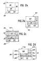
- FIG. 2a shows, by way of example, the decomposition of a block 22, in motion, into a plurality of sub-blocks 24-34.
- a movement analysis of each of the sub-blocks is carried out by the movement detection means 6.
- the movement detection means 6 For example, suppose that the sub-blocks 28 and 30 are in movement. These sub-blocks are represented in FIG. 2b by a hatched area.
- an identification code of the sub-block noting the size of the sub-block and its position in the block or in the image is transmitted on the transmission line, with a code for not refreshing said sub-block.
- each sub-block is compensated for by searching for a sub-block of the same size in the previous image and by transmission of the displacement vector between said sub-block and the identical sub-block. from the previous image. If the compensation is not perfect, the difference between the sub-block and the estimate of said sub-block deduced from the previous image is coded by transformation and quantification.
- each sub-block is treated separately. It may be advantageous in certain cases to group the moving sub-blocks, or at least some of them, so as to reduce the number of moving sub-blocks to be transmitted.
- FIG. 2c it is possible to define a new sub-block 36 including the moving sub-blocks 28, 30.
- This sub-block 36 also contains part of the fixed sub-block 24. It it is also possible to group the remaining fixed sub-blocks. In FIG. 2c, these sub-blocks have been grouped into two sub-blocks 38, 40.
- the moving sub-blocks 28, 30, shown in FIG. 2b can, when they are coded by motion compensation and the compensation is not perfect, be decomposed them - even in several parts called elementary blocks.
- the sub-block 28 has been broken down into three elementary blocks 28a, 28b, 28c, the latter two being in motion.
- the sub-block 30 has been broken down into 5 elementary blocks 30a-30e, of which the elementary blocks 30c and 30e are in motion.
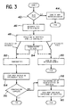
- the first step of the method is a test 42 for detecting movement in the block.
- This classic step is carried out, in the circuit of FIG. 1, by the subtractor 2 which receives on one input the block and on another input the corresponding block of the previous image, and the motion detector 6 which analyzes the difference of the blocks delivered by the subtractor 2.
- the block of the current image is fixed and on the transmission line, by an operation 44, a code of non-refreshment of the block and an identification code of this block in the image are transmitted. .
- the block is in motion, in accordance with the invention, there is an operation 46 for breaking down the block into a plurality of sub-blocks.
- any decomposition is possible.
- the sub-blocks are not necessarily identical.
- the operation 46 for breaking down into sub-blocks performed by the detection means 6 is followed by an operation 48 for detecting movement in the sub-blocks. This is done in the same way as motion detection in the block.
- the sub-blocks are then divided into two sets, a set of moving sub-blocks and a set of fixed sub-blocks.
- the procedure is the same as for a fixed block, that is to say that a non-refreshing code of said sub-block and an identification code of said sub-block are emitted in the image. (operation 50).
- the processing continues with a compensation operation 52. This is carried out by the compensation means 12 of the circuit of FIG. 1.
- FIGS. 4 to 8 show the different possible cases of moving sub-blocks in a moving block, in which the block is broken down into four identical sub-blocks.
- FIGS. 4a to 4d illustrate the 4 possibilities corresponding to a single moving sub-block.
- FIGS. 5a to 5d illustrate the four possibilities of having two contiguous sub-blocks in motion
- FIGS. 6a to 6b the two possibilities of having two sub-blocks in motion ment arranged on the same diagonal.
- Figures 7a to 7d show the four possibilities of having three moving sub-blocks and Figure 8 shows the case where the four sub-blocks are moving.
- each moving sub-block can be compensated separately. It is also possible, as shown in FIG. 2c, to group several moving sub-blocks to define a new moving sub-block. This optional operation 54 is carried out after operation 48 and before operations 50 and 52.
- the two moving sub-blocks can be grouped together in a single moving sub-block in FIGS. 5a to 5d and, in the same way, the two fixed sub-blocks can be grouped together in a single fixed sub-block. in these figures.
- the new moving sub-block is then equal to the complete block as shown in FIG. 8.
- the moving blocks can be classified into three categories A, B, C corresponding respectively to blocks in which the new moving sub-block has a size of a single sub-block, of two sub-blocks and of four sub-blocks. These categories are noted above the blocks in Figures 4 to 8.
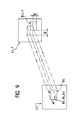
- the compensation operation 52 is known. It consists in measuring the displacement of the sub-block between the previous image and the current image.
- FIG. 9 shows a sub-block B of size N'xM ', where N' is equal to N or N / 2 and M 'is equal to M or M / 2, of the current image I.
- this block denoted B 1-1 , occupies a different position.
- the compensation consists in evaluating the coordinates p and q of the displacement vector of said sub-block between the two images.
- Compensation consists in finding the values p and q of the coordinates p, q of the displacement vector so as to minimize:
- a block of category C can become a perfectly compensated block, a block of category A, of category B or it can remain a block of category C.
- a block of category B can be perfectly compensated, or give a block of category A or remain a block of category B.
- a block of category A can be perfectly compensated or remain a block of category A.
- an operation 54 is carried out on the transmission line of a code representative of the value of the displacement vector and of an identification code of the sub-block.
- the transformation is carried out by the transformation means 8 of the circuit of FIG. 1.
- the most used transforms are the discrete cosine transform, the discrete highly correlated transform, the HADA-MARD transform or the HAAR transform.
- Another method of calculating the transform of the moving sub-blocks in the blocks of FIGS. 4 and 5 consists in symmetrizing these blocks by replacing the fixed sub-blocks by the moving sub-block (s).
- the reduced sub-blocks of the incompletely compensated sub-blocks are transmitted in coded form after having been transformed and quantified.
- This processing can be replaced by another processing in which each uncompensated sub-block is itself decomposed into several elementary blocks, each elementary block then being treated as are the sub-blocks.
- FIG. 10 shows a flowchart illustrating this variant of the method of the invention.
- the processing successively comprises an operation 62 for decomposing an uncompensated sub-block into elementary blocks, an operation 64 for analyzing the movement in the elementary blocks, an operation 66 for transmitting a non-refresh code for the fixed elementary blocks, and an operation 68 of compensation on the elementary blocks in motion.
- the operation 64 for detecting movement in the elementary blocks can be followed by an operation 70 for rearranging the elementary blocks, similar to the operation 54 in the flow diagram of FIG. 3.
- a code representative of the displacement vector of said elementary block and an identification code of this elementary block are transmitted.
- a test 72 is carried out to determine whether the compensation is perfect. If this is not the case, the reduced elementary block equal to the difference between the elementary block and its estimate, that is to say the elementary block of the previous image shifted by the value of the displacement vector, is transformed and then quantified during an operation 76. Finally, a code representative of said quantized elementary block is emitted (operation 78).
- Steps 72, 74, 76 and 78 applied to the elementary blocks are respectively analogous to steps 54, 56, 58 and 60 applied to the sub-blocks.
- step 64 or step 70 is followed only by steps 76 and 78.
Landscapes
- Engineering & Computer Science (AREA)
- Multimedia (AREA)
- Signal Processing (AREA)
- Compression Or Coding Systems Of Tv Signals (AREA)
Claims (8)
- . 1. Verfahren zur Transformationscodierung für die Übertragung eines Bildsignals über eine Übertragungsleitung, das aus einer Folge von Halbbildern besteht, die jeweils ein Bild enthalten, wobei das Verfahren eine Zerlegungsstufe des Bildes in Blöcke umfaßt, wobei ein Block eine Gruppe von digitalen Daten enthält, die in Matrixform angeordnet sind und einen Teil des Bildes repräsentiert, wobei das Verfahren für jeden Block die folgenden Stufen aufweist:die Ermittlung der Bewegung des Blocks durch Vergleich des Blocks des laufenden Bilds mit dem entsprechenden Block des vorhergehenden Bilds,wenn keine Bewegung in dem Block ermittelt wird, die Aussendung eines Nicht-Auffrischungscodes des Blocks und eines Identifikationscodes des Blocks im Bild auf die Übertragungsleitung, und gekennzeichnet durch den folgenden Schritt:wenn eine Bewegung in dem Block ermittelt wird: die Zerlegung des Blocks in mehrere Unterblöcke, die Bewegungsermittlung in jedem Unterblock des Blocks durch Vergleich mit dem entsprechenden Unterblock des entsprechenden Blocks des vorhergehenden Bilds und die Aussendung eines Funktionscodes der Bewegung des Unterblocks auf die Übertragungsleitung.
- 2. Verfahren nach Anspruch 1, dadurch gekennzeichnet, daß man jeden Unterblock in Bewegung in eine Gruppe von Elementärblöcken verlegt und daß man für jeden der genannten Elementarblöcke die Bewegung analysiert und man den genannten Elementarblock in Abhängigkeit vom Resultat der Bewegungsermittlung codiert.
- 3. Verfahren nach einem der Ansprüche 1 und 2, dadurch gekennzeichnet, daß für jeden Unterblock, wenn keine Bewegung in dem Unterblock ermittelt wird, man einen Nicht-Auffrichschungscode des Unterblocks und einen Identifikationscode des Unterblocks im Bild aussendet, und wenn eine Bewegung in dem Unterblock ermittelt wird, man den Verschiebungsvektor des genannten Unterblocks zwischen dem vorhergehenden Bild und dem laufenden Bild ermittelt, man die Bewegung des genannten Unterblocks in Abhängigkeit von dem Verschiebungsvektor kompensiert und man auf die Übertragungsleitung einen Funktionscode der Kompensation aussendet.
- 4. Verfahren nach Anspruch 3, dadurch gekennzeichnet, daß für jeden kompensierten Unterblock, dessen Kompensation vollständig ist, man auf die Übertragungsleitung einen Code aussendet, der für den Verschiebungsvektor repräsentativ ist, sowie einen Identifikationscode des Unterblocks im Bild.
- 5. Verfahren nach Anspruch 3, dadurch gekennzeichnet, daß für jeden kompensierten Unterblock, dessen Kompensation nicht vollständig ist, man einen Unterblock berechnet, der um die Differenz zwischen dem Unterbloc und seiner Abschätzung reduziert ist, man den genannten reduzierten Unterblock durch einen räumlich-zeitlichen Transformationsoperator codiert und man auf die Übertragungsleitung einen Code aussendet, der für die Daten repräsentativ ist, die in dem reduzierten, transformierten, quantisierten Unterblock enthalten sind, sowie einen Identifikationscode des genannten Unterblocks im Bild.
- 6. Verfahren nach Anspruch 3, dadurch gekennzeichnet, daß für jeden kompensierten Unterblock, dessen Kompensation nicht vollständig ist, man den genannten Unterblock im Elementarblöcke zerlegt, man die Bewegung jedes Elementarblocks ermittelt und man für jeden Elementarblock auf die Übertragungsleitung einen Funktionscode der Bewegung des genannten Elementarblocks aussendet.
- 7. Verfahren nach einem der Ansprüche 1 und 2, dadurch gekennzeichnet, daß für jeden Unterblock, wenn keine Bewegung in dem Unterblock ermittelt wird, man auf die Übertragungsleitung einen Nicht-Auffrischungscode des genannten Unterblocks und einen Identifikationscode des genannten Unterblocks im Bild aussendet und, wenn eine Bewegung in dem genannten Unterblock ermittelt wird, man einen Unterblock berechnet, der um die Differenz zwischen dem genannten Unterblock und dem entsprechenden Unterblock des vorhergehenden Bildes reduziert ist, und man auf die Übertragungsleitung einen Funktionscode des genannten reduzierten Unterblocks aussendet.
- 8. Verfahren nach Anspruch 7, dadurch gekennzeichnet, daß der genannte Funktionscode des genannten reduzierten Unterblocks ein Code ist, der für den reduzierten, um einen räumlich-zeitlichen und quantisierten Transformationsoperator transformierten Unterblock repräsentativ ist.
Applications Claiming Priority (2)
| Application Number | Priority Date | Filing Date | Title |
|---|---|---|---|
| FR8607713A FR2599577B1 (fr) | 1986-05-29 | 1986-05-29 | Procede de codage par transformation pour la transmission de signaux d'image. |
| FR8607713 | 1986-05-29 |
Publications (2)
| Publication Number | Publication Date |
|---|---|
| EP0248711A1 EP0248711A1 (de) | 1987-12-09 |
| EP0248711B1 true EP0248711B1 (de) | 1991-02-06 |
Family
ID=9335777
Family Applications (1)
| Application Number | Title | Priority Date | Filing Date |
|---|---|---|---|
| EP87401183A Expired - Lifetime EP0248711B1 (de) | 1986-05-29 | 1987-05-26 | Verfahren zur Transformationskodierung für die Übertragung von Bildsignalen |
Country Status (7)
| Country | Link |
|---|---|
| US (1) | US4796087A (de) |
| EP (1) | EP0248711B1 (de) |
| JP (1) | JPS62291280A (de) |
| DE (1) | DE3767919D1 (de) |
| FI (1) | FI86241C (de) |
| FR (1) | FR2599577B1 (de) |
| NO (1) | NO872245L (de) |
Families Citing this family (81)
| Publication number | Priority date | Publication date | Assignee | Title |
|---|---|---|---|---|
| EP0290085B1 (de) * | 1987-05-06 | 1996-03-20 | Philips Patentverwaltung GmbH | System zur Übertragung von Videobildern |
| DE3853554T2 (de) * | 1987-06-09 | 1995-08-24 | Sony Corp | Bewegungsvektorabschätzung in Fernsehbildern. |
| US5079630A (en) * | 1987-10-05 | 1992-01-07 | Intel Corporation | Adaptive video compression system |
| US5040060A (en) * | 1987-12-01 | 1991-08-13 | Canon Kabushiki Kaisha | Image information transmission system with compression based on still-image redundancy |
| DE68909271T2 (de) * | 1988-02-23 | 1994-03-24 | Philips Nv | Verfahren und Anordnung zum Abschätzen des Bewegungsausmasses bei einem Bildelement eines Fernsehbildes. |
| FR2628276B1 (fr) * | 1988-03-02 | 1991-06-28 | France Etat | Procede de reduction de debit d'une sequence de donnees d'assistance a la reconstitution d'une image electronique a partir d'un signal sous-echantillonne |
| FR2633468B1 (fr) * | 1988-06-24 | 1990-11-09 | France Etat | Procede de codage de donnees d'assistance a la reconstruction d'images electroniques animees sous-echantillonnees |
| JPH082107B2 (ja) * | 1990-03-02 | 1996-01-10 | 国際電信電話株式会社 | 動画像のハイブリッド符号化方法及びその装置 |
| US5253275A (en) * | 1991-01-07 | 1993-10-12 | H. Lee Browne | Audio and video transmission and receiving system |
| SE469866B (sv) * | 1991-04-12 | 1993-09-27 | Dv Sweden Ab | Metod för estimering av rörelseinnehåll i videosignaler |
| EP0533195A2 (de) * | 1991-09-20 | 1993-03-24 | Sony Corporation | Vorrichtung zum Kodieren und/oder Dekodieren von Bildsignalen |
| JP3263960B2 (ja) * | 1991-10-22 | 2002-03-11 | ソニー株式会社 | 動きベクトル符号器および復号器 |
| US5471248A (en) * | 1992-11-13 | 1995-11-28 | National Semiconductor Corporation | System for tile coding of moving images |
| KR950006776B1 (ko) * | 1993-01-14 | 1995-06-22 | 삼성전자주식회사 | 디지탈 영상 데이타의 보간방법 및 회로 |
| AU6099594A (en) * | 1993-02-03 | 1994-08-29 | Qualcomm Incorporated | Interframe video encoding and decoding system |
| FI94306C (fi) * | 1993-07-15 | 1995-08-10 | Nokia Technology Gmbh | Menetelmä televisiokuvan pienten kuvasegmenttien liikevektoreiden määrittämiseksi |
| DE69423166T2 (de) * | 1993-09-08 | 2000-07-06 | Thomson Consumer Electronics | Verfahren und Vorrichtung zur Bewegungsauswertung mit Blockübereinstimmung |
| GB2283876B (en) * | 1993-11-09 | 1998-06-24 | Matsushita Electric Industrial Co Ltd | Encoding and decoding code sequences and frames |
| JPH07200833A (ja) * | 1993-12-08 | 1995-08-04 | Nec Corp | 画像化システムにおいて移動物体の数を決定し画像の点と移動物体とを関連させる方法 |
| US5812198A (en) * | 1994-05-30 | 1998-09-22 | Ntt Mobile Communications Network, Inc. | Video coding decoding apparatus |
| US5594504A (en) * | 1994-07-06 | 1997-01-14 | Lucent Technologies Inc. | Predictive video coding using a motion vector updating routine |
| DE69524235T2 (de) * | 1994-09-02 | 2002-07-18 | Sarnoff Corp., Princeton | Verfahren und vorrichtung zur global-zu-lokal-block-bewegungsschätzung |
| DE69518128T2 (de) * | 1994-09-21 | 2001-03-29 | Kabushiki Kaisha Toshiba, Kawasaki | Bilddatenverarbeitungsvorrichtung mit Bilddatenteilungsfunktion und Verfahren zur Verarbeitung von Bilddaten |
| EP1098527A1 (de) * | 1994-11-04 | 2001-05-09 | Matsushita Electric Industrial Co., Ltd. | Bildkodierungs- und -dekodierungsvorrichtung |
| US5802211A (en) * | 1994-12-30 | 1998-09-01 | Harris Corporation | Method and apparatus for transmitting and utilizing analog encoded information |
| US6002802A (en) * | 1995-10-27 | 1999-12-14 | Kabushiki Kaisha Toshiba | Video encoding and decoding apparatus |
| DE19603808C1 (de) * | 1996-02-02 | 1997-04-17 | Siemens Ag | Anordnung und Verfahren zur Codierung und Decodierung von mit einem blockbasierten Codierungsverfahren codierten Bildern |
| US5745700A (en) * | 1996-05-13 | 1998-04-28 | International Business Machines Corporation | Multi media video matrix address decoder |
| KR100235064B1 (ko) * | 1996-05-23 | 1999-12-15 | 전주범 | 재배열된 블록 기반 부호화 기법을 이용하여 비디오 신호의 물체영역을 부호화하기 위한 장치 |
| US6205253B1 (en) | 1996-08-19 | 2001-03-20 | Harris Corporation | Method and apparatus for transmitting and utilizing analog encoded information |
| US6786420B1 (en) | 1997-07-15 | 2004-09-07 | Silverbrook Research Pty. Ltd. | Data distribution mechanism in the form of ink dots on cards |
| EP0891100A1 (de) * | 1997-07-08 | 1999-01-13 | Canon Kabushiki Kaisha | Verfahren und Vorrichtung zur Kodierung von Daten, insbesondere digitalen Bildern und Bildsequenzen |
| FR2766033A1 (fr) * | 1997-07-08 | 1999-01-15 | Canon Kk | Procede et dispositif de codage et decodage de donnees, notamment de sequences d'images numeriques |
| US6618117B2 (en) | 1997-07-12 | 2003-09-09 | Silverbrook Research Pty Ltd | Image sensing apparatus including a microcontroller |
| US7551201B2 (en) * | 1997-07-15 | 2009-06-23 | Silverbrook Research Pty Ltd | Image capture and processing device for a print on demand digital camera system |
| US7110024B1 (en) | 1997-07-15 | 2006-09-19 | Silverbrook Research Pty Ltd | Digital camera system having motion deblurring means |
| US6690419B1 (en) * | 1997-07-15 | 2004-02-10 | Silverbrook Research Pty Ltd | Utilising eye detection methods for image processing in a digital image camera |
| US6879341B1 (en) | 1997-07-15 | 2005-04-12 | Silverbrook Research Pty Ltd | Digital camera system containing a VLIW vector processor |
| US6624848B1 (en) | 1997-07-15 | 2003-09-23 | Silverbrook Research Pty Ltd | Cascading image modification using multiple digital cameras incorporating image processing |
| EP0905982A3 (de) * | 1997-09-30 | 1999-07-07 | Canon Kabushiki Kaisha | Verfahren und Vorrichtung zur Kodierung und Dekodierung von Daten, insbesondere Digitalbildfolgen |
| EP1086592B1 (de) * | 1998-06-05 | 2003-05-07 | Innomedia Pte Ltd. | Verfahren und vorrichtung zur extraktion des hintergrunds zwecks verringerung der anzahl codierter blöcke bei der videokodierung |
| AUPP702098A0 (en) | 1998-11-09 | 1998-12-03 | Silverbrook Research Pty Ltd | Image creation method and apparatus (ART73) |
| US6563953B2 (en) * | 1998-11-30 | 2003-05-13 | Microsoft Corporation | Predictive image compression using a single variable length code for both the luminance and chrominance blocks for each macroblock |
| US6983018B1 (en) | 1998-11-30 | 2006-01-03 | Microsoft Corporation | Efficient motion vector coding for video compression |
| AUPQ056099A0 (en) * | 1999-05-25 | 1999-06-17 | Silverbrook Research Pty Ltd | A method and apparatus (pprint01) |
| AU2001227068A1 (en) * | 2000-01-20 | 2001-07-31 | Kyowa Hakko Kogyo Co. Ltd. | Method of detecting or quantifying environmental hormones |
| CN101448162B (zh) | 2001-12-17 | 2013-01-02 | 微软公司 | 处理视频图像的方法 |
| AU2002351389A1 (en) | 2001-12-17 | 2003-06-30 | Microsoft Corporation | Skip macroblock coding |
| US7003035B2 (en) | 2002-01-25 | 2006-02-21 | Microsoft Corporation | Video coding methods and apparatuses |
| US7892183B2 (en) * | 2002-04-19 | 2011-02-22 | Pelikan Technologies, Inc. | Method and apparatus for body fluid sampling and analyte sensing |
| US20040001546A1 (en) * | 2002-06-03 | 2004-01-01 | Alexandros Tourapis | Spatiotemporal prediction for bidirectionally predictive (B) pictures and motion vector prediction for multi-picture reference motion compensation |
| US7280700B2 (en) * | 2002-07-05 | 2007-10-09 | Microsoft Corporation | Optimization techniques for data compression |
| US7154952B2 (en) | 2002-07-19 | 2006-12-26 | Microsoft Corporation | Timestamp-independent motion vector prediction for predictive (P) and bidirectionally predictive (B) pictures |
| US7499495B2 (en) * | 2003-07-18 | 2009-03-03 | Microsoft Corporation | Extended range motion vectors |
| US10554985B2 (en) | 2003-07-18 | 2020-02-04 | Microsoft Technology Licensing, Llc | DC coefficient signaling at small quantization step sizes |
| US7830963B2 (en) * | 2003-07-18 | 2010-11-09 | Microsoft Corporation | Decoding jointly coded transform type and subblock pattern information |
| US7738554B2 (en) * | 2003-07-18 | 2010-06-15 | Microsoft Corporation | DC coefficient signaling at small quantization step sizes |
| US7426308B2 (en) * | 2003-07-18 | 2008-09-16 | Microsoft Corporation | Intraframe and interframe interlace coding and decoding |
| US20050013498A1 (en) * | 2003-07-18 | 2005-01-20 | Microsoft Corporation | Coding of motion vector information |
| US7609763B2 (en) * | 2003-07-18 | 2009-10-27 | Microsoft Corporation | Advanced bi-directional predictive coding of video frames |
| US7616692B2 (en) | 2003-09-07 | 2009-11-10 | Microsoft Corporation | Hybrid motion vector prediction for interlaced forward-predicted fields |
| US7620106B2 (en) | 2003-09-07 | 2009-11-17 | Microsoft Corporation | Joint coding and decoding of a reference field selection and differential motion vector information |
| US7724827B2 (en) * | 2003-09-07 | 2010-05-25 | Microsoft Corporation | Multi-layer run level encoding and decoding |
| US7577200B2 (en) | 2003-09-07 | 2009-08-18 | Microsoft Corporation | Extended range variable length coding/decoding of differential motion vector information |
| US7317839B2 (en) * | 2003-09-07 | 2008-01-08 | Microsoft Corporation | Chroma motion vector derivation for interlaced forward-predicted fields |
| US7606308B2 (en) * | 2003-09-07 | 2009-10-20 | Microsoft Corporation | Signaling macroblock mode information for macroblocks of interlaced forward-predicted fields |
| US7623574B2 (en) | 2003-09-07 | 2009-11-24 | Microsoft Corporation | Selecting between dominant and non-dominant motion vector predictor polarities |
| US7092576B2 (en) * | 2003-09-07 | 2006-08-15 | Microsoft Corporation | Bitplane coding for macroblock field/frame coding type information |
| US8064520B2 (en) * | 2003-09-07 | 2011-11-22 | Microsoft Corporation | Advanced bi-directional predictive coding of interlaced video |
| US7567617B2 (en) * | 2003-09-07 | 2009-07-28 | Microsoft Corporation | Predicting motion vectors for fields of forward-predicted interlaced video frames |
| US7599438B2 (en) * | 2003-09-07 | 2009-10-06 | Microsoft Corporation | Motion vector block pattern coding and decoding |
| US7720154B2 (en) * | 2004-11-12 | 2010-05-18 | Industrial Technology Research Institute | System and method for fast variable-size motion estimation |
| FI20050113A7 (fi) * | 2005-02-01 | 2006-08-02 | Head Inhimillinen Tekijae Oy | Menetelmä kuvainformaation käsittelemiseksi |
| US9077960B2 (en) * | 2005-08-12 | 2015-07-07 | Microsoft Corporation | Non-zero coefficient block pattern coding |
| CN101227601B (zh) * | 2007-01-15 | 2011-09-14 | 飞思卡尔半导体公司 | 在视频再现中进行几何变换的方法和设备 |
| US8254455B2 (en) * | 2007-06-30 | 2012-08-28 | Microsoft Corporation | Computing collocated macroblock information for direct mode macroblocks |
| US8189666B2 (en) * | 2009-02-02 | 2012-05-29 | Microsoft Corporation | Local picture identifier and computation of co-located information |
| DE102021131955A1 (de) | 2021-12-03 | 2023-06-07 | Ipp Gmbh | Ladungsträger |
| DE202021106621U1 (de) | 2021-12-03 | 2023-03-24 | Ipp Gmbh | Ladungsträger |
| DE102021131954A1 (de) | 2021-12-03 | 2023-06-07 | Ipp Gmbh | Ladungsträger |
| DE202021106622U1 (de) | 2021-12-03 | 2023-03-27 | Ipp Gmbh | Ladungsträger |
Family Cites Families (5)
| Publication number | Priority date | Publication date | Assignee | Title |
|---|---|---|---|---|
| US4245248A (en) * | 1979-04-04 | 1981-01-13 | Bell Telephone Laboratories, Incorporated | Motion estimation and encoding of video signals in the transform domain |
| JPS60158786A (ja) * | 1984-01-30 | 1985-08-20 | Kokusai Denshin Denwa Co Ltd <Kdd> | 画像動き量検出方式 |
| US4661849A (en) * | 1985-06-03 | 1987-04-28 | Pictel Corporation | Method and apparatus for providing motion estimation signals for communicating image sequences |
| EP0207774B1 (de) * | 1985-07-02 | 1992-03-04 | Matsushita Electric Industrial Co., Ltd. | Vorrichtung zur Blockkodierung |
| US4661853A (en) * | 1985-11-01 | 1987-04-28 | Rca Corporation | Interfield image motion detector for video signals |
-
1986
- 1986-05-29 FR FR8607713A patent/FR2599577B1/fr not_active Expired
-
1987
- 1987-05-26 DE DE8787401183T patent/DE3767919D1/de not_active Expired - Lifetime
- 1987-05-26 EP EP87401183A patent/EP0248711B1/de not_active Expired - Lifetime
- 1987-05-27 NO NO872245A patent/NO872245L/no unknown
- 1987-05-28 JP JP62133259A patent/JPS62291280A/ja active Pending
- 1987-05-28 FI FI872380A patent/FI86241C/fi not_active IP Right Cessation
- 1987-06-01 US US07/059,333 patent/US4796087A/en not_active Expired - Lifetime
Also Published As
| Publication number | Publication date |
|---|---|
| FI872380A0 (fi) | 1987-05-28 |
| NO872245D0 (no) | 1987-05-27 |
| US4796087A (en) | 1989-01-03 |
| FR2599577A1 (fr) | 1987-12-04 |
| FI872380A7 (fi) | 1987-11-30 |
| EP0248711A1 (de) | 1987-12-09 |
| FR2599577B1 (fr) | 1988-08-05 |
| FI86241B (fi) | 1992-04-15 |
| NO872245L (no) | 1987-11-30 |
| JPS62291280A (ja) | 1987-12-18 |
| DE3767919D1 (de) | 1991-03-14 |
| FI86241C (fi) | 1992-07-27 |
Similar Documents
| Publication | Publication Date | Title |
|---|---|---|
| EP0248711B1 (de) | Verfahren zur Transformationskodierung für die Übertragung von Bildsignalen | |
| EP0247075B1 (de) | Hybrid-kodierungssystem durch umwandlung zur bildübertragung | |
| US6208692B1 (en) | Apparatus and method for performing scalable hierarchical motion estimation | |
| Konstantinides et al. | Noise estimation and filtering using block-based singular value decomposition | |
| EP0294357B1 (de) | Kodierungsverfahren von Bildsignalen | |
| FR2724083A1 (fr) | Procede d'estimation du mouvement bidirectionnel et dispositif correspondant | |
| FR3023112A1 (fr) | Procede de codage d'une image numerique, procede de decodage, dispositifs et programmes d'ordinateurs associes | |
| Ponomarenko et al. | Lossy compression of noisy images based on visual quality: a comprehensive study | |
| US6393156B1 (en) | Enhanced transform compatibility for standardized data compression | |
| WO2005086489A1 (fr) | Procede de codage et de decodage d'une sequence d'images par analyse temporelle hierarchique | |
| US6408101B1 (en) | Apparatus and method for employing M-ary pyramids to enhance feature-based classification and motion estimation | |
| EP0332553B1 (de) | Verfahren zur Wiederzuordnung der Wahl eines Unterabtastungsverfahrens nach dem Kriterium einer Datenraten-Reduktion einer Folge von Hilfsdaten, die zur Rekonstruktion eines unterabgetasteten, elektronischen Bildes dienen | |
| EP0825556B1 (de) | Blocktransformationskodierer für willkürlich geformte Bildsegmente | |
| EP3139608A1 (de) | Kompressionsverfahren eines videodatenflusses | |
| WO2018002474A1 (fr) | Procédé de codage intra d'une image numérique et procédé de décodage correspondant | |
| EP0360670B1 (de) | Verfahren zur Quantisierung mit einer variablen Schwelle in einer Transformationskodierung für die Übertragung von Bildsignalen | |
| EP1223554A1 (de) | Verfahren zur Rauschverminderung | |
| WO2014048946A1 (fr) | Procede et dispositif de prediction inter-image et procede et appareil de codage correspondants | |
| Ho et al. | Content-based scalable H. 263 video coding for road traffic monitoring | |
| Yamada et al. | Reduced-reference based video quality-metrics using representative-luminance values | |
| Ponomarenko et al. | Lossy and visually lossless compression of single-look SAR images | |
| KR100203695B1 (ko) | 물체 기반 부호화에 있어서의 텍스쳐 분류를 위한 전처리 장치 | |
| EP0427653A1 (de) | System zur Komprimierung von zu einer Bildfolge gehörenden Digitalbildern mittels adaptiver Quantifikation mit einer psycho-visuellen Transformationskonstruktion | |
| Fernandes et al. | On the Impact of LiDAR Point Cloud Compression on Remote Semantic Segmentation | |
| FR2907989A1 (fr) | Procede et dispositif d'optimisation de la compression d'un flux video |
Legal Events
| Date | Code | Title | Description |
|---|---|---|---|
| PUAI | Public reference made under article 153(3) epc to a published international application that has entered the european phase |
Free format text: ORIGINAL CODE: 0009012 |
|
| AK | Designated contracting states |
Kind code of ref document: A1 Designated state(s): DE GB IT SE |
|
| 17P | Request for examination filed |
Effective date: 19880516 |
|
| 17Q | First examination report despatched |
Effective date: 19900507 |
|
| GRAA | (expected) grant |
Free format text: ORIGINAL CODE: 0009210 |
|
| AK | Designated contracting states |
Kind code of ref document: B1 Designated state(s): DE GB IT SE |
|
| REF | Corresponds to: |
Ref document number: 3767919 Country of ref document: DE Date of ref document: 19910314 |
|
| ITF | It: translation for a ep patent filed | ||
| GBT | Gb: translation of ep patent filed (gb section 77(6)(a)/1977) | ||
| PLBE | No opposition filed within time limit |
Free format text: ORIGINAL CODE: 0009261 |
|
| STAA | Information on the status of an ep patent application or granted ep patent |
Free format text: STATUS: NO OPPOSITION FILED WITHIN TIME LIMIT |
|
| 26N | No opposition filed | ||
| EAL | Se: european patent in force in sweden |
Ref document number: 87401183.6 |
|
| REG | Reference to a national code |
Ref country code: GB Ref legal event code: IF02 |
|
| REG | Reference to a national code |
Ref country code: GB Ref legal event code: 732E |
|
| PGFP | Annual fee paid to national office [announced via postgrant information from national office to epo] |
Ref country code: SE Payment date: 20060425 Year of fee payment: 20 Ref country code: GB Payment date: 20060425 Year of fee payment: 20 |
|
| PGFP | Annual fee paid to national office [announced via postgrant information from national office to epo] |
Ref country code: DE Payment date: 20060505 Year of fee payment: 20 |
|
| PGFP | Annual fee paid to national office [announced via postgrant information from national office to epo] |
Ref country code: IT Payment date: 20060531 Year of fee payment: 20 |
|
| REG | Reference to a national code |
Ref country code: GB Ref legal event code: PE20 |
|
| EUG | Se: european patent has lapsed | ||
| PG25 | Lapsed in a contracting state [announced via postgrant information from national office to epo] |
Ref country code: GB Free format text: LAPSE BECAUSE OF EXPIRATION OF PROTECTION Effective date: 20070525 |