EP0248549A2 - Mesure gravimétrique dans un puits - Google Patents
Mesure gravimétrique dans un puits Download PDFInfo
- Publication number
- EP0248549A2 EP0248549A2 EP87304190A EP87304190A EP0248549A2 EP 0248549 A2 EP0248549 A2 EP 0248549A2 EP 87304190 A EP87304190 A EP 87304190A EP 87304190 A EP87304190 A EP 87304190A EP 0248549 A2 EP0248549 A2 EP 0248549A2
- Authority
- EP
- European Patent Office
- Prior art keywords
- piezoelectric
- transducers
- logging tool
- affixed
- gravity
- Prior art date
- Legal status (The legal status is an assumption and is not a legal conclusion. Google has not performed a legal analysis and makes no representation as to the accuracy of the status listed.)
- Granted
Links
Images
Classifications
-
- G—PHYSICS
- G01—MEASURING; TESTING
- G01V—GEOPHYSICS; GRAVITATIONAL MEASUREMENTS; DETECTING MASSES OR OBJECTS; TAGS
- G01V7/00—Measuring gravitational fields or waves; Gravimetric prospecting or detecting
Definitions
- the present invention relates to a method and apparatus for the continuous logging of the gravity gradient along an earth formation.
- Such tool is not practical for making continuous measurements since there is no accurate means for eliminating the force on the test mass due to tool acceleration, and consequently, accurate gravity readings cannot be made with the tool in motion.
- This limitation requires that the gravity tool be stopped for a period of several minutes at each point or station along the formation at which a gravity difference measurement is desired.
- Another limitation is that the vertical resolution of the tool is only about ten feet.
- the logging tool includes a container for the fluid column which maintains a constant pressure along the length of the column. Temperature is maintained constant along the column by an external heat absorber or by a heat absorbing element located with the column itself. Baffles are located within the fluid column to prevent thermally driven convection. A sound absorber is also located within the fluid column to inhibit the transmission of acoustic waves. The fluid column is further shock-mounted to prevent acoustic waves from being excited within the column itself.
- a method for conducting a gravimetry survey of an earth formation comprising the steps of:
- the invention resides in apparatus for conducting a gravimetry survey of an earth formation, comprising:
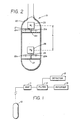
- FIG. 1 illustrates a gravity logging system with which the gravity gradient measurement method of the present invention may be utilized
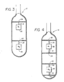
- FIGS. 2-4 illustrate alternate embodiments of the piezoelectric transducrs utilized in the gravity logging system of FIG. 1 for making the gravity gradient measurements.
- gravity gradient measurements are made by continuously moving a tool 10 along a borehole through a formation of interest.
- the gravimetric measurements are applied to an amplifier 11, a filter 12, difference detector 15, and a recorder 16 to produce a log of gravity gradient measurements as a function of tool location.
- the gravity measurements are coordinated with the depth of the tool in the borehole.
- the gravity gradient measurements of the logging tool 10 are accomplished by the measurement of changes in the force exerted on one or more piezoelectric transducers contained within the logging tool from acceleration due to gravity and tool motion as the tool traverses the formation of interest.
- the basic principle involved is that a piezoelectric crystal, when electrically excited, exhibits a characteristic natural frequency of vibration that changes according to the force (i.e., compression or tension) applied to the crystal.
- FIG. 2 illustrates one embodiment of a gravity logging tool for detecting such ⁇ T changes in the period of vibration of a piezoelectric crystal so that a gravity gradient ⁇ g can be determined.
- a first piezoelectric crystal (T1) 21 is vertically oriented with its lower end affixed to a horizontal support member 24 of the logging tool 10. Affixed to and supported by the upper end of the piezoelectric crystal 21 is a mass (M1) 23 utilized for loading the crystal 21. The crystal is excited into resonance at a characteristic frequency of vibration by the application of opposite polarity electrical pulses to its opposite surfaces 21a and 21b.
- a second piezoelectric crystal (T2) 25 is vertically oriented with its lower end affixed to a further horizontal support member 27 of the logging tool 10. Affixed to and supported by the upper end of the piezoelectric crystal 25 is a mass (M2) 26 for loading the crystal 25.
- the crystal is excited into resonance at a characteristic frequency of vibration by the application of opposite polarity electrical pulses to its opposite surfaces 25a and 25b.
- ⁇ F M1g1 - M2g2
- This gradient is determined by the difference detector 15 of FIG. 1 from the differences in the measured periods of vibrations T02 and T01 of the piezoelectric crystals 25 and 21, respectively.
- the piezoelectric crystals 21 and 25 may be vertically oriented with their upper ends affixed to horizontal support members 24 and 27, respectively, of logging tool 10.
- the masses (M1) 23 and (M2) 26 are then affixed to and suspended from the lower ends of piezoelectric crystals 21 and 25, respectively.
- the piezoelectrical crystal 21 has been replaced by a pair of crystals 30 and 31, while the piezoelectric crystal 25 has been replaced by a pair of crystals 40 and 41.
- Piezoelectric crystal 30 is affixed at its upper end to horizontal support member 33
- piezoelectric crystal 31 is affixed at its lower end to horizontal support 34.
- Mass (M1) 32 is affixed to and suspended from the lower end of crystal 30 and is also affixed to and supported by the upper end of crystal 31.
- the mass (M2) 42 is affixed between piezoelectric crystals 40 and 41 which are, in turn, affixed to horizontal support members 43 and 44, respectively.
- the crystals 30 and 40 will be in states of compression when crystals 31 and 41 are in states of tension.
- crystals 30 and 40 will be in states of tension when crystals 31 and 41 are in states of compression.
- Apparatus for carrying out the method of the present invention may employ piezoelectric transducers of the type shown in U.S. Patent Nos. 3,470,400 and 3,479,536. Techniques for electrically exciting and measuring the period of vibration of the crystals used in such transducers are fully disclosed in such patents.
- the piezoelectric transducers are preferably of the quartz crystal type used by ParaScientific Company for use in pressor sensors. These transducers may be coupled with a Hewlett-Packard HP-5370B time interval counter for providing a desired frequency resolution. Interval counter may be coupled to a Hewlett-Packard HP 85 or similar minicomputer for determining differences in the periods of vibration between the piezoelectric transducer locations. Preferably, the distance h between the piezoelectric transducer locations is about 1.5m (five feet).
- Temperature can be maintained reasonably constant by heating the column to a temperature greater than the expected maximum borehole temperature. Even better temperature control can be achieved by thermally insulating the column. This may be achieved by mounting it inside a vacuum flask. Still further, temperature control can be achieved by including a heat absorber within the housing. A very effective heat absorbing material is solid gallium which melts at about 31°C (87°F).
Landscapes
- Physics & Mathematics (AREA)
- Life Sciences & Earth Sciences (AREA)
- General Life Sciences & Earth Sciences (AREA)
- General Physics & Mathematics (AREA)
- Geophysics (AREA)
- Geophysics And Detection Of Objects (AREA)
- Measurement Of The Respiration, Hearing Ability, Form, And Blood Characteristics Of Living Organisms (AREA)
- Ultra Sonic Daignosis Equipment (AREA)
- Measurement And Recording Of Electrical Phenomena And Electrical Characteristics Of The Living Body (AREA)
- Magnetic Resonance Imaging Apparatus (AREA)
Applications Claiming Priority (2)
| Application Number | Priority Date | Filing Date | Title |
|---|---|---|---|
| US86885386A | 1986-05-30 | 1986-05-30 | |
| US868853 | 1986-05-30 |
Publications (3)
| Publication Number | Publication Date |
|---|---|
| EP0248549A2 true EP0248549A2 (fr) | 1987-12-09 |
| EP0248549A3 EP0248549A3 (en) | 1989-01-25 |
| EP0248549B1 EP0248549B1 (fr) | 1992-03-04 |
Family
ID=25352443
Family Applications (1)
| Application Number | Title | Priority Date | Filing Date |
|---|---|---|---|
| EP87304190A Expired - Lifetime EP0248549B1 (fr) | 1986-05-30 | 1987-05-12 | Mesure gravimétrique dans un puits |
Country Status (6)
| Country | Link |
|---|---|
| EP (1) | EP0248549B1 (fr) |
| BR (1) | BR8702545A (fr) |
| CA (1) | CA1293557C (fr) |
| DE (1) | DE3776970D1 (fr) |
| MX (1) | MX168445B (fr) |
| NO (1) | NO172207C (fr) |
Family Cites Families (3)
| Publication number | Priority date | Publication date | Assignee | Title |
|---|---|---|---|---|
| US3038338A (en) * | 1956-11-27 | 1962-06-12 | Boyd D Boitnott | Instrument for and method of airborne gravitational geophysical exploration |
| US4457077A (en) * | 1983-07-05 | 1984-07-03 | Standard Oil Company | Borehole gradiometer |
| US4602508A (en) * | 1984-10-04 | 1986-07-29 | Mobil Oil Corporation | Continuous gravity gradient logging |
-
1987
- 1987-05-01 CA CA000536160A patent/CA1293557C/fr not_active Expired - Lifetime
- 1987-05-12 EP EP87304190A patent/EP0248549B1/fr not_active Expired - Lifetime
- 1987-05-12 DE DE8787304190T patent/DE3776970D1/de not_active Expired - Lifetime
- 1987-05-19 NO NO872087A patent/NO172207C/no not_active IP Right Cessation
- 1987-05-19 BR BR8702545A patent/BR8702545A/pt not_active IP Right Cessation
- 1987-05-25 MX MX006622A patent/MX168445B/es unknown
Also Published As
| Publication number | Publication date |
|---|---|
| EP0248549A3 (en) | 1989-01-25 |
| BR8702545A (pt) | 1988-02-23 |
| NO872087D0 (no) | 1987-05-19 |
| CA1293557C (fr) | 1991-12-24 |
| NO872087L (no) | 1987-12-01 |
| EP0248549B1 (fr) | 1992-03-04 |
| NO172207B (no) | 1993-03-08 |
| MX168445B (es) | 1993-05-25 |
| NO172207C (no) | 1993-06-16 |
| DE3776970D1 (de) | 1992-04-09 |
Similar Documents
| Publication | Publication Date | Title |
|---|---|---|
| US4809545A (en) | Gravimetry logging | |
| US3625058A (en) | Apparatus for determining the filling level of a container | |
| RU2402793C2 (ru) | Улучшенная методика калибровки сейсмоприемника | |
| EP0355038B1 (fr) | Dispositif de mesure du niveau de l'interface entre un premier et un deuxième milieu dans un réservoir | |
| US8661894B2 (en) | Microgravimeter for geophysical prospecting | |
| AU2013394872B2 (en) | Method and device for the concurrent determination of fluid density and viscosity in-situ | |
| US20120072128A1 (en) | Determining Fluid Density | |
| NO335534B1 (no) | Enkelt rørborehulldensitometer | |
| EP1972965A2 (fr) | Procédé et appareil pour mesurer la gravité dans des trous de forage de faible diamètre | |
| US4602508A (en) | Continuous gravity gradient logging | |
| WO2009026004A1 (fr) | Procédé et appareil gravitationnels permettant de mesurer la profondeur verticale réelle dans un trou de sondage | |
| US3295360A (en) | Dynamic sensor | |
| US4596139A (en) | Depth referencing system for a borehole gravimetry system | |
| Howell et al. | The development and use of a high-precision downhole gravity meter | |
| EP0248549A2 (fr) | Mesure gravimétrique dans un puits | |
| US3999421A (en) | Powder bulk density instrument | |
| CA1115544A (fr) | Gradiometre a gravite avec laser a anneau | |
| US6307809B1 (en) | Geophone with optical fiber pressure sensor | |
| US4445371A (en) | Gravity meter and method | |
| US4412452A (en) | Harmonic oscillator for measuring dynamic elastic constants of rock materials | |
| SU682796A1 (ru) | Устройство дл измерени сдвиговой в зкости и упругости сред | |
| US4378698A (en) | Amplitude and phase detector in a harmonic oscillator system | |
| US4369506A (en) | Method and apparatus for shear wave logging | |
| US4409837A (en) | Method for measuring the resonance of rock material | |
| Feng | Optically powered electrical accelerometer and its field testing |
Legal Events
| Date | Code | Title | Description |
|---|---|---|---|
| PUAI | Public reference made under article 153(3) epc to a published international application that has entered the european phase |
Free format text: ORIGINAL CODE: 0009012 |
|
| AK | Designated contracting states |
Kind code of ref document: A2 Designated state(s): DE FR GB NL |
|
| PUAL | Search report despatched |
Free format text: ORIGINAL CODE: 0009013 |
|
| AK | Designated contracting states |
Kind code of ref document: A3 Designated state(s): DE FR GB NL |
|
| 17P | Request for examination filed |
Effective date: 19890608 |
|
| 17Q | First examination report despatched |
Effective date: 19900907 |
|
| GRAA | (expected) grant |
Free format text: ORIGINAL CODE: 0009210 |
|
| AK | Designated contracting states |
Kind code of ref document: B1 Designated state(s): DE FR GB NL |
|
| ET | Fr: translation filed | ||
| REF | Corresponds to: |
Ref document number: 3776970 Country of ref document: DE Date of ref document: 19920409 |
|
| PLBE | No opposition filed within time limit |
Free format text: ORIGINAL CODE: 0009261 |
|
| STAA | Information on the status of an ep patent application or granted ep patent |
Free format text: STATUS: NO OPPOSITION FILED WITHIN TIME LIMIT |
|
| 26N | No opposition filed | ||
| PGFP | Annual fee paid to national office [announced via postgrant information from national office to epo] |
Ref country code: FR Payment date: 20000419 Year of fee payment: 14 |
|
| PGFP | Annual fee paid to national office [announced via postgrant information from national office to epo] |
Ref country code: GB Payment date: 20000420 Year of fee payment: 14 Ref country code: DE Payment date: 20000420 Year of fee payment: 14 |
|
| PGFP | Annual fee paid to national office [announced via postgrant information from national office to epo] |
Ref country code: NL Payment date: 20000427 Year of fee payment: 14 |
|
| PG25 | Lapsed in a contracting state [announced via postgrant information from national office to epo] |
Ref country code: GB Free format text: LAPSE BECAUSE OF NON-PAYMENT OF DUE FEES Effective date: 20010512 |
|
| PG25 | Lapsed in a contracting state [announced via postgrant information from national office to epo] |
Ref country code: NL Free format text: LAPSE BECAUSE OF NON-PAYMENT OF DUE FEES Effective date: 20011201 |
|
| GBPC | Gb: european patent ceased through non-payment of renewal fee |
Effective date: 20010512 |
|
| PG25 | Lapsed in a contracting state [announced via postgrant information from national office to epo] |
Ref country code: FR Free format text: LAPSE BECAUSE OF NON-PAYMENT OF DUE FEES Effective date: 20020131 |
|
| NLV4 | Nl: lapsed or anulled due to non-payment of the annual fee |
Effective date: 20011201 |
|
| PG25 | Lapsed in a contracting state [announced via postgrant information from national office to epo] |
Ref country code: DE Free format text: LAPSE BECAUSE OF NON-PAYMENT OF DUE FEES Effective date: 20020301 |