EP0248094A2 - Appareil pour supporter un bâti en mouvement réciproque - Google Patents
Appareil pour supporter un bâti en mouvement réciproque Download PDFInfo
- Publication number
- EP0248094A2 EP0248094A2 EP86107296A EP86107296A EP0248094A2 EP 0248094 A2 EP0248094 A2 EP 0248094A2 EP 86107296 A EP86107296 A EP 86107296A EP 86107296 A EP86107296 A EP 86107296A EP 0248094 A2 EP0248094 A2 EP 0248094A2
- Authority
- EP
- European Patent Office
- Prior art keywords
- ram
- roller
- contact
- reciprocal movement
- planar
- Prior art date
- Legal status (The legal status is an assumption and is not a legal conclusion. Google has not performed a legal analysis and makes no representation as to the accuracy of the status listed.)
- Granted
Links
Images

Classifications
-
- B—PERFORMING OPERATIONS; TRANSPORTING
- B21—MECHANICAL METAL-WORKING WITHOUT ESSENTIALLY REMOVING MATERIAL; PUNCHING METAL
- B21D—WORKING OR PROCESSING OF SHEET METAL OR METAL TUBES, RODS OR PROFILES WITHOUT ESSENTIALLY REMOVING MATERIAL; PUNCHING METAL
- B21D22/00—Shaping without cutting, by stamping, spinning, or deep-drawing
- B21D22/20—Deep-drawing
-
- F—MECHANICAL ENGINEERING; LIGHTING; HEATING; WEAPONS; BLASTING
- F16—ENGINEERING ELEMENTS AND UNITS; GENERAL MEASURES FOR PRODUCING AND MAINTAINING EFFECTIVE FUNCTIONING OF MACHINES OR INSTALLATIONS; THERMAL INSULATION IN GENERAL
- F16F—SPRINGS; SHOCK-ABSORBERS; MEANS FOR DAMPING VIBRATION
- F16F7/00—Vibration-dampers; Shock-absorbers
Definitions
- This invention relates to providing a support for an elongated body so that the elongated body may be subjected to reciprocating movement and more particularly to a method for supporting a ram for reciprocating movement such as a ram used in machines for forming metal such as a can forming machine.
- a typical method manufacturing two piece cans consists of making a circular blank and then drawing the blank to form a shallow cup. The cup is fed in position ahead of a punch attached to the ram, and then is formed by the ram through a redraw die and a plurality of ironing dies located in a tool pack housing.
- Presses for directing the movement of the ram may be either mechanical or hydraulic.
- Exemplary of mechanical machines are U.S. Patent No. 3,702,559 to Hasselback et al. entitled “Can Bodymaking Machine” and 3,696,675 to Maytag entitled “Metal Working Crank and Slide Press Mechanism”.
- the ram in the Hasselback invention slides on guides with an attached cam follower cooperating with cam grooves on a barrel cam.
- the barrel cam is mounted on a shaft driven by an electric motor.
- the ram in the Maytag invention is mounted on a carriage with wheels which run on the top and bottom surfaces of hardened way strips. The wheels are adjusted with a predetermined amount of preload to avoid slack in the wheels.
- the carriage is driven by a crank and connecting rod attached to a parallel motion assembly.
- the foregoing objects are accomplished by this invention by providing closes means for supporting a body while permitting reciprocal movement of the body and is particularly directed to means for supporting a reciprocal ram used in apparatus for forming can bodies.
- the invention also provides means for dampening vibrations so as to limit damage to the apparatus normally resulting from such vibrations. Also, by minimizing vibrations, the can making efficiency is increased.
- a ram cradle assembly and a ram having an outer surface shaped to cooperate with angularly related surfaces on the ram cradle assembly are substituted for the carriage and hardened way strips of the apparatus disclosed in the Maytag patent.
- the ram cradle assembly comprises at least two spaced apart supports wherein each support comprises two angularly related rollers having generally cylindrical surfaces.
- a ram is provided with two angularly related planar surfaces extending in a direction generally parallel to the longitudinal axis of the ram.
- the angular relationship of the planar surfaces is the same as the angular relationship of the rollers so that the ram may be supported by the ram cradle assembly with the planar surfaces on the ram in contact with the cylindrical surfaces of the rollers.
- the weight of the ram is generally sufficient to insure that the ram remains in contact with the rollers.
- additional means are provided to apply a force urging the ram into firmer contact with the rollers.
- This force applying means comprises at least two spaced apart rollers, each of which has a generally cylindrical surface.
- the ram is provided with another planar surface extending in a direction generally parallel to the longitudinal axis of the ram and located so that it will be contacted by the force applying rollers. Any means, such as a spring, may be used to apply the force to the force applying rollers.
- the dampening means in the preferred embodiment of the invention, comprises a rope packing that is supported on the ram cradle assembly and is in circumferential contact with the adjacent portions of the outer surface of the ram.
- the preferred rope packing comprises Teflon coated cotton or fiberglass rope.
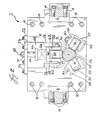
- a ram cradle assembly 2 which, in the preferred embodiment of the invention, is mounted on the frame 10 illustrated in Fig. 2 of the Maytag patent.
- the end portion (not shown) of the ram 4 extending from the right side of Fig. 1 is connected to the straight line motion assembly 20 of Fig. 2 of the Maytag patent.
- the end portion (not shown) of the ram 4 extending from the left side of Fig. 1 is connected to the redraw sleeve 40 of Fig. 2 of the Maytag patent.
- the ram cradle assembly 2 and the ram 4 of this invention have been substituted for the ram carriage 26 and the ram 27 of the Maytag patent, which patent is incorporated herein by reference.
- the ram cradle assembly 2 comprises a pair of rails 6 and 8 secured to the frame 2 in Fig. 6 of the Maytag patent.
- Support plates 10 and 12 extend between the rails 6 and 8 and are secured to each rail by suitable means such as the threaded bolts 14.
- a plurality of spacer blocks 16 extends between the support plates 10 and 12 and are secured in place by threaded bolts 18.
- a pair of freely rotatable support rollers 20 and 22 having angularly related generally cylindrical surfaces 24 and 26 are mounted in recesses in each of the plates 10 and 12 and secured thereto by suitable means such as bolts (not shown). As illustrated in Fig. 2, the rollers 20 and 22 are mounted between a pair of spaced apart lugs 28 and held in position by nuts 30.
- the ram 4 is provided with two angularly related planar surfaces 32 and 34, each of which extends in a direction generally parallel to the longitudinal axis of the ram 4.
- An opening 36 is provided in each of the plates 10 and 12 to provide for the passage of the ram 4 through the plates 10 and 12.
- the ram 4 is supported on the rollers 20 and 22 so that the planar surface 32 is in contact with and supported by generally cylindrical surface 24 and the planar surface 34 is in contact with an supported by generally cylindrical surface 26.
- the weight of the ram 4 cooperates with the angular relationship of the planar surfaces 32 and 34 and the angular relationship of the generally cylindrical surfaces 24 and 26 to retain the longitudinal axis of the ram 4 from movement in any direction perpendicular to the longitudinal axis during the reciprocal movement of the ram 4.
- Only two rollers and two planar surfaces are illustrated in Fig. 2, it is to be understood that more than two rollers and two planar surfaces may be used. In all instances, the angular relationship of the planar surfaces corresponds to the angular relationship of the generally cylindrical surfaces of the rollers.
- the weight of the ram is sufficient to hold it in position during the reciprocal movement.
- the preferred embodiment for accomplishing this rolling relationship is illustrated in Figs. 1 and 2 and comprises rollers 38 and 40 having generally cylindrical surfaces 42 and 44 and mounted on the plates 10 and 12.
- the mounting means comprises a dovetailed recess 46 in the plates 10 and 12 and a corresponding dovetailed projection 48 on a support member 50 which depends from a plate member 52 which is secured to each plate 10 and 12 by threaded bolts 54.
- the support member 50 has two spaced apart projecting portions 56 each of which is provided with a vertically extending recess 58.
- the rollers 38 and 40 are mounted in bearing blocks 60 which have projecting portions 62 mounted for sliding movement in the recesses 58.
- the relationship between the bearing blocks 60 and the recesses 58 is such so as to allow movement of the bearing block 60 in a vertical direction but to prevent relative movement in a horizontal direction.
- the upper portion of the bearing block 60 is attached to the lower portion of a spring 64.
- the upper portion of the spring 64 is attached to a plate 66 having a threaded member 68 projecting therefrom and extending through an opening in the plate member 52.
- a nut 70 is threaded on the member 68 so that the tension of the spring 64 may be adjusted.
- the ram 4 is provided with a planar surface 72 and, as illustrated in Fig. 2, is in contact with the generally cylindrical surface 42 of the roller 38.
- the springs 64 function to maintain the the rollers 38 and 40 in contact with the planar surface 72 and to apply an additional force on the ram 4 to ensure the desired rolling relationship between the planar surfaces and the generally cylindrical surfaces.
- the amount of force applied by rollers 38 and 40 is controlled by adjustment of the spring 64.
- the ram 4 is reciprocated at rates of hundreds of times per minute.
- dampening means are provided.
- the dampening means comprises a rope packing 74 in contact with the outer surface of the ram 4.
- the rope packing 74 is mounted in a holder 76 secured to a plate 78 mounted in spaced relationship to the plate 12 by spacing means 80.
- a packing push plate 82 is mounted on the holder 76 by threaded bolts 84.
- the rope packing 74 is a conventional half and half rope packing formed from Teflon coated cotton or fiberglass.
Landscapes
- Engineering & Computer Science (AREA)
- General Engineering & Computer Science (AREA)
- Mechanical Engineering (AREA)
- Presses And Accessory Devices Thereof (AREA)
- Transmission Devices (AREA)
- Advancing Webs (AREA)
Priority Applications (3)
| Application Number | Priority Date | Filing Date | Title |
|---|---|---|---|
| US06/818,406 US4614104A (en) | 1984-08-27 | 1986-01-13 | Apparatus for supporting a body for reciprocal movement |
| DE8686107296T DE3680913D1 (de) | 1986-05-28 | 1986-05-28 | Vorrichtung zum unterstuetzen eines koerpers zur hin- und herbewegung. |
| EP19860107296 EP0248094B1 (fr) | 1986-05-28 | 1986-05-28 | Appareil pour supporter un bâti en mouvement réciproque |
Applications Claiming Priority (1)
| Application Number | Priority Date | Filing Date | Title |
|---|---|---|---|
| EP19860107296 EP0248094B1 (fr) | 1986-05-28 | 1986-05-28 | Appareil pour supporter un bâti en mouvement réciproque |
Publications (3)
| Publication Number | Publication Date |
|---|---|
| EP0248094A2 true EP0248094A2 (fr) | 1987-12-09 |
| EP0248094A3 EP0248094A3 (en) | 1988-10-12 |
| EP0248094B1 EP0248094B1 (fr) | 1991-08-14 |
Family
ID=8195162
Family Applications (1)
| Application Number | Title | Priority Date | Filing Date |
|---|---|---|---|
| EP19860107296 Expired EP0248094B1 (fr) | 1984-08-27 | 1986-05-28 | Appareil pour supporter un bâti en mouvement réciproque |
Country Status (2)
| Country | Link |
|---|---|
| EP (1) | EP0248094B1 (fr) |
| DE (1) | DE3680913D1 (fr) |
Cited By (1)
| Publication number | Priority date | Publication date | Assignee | Title |
|---|---|---|---|---|
| EP3735329A4 (fr) * | 2018-01-03 | 2021-09-29 | Stolle Machinery Company, LLC | Ensemble d'amortissement pour vérin de machine de fabrication de corps de boîte |
Family Cites Families (6)
| Publication number | Priority date | Publication date | Assignee | Title |
|---|---|---|---|---|
| DE629531C (de) * | 1934-08-19 | 1936-11-16 | Wilhelm H Engelbertz | Vorrichtung zum Fuehren und Wechseln des Dornes in Rohrstossbaenken |
| US3314274A (en) * | 1964-01-23 | 1967-04-18 | Kaiser Aluminium Chem Corp | Apparatus for forming cup-shaped members |
| US3635069A (en) * | 1969-11-05 | 1972-01-18 | Dayton Reliable Tool & Mfg Co | Drive mechanism for multiple plungers |
| US3696657A (en) * | 1970-11-19 | 1972-10-10 | Coors Porcelain Co | Metal working crank and slide press mechanism |
| US3702559A (en) * | 1971-01-11 | 1972-11-14 | Stolle Corp | Can body making machine |
| JPS5741142A (en) * | 1980-08-27 | 1982-03-08 | Citizen Watch Co Ltd | Table device |
-
1986
- 1986-05-28 EP EP19860107296 patent/EP0248094B1/fr not_active Expired
- 1986-05-28 DE DE8686107296T patent/DE3680913D1/de not_active Expired - Fee Related
Cited By (2)
| Publication number | Priority date | Publication date | Assignee | Title |
|---|---|---|---|---|
| EP3735329A4 (fr) * | 2018-01-03 | 2021-09-29 | Stolle Machinery Company, LLC | Ensemble d'amortissement pour vérin de machine de fabrication de corps de boîte |
| CN115519044A (zh) * | 2018-01-03 | 2022-12-27 | 斯多里机械有限责任公司 | 用于制罐机冲锤的阻尼组件 |
Also Published As
| Publication number | Publication date |
|---|---|
| DE3680913D1 (de) | 1991-09-19 |
| EP0248094B1 (fr) | 1991-08-14 |
| EP0248094A3 (en) | 1988-10-12 |
Similar Documents
| Publication | Publication Date | Title |
|---|---|---|
| US4614104A (en) | Apparatus for supporting a body for reciprocal movement | |
| EP0116447B1 (fr) | Appareil pour travailler des bandes | |
| CA2720765C (fr) | Procede de production d'une piece de tole en forme de pot, a denture interieure et exterieure, et dispositif correspondant | |
| DE739254T1 (de) | Werkstück-verformendes werkzeug für eine stanzpresse | |
| US4934167A (en) | Can body making apparatus | |
| EP0860225B1 (fr) | Procédé et dispositif pour la fabrication d'une crémaillère | |
| US3620381A (en) | Horizontal high-speed transfer | |
| CN106475891B (zh) | 周向面加工单元、机床和操作方法 | |
| US5617755A (en) | Presses for drawing a hollow article | |
| US5138862A (en) | Ram guidance system | |
| EP0248094B1 (fr) | Appareil pour supporter un bâti en mouvement réciproque | |
| KR20170081905A (ko) | 복합프레스장치 | |
| US3871206A (en) | Continuous rotary press | |
| GB974990A (en) | Taper roll machine and method | |
| DE4035353A1 (de) | Nutenstanzanlage | |
| US3358591A (en) | Press | |
| CN209970544U (zh) | 齿轮轴固定夹具 | |
| US2808736A (en) | Counterbalancing means for punch press | |
| CA1288291C (fr) | Dispositif porteur d'un corps anime d'un mouvement alternatif | |
| JPS62286629A (ja) | 製缶機械 | |
| US3673849A (en) | Hydraulic press | |
| US3083635A (en) | Bolster assembly for presses | |
| US3670548A (en) | Apparatus for producing open-topped hollow articles | |
| CN209969194U (zh) | 一种伺服式水平两辊轧制装置 | |
| CN86104366A (zh) | 支承作往复运动的机体的装置 |
Legal Events
| Date | Code | Title | Description |
|---|---|---|---|
| PUAI | Public reference made under article 153(3) epc to a published international application that has entered the european phase |
Free format text: ORIGINAL CODE: 0009012 |
|
| AK | Designated contracting states |
Kind code of ref document: A2 Designated state(s): BE DE GB IT NL SE |
|
| PUAL | Search report despatched |
Free format text: ORIGINAL CODE: 0009013 |
|
| AK | Designated contracting states |
Kind code of ref document: A3 Designated state(s): BE DE GB IT NL SE |
|
| 17P | Request for examination filed |
Effective date: 19881110 |
|
| 17Q | First examination report despatched |
Effective date: 19900214 |
|
| GRAA | (expected) grant |
Free format text: ORIGINAL CODE: 0009210 |
|
| AK | Designated contracting states |
Kind code of ref document: B1 Designated state(s): BE DE GB IT NL SE |
|
| ITF | It: translation for a ep patent filed | ||
| REF | Corresponds to: |
Ref document number: 3680913 Country of ref document: DE Date of ref document: 19910919 |
|
| PLBE | No opposition filed within time limit |
Free format text: ORIGINAL CODE: 0009261 |
|
| STAA | Information on the status of an ep patent application or granted ep patent |
Free format text: STATUS: NO OPPOSITION FILED WITHIN TIME LIMIT |
|
| 26N | No opposition filed | ||
| PGFP | Annual fee paid to national office [announced via postgrant information from national office to epo] |
Ref country code: SE Payment date: 19940420 Year of fee payment: 9 Ref country code: DE Payment date: 19940420 Year of fee payment: 9 |
|
| PGFP | Annual fee paid to national office [announced via postgrant information from national office to epo] |
Ref country code: GB Payment date: 19940421 Year of fee payment: 9 |
|
| PGFP | Annual fee paid to national office [announced via postgrant information from national office to epo] |
Ref country code: BE Payment date: 19940527 Year of fee payment: 9 |
|
| PGFP | Annual fee paid to national office [announced via postgrant information from national office to epo] |
Ref country code: NL Payment date: 19940531 Year of fee payment: 9 |
|
| EAL | Se: european patent in force in sweden |
Ref document number: 86107296.5 |
|
| PG25 | Lapsed in a contracting state [announced via postgrant information from national office to epo] |
Ref country code: GB Effective date: 19950528 |
|
| PG25 | Lapsed in a contracting state [announced via postgrant information from national office to epo] |
Ref country code: SE Effective date: 19950529 |
|
| PG25 | Lapsed in a contracting state [announced via postgrant information from national office to epo] |
Ref country code: BE Effective date: 19950531 |
|
| BERE | Be: lapsed |
Owner name: BALL CORP. Effective date: 19950531 |
|
| PG25 | Lapsed in a contracting state [announced via postgrant information from national office to epo] |
Ref country code: NL Effective date: 19951201 |
|
| GBPC | Gb: european patent ceased through non-payment of renewal fee |
Effective date: 19950528 |
|
| NLV4 | Nl: lapsed or anulled due to non-payment of the annual fee |
Effective date: 19951201 |
|
| PG25 | Lapsed in a contracting state [announced via postgrant information from national office to epo] |
Ref country code: DE Effective date: 19960201 |
|
| EUG | Se: european patent has lapsed |
Ref document number: 86107296.5 |
|
| PG25 | Lapsed in a contracting state [announced via postgrant information from national office to epo] |
Ref country code: IT Free format text: LAPSE BECAUSE OF NON-PAYMENT OF DUE FEES;WARNING: LAPSES OF ITALIAN PATENTS WITH EFFECTIVE DATE BEFORE 2007 MAY HAVE OCCURRED AT ANY TIME BEFORE 2007. THE CORRECT EFFECTIVE DATE MAY BE DIFFERENT FROM THE ONE RECORDED. Effective date: 20050528 |