EP0247989B1 - Unabhängige, transportierbare Vorrichtung zum Heizen von physiologischen Flüssigkeiten - Google Patents
Unabhängige, transportierbare Vorrichtung zum Heizen von physiologischen Flüssigkeiten Download PDFInfo
- Publication number
- EP0247989B1 EP0247989B1 EP87850176A EP87850176A EP0247989B1 EP 0247989 B1 EP0247989 B1 EP 0247989B1 EP 87850176 A EP87850176 A EP 87850176A EP 87850176 A EP87850176 A EP 87850176A EP 0247989 B1 EP0247989 B1 EP 0247989B1
- Authority
- EP
- European Patent Office
- Prior art keywords
- fluid
- heat exchanger
- central tube
- warming
- connector means
- Prior art date
- Legal status (The legal status is an assumption and is not a legal conclusion. Google has not performed a legal analysis and makes no representation as to the accuracy of the status listed.)
- Expired - Lifetime
Links
- 239000012530 fluid Substances 0.000 title claims abstract description 95
- 238000010438 heat treatment Methods 0.000 title claims abstract description 27
- 238000010792 warming Methods 0.000 claims description 19
- 238000004891 communication Methods 0.000 claims description 4
- XAGFODPZIPBFFR-UHFFFAOYSA-N aluminium Chemical compound [Al] XAGFODPZIPBFFR-UHFFFAOYSA-N 0.000 claims description 2
- 229910052782 aluminium Inorganic materials 0.000 claims description 2
- 239000004411 aluminium Substances 0.000 claims 1
- 230000036512 infertility Effects 0.000 abstract description 4
- 238000005485 electric heating Methods 0.000 abstract description 2
- 210000004369 blood Anatomy 0.000 description 6
- 239000008280 blood Substances 0.000 description 6
- 210000004027 cell Anatomy 0.000 description 4
- 210000002445 nipple Anatomy 0.000 description 4
- 210000001124 body fluid Anatomy 0.000 description 3
- 239000010839 body fluid Substances 0.000 description 3
- 239000000523 sample Substances 0.000 description 3
- 230000001413 cellular effect Effects 0.000 description 2
- 238000007688 edging Methods 0.000 description 2
- 238000000034 method Methods 0.000 description 2
- 210000000601 blood cell Anatomy 0.000 description 1
- 230000017531 blood circulation Effects 0.000 description 1
- 239000004020 conductor Substances 0.000 description 1
- 238000010586 diagram Methods 0.000 description 1
- 210000005069 ears Anatomy 0.000 description 1
- 238000003780 insertion Methods 0.000 description 1
- 230000037431 insertion Effects 0.000 description 1
- 238000009434 installation Methods 0.000 description 1
- 238000002955 isolation Methods 0.000 description 1
- 239000000463 material Substances 0.000 description 1
- 238000012986 modification Methods 0.000 description 1
- 230000004048 modification Effects 0.000 description 1
- 238000013021 overheating Methods 0.000 description 1
Images

Classifications
-
- A—HUMAN NECESSITIES
- A61—MEDICAL OR VETERINARY SCIENCE; HYGIENE
- A61M—DEVICES FOR INTRODUCING MEDIA INTO, OR ONTO, THE BODY; DEVICES FOR TRANSDUCING BODY MEDIA OR FOR TAKING MEDIA FROM THE BODY; DEVICES FOR PRODUCING OR ENDING SLEEP OR STUPOR
- A61M5/00—Devices for bringing media into the body in a subcutaneous, intra-vascular or intramuscular way; Accessories therefor, e.g. filling or cleaning devices, arm-rests
- A61M5/44—Devices for bringing media into the body in a subcutaneous, intra-vascular or intramuscular way; Accessories therefor, e.g. filling or cleaning devices, arm-rests having means for cooling or heating the devices or media
-
- A—HUMAN NECESSITIES
- A61—MEDICAL OR VETERINARY SCIENCE; HYGIENE
- A61M—DEVICES FOR INTRODUCING MEDIA INTO, OR ONTO, THE BODY; DEVICES FOR TRANSDUCING BODY MEDIA OR FOR TAKING MEDIA FROM THE BODY; DEVICES FOR PRODUCING OR ENDING SLEEP OR STUPOR
- A61M2205/00—General characteristics of the apparatus
- A61M2205/36—General characteristics of the apparatus related to heating or cooling
- A61M2205/366—General characteristics of the apparatus related to heating or cooling by liquid heat exchangers
Definitions
- This invention relates to the art of devices used with physiological fluids.
- the invention is an apparatus for heating a physiological fluid before introduction into a patient, comprising in combination the means defined in the preamble to claim 1.
- fluids to be administered to a patient be heated.
- whole blood and packed cells are stored in refrigerators at a temperature of approximately 4°C.
- These fluids often are required to be administered to a patient within a short period of time, which necessitates warming them to a temperature approximately equal to that of the patient, i.e. 37°C.
- U.S.-A-3,614,385 Horstmann
- US-A-3,629,552 Edging
- US-A-4,476,867 Parks
- US-A-4,532,414 Shoah et al. teach systems for heating blood prior to being administered to a patient.
- the Horstmann, Edging, and Parks devices Use various heat exchangers whereby blood flows through a tube which communicates with a warming fluid in a heat exchanger. It is quite difficult to maintain sterility of the heating apparatus In these systems after the first use because of the complexity of the heat exchangers.
- the Shah et al. device is simply a heated plate having a groove therein for receiving a tube leading from the bag containing the fluid to be administered.
- U.S.-A-2,910,981 shows a device for conducting blood transfusions.
- a heat exchanger is in fluid communication with a heating element, and the blood to be administered passes through the heat exchanger before being administered to the patient.
- the heat exchanger comprises a central tube surrounded by an outer tube, and the heating fluid passes through the space between the inner and outer tubes.
- the heat exchanger is threadedly connected to valves at opposite ends. No structure is described for supporting the various elements described in the patent.
- EP-A-0 108 525 shows a heat exchanger with an inner, annular corrugated tube.
- the invention is a self-contained, free standing device which permits controlled, but rapid heating of cellular fluids as they are being administered to a patient.
- the heating of the cellular fluids is controlled to prevent damage to the fluids from various causes including overheating.
- the device comprises two major parts.
- a first part includes a heating element, a support pole, and a wheeled base.
- a second part comprises a heat exchanger and, optionally, a filter.
- the heat exchanger and filter are disposable and are removably attached to the support pole.
- the heat exchanger is disposable to facilitate each patient's use of a new, sterile heat exchanger.
- the heat exchanger is easily installed on the pole, which includes a fixed mounting block and a movable mounting block. Opposite ends of the heat exchanger comprise nipples which are received in O-ring containing recesses in the mounting blocks. Thus, installation and removal of the disposable heat exchanger are quite easy.
- the device may also include a filter which would be attached to an outlet of the heat exchanger. Sensors on the pole detect when the heat exchanger or the filter is in a correct place to control operation of the heating system.
- the heating device comprises a tank and a heating element in the outlet line of the tank.
- a pump circulates a heating fluid from the tank and heating element through the disposable heat exchanger.
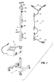
- Figure 1 is an exploded view of the apparatus in accordance with the invention.
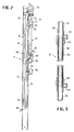
- Figure 2 is a longitudinal cross-section of the support pole.
- Figure 3 is a longitudinal cross-section of the heat exchanger.
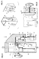
- Figure 4 is an enlarged cross-section of an upper end of the support pole.
- Figure 5 is an exploded perspective of a movable mounting block and the upper end of the support pole.
- Figure 6 is a side view of the upper end of the support pole shown in Figure 4.
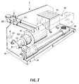
- Figure 7 is a perspective view of the heating element with the cover removed and the storage tank shown in phantom lines.
- Figure 8 is a schematic view showing the preferred fluid circuit.
- Figure 1 is an exploded view of a preferred embodiment of the invention.
- a base 2 which preferably has wheels for ease of mobility, supports a pole 4 and a heating unit 6.
- Pole 4 removably receives a disposable unit 8 which includes a heat exchanger 10 and a filter 12.
- Tube 14 is in fluid communication with one end of heat exchanger 10 and connects it to a pair of bags spikes 16.
- the bag spikes are known in the art and are used to puncture and allow the dispensing of a body fluid from a storage bag.
- Tube 18 connects a lower end of heat exchanger 10 to an upper end of filter 12 and tube 20 connects a lower end of filter 12 to cannula 22 to allow fluids to be introduced into a patient.
- the entire unit 8 is manufactured of an inexpensive material and is disposable to ensure sterility.
- Figure 2 is a longitudinal cross-section of pole 4 with heat exchanger 10 partially mounted thereon.
- Pole 4 includes a housing 24 which is attached to base 2 ( Figure 1) to extend substantially vertically.
- Housing 24 is preferably a hollow square tube, and hoses 26 and 28 extend along a hollow portion of housing 24.
- hoses 26 and 28 exit housing 24 via opening 30.
- electric conductor 32 extends along the hollow portion of housing 24 and exits by way of a second opening 34.
- Heat exchanger 10 is removably received by first detachable fluid connector 36 and second detachable fluid connector 38.
- the structure of fluid connectors 36 and 38 will be more fully described with respect to Figures 4 and 5.
- Detachable fluid connector 36 is mounted for vertical movement with respect to housing 24 to allow heat exchanger 10 to be easily attached to pole 4 and detached.
- Accordion element 40 is placed in hose 28 to permit fluid connector 36 to move vertically.
- Sensor 42 detects when fluid connector 36 is in its lowermost position (as shown in Figure 4), sensor 44 detects when heat exchanger 10 is in an operable position, and sensor 46 detects when filter 12 is in operable position.
- Filter 12 is supported on pole 4 by U-shaped bracket 48.
- the distance between the legs of the bracket is slightly less than the diameter of the filter so that it "snaps" into place.
- a U-shaped bracket 49 is located between connectors 36 and 38. Bracket 49 holds heat exchanger 10 aligned with connector 36 during insertion of the heat exchanger.
- Figure 3 is a longitudinal cross-section of heat exchanger 10.
- An inner tube 50 has ends 52 and 54 which are adapted to be received in respective fluid connectors 36 and 38.
- a central portion 56 of tube 50 is helically shaped to provide a helical groove on the exterior of tube 50.
- Tube 50 is preferably made of aluminum, and the helical surface is produced by twisting the tube.
- An outer tube 58 fits over the inner tube 50 in a central portion thereof.
- the space between the helical central portion 56 and the outer tube 58 forms a helical path extending between opposite ends of outer tube 58.
- An inlet connector 60 is secured to one end of outer tube 58 and includes connection 62 which receives tube 14 (see Figure 2). End 52 of inner tube 50 extends beyond the upper edge of inlet connector 60 to provide a nipple for engagement with fluid connectors 36 as will be more fully described with respect to Figure 4.
- Outlet connector 64 is secured to a second end of outer tube 58, provides connection 66 for attachment to tube 18, and allows end 54 to project to form a nipple for being received in fluid connector 38.
- Figure 4 is an enlarged cross section of an upper end of pole 4.
- Housing 24 has a slot 68 in one side thereof for receiving a projection 70 from fluid connector 36.
- Projection 70 has outwardly extending ears 72 (see Figure 5) to secure the fluid connector to the pole and yet to allow it to move in the direction indicated by the arrow in Figure 4.
- Elbow 74 is threadedly connected to projection 70 to connect hose 28 with inner passage 76.
- Recess 78 connects with passage 76 and receives nipple end 52 of heat exchanger 10.
- O-ring seal 80 is received in an enlarged portion of recess 78 to provide a fluid-tight seal. It will be appreciated that fluid passing through hose 28 is thus connected to inner tube 50 of heat exchanger 10.
- Figure 5 is an exploded view of the fluid connector 36 and the upper portion of housing 24.
- Fluid connector 38 is similar to fluid connector 36, except that connector 38 is secured to housing 24.
- heat exchanger 10 may be easily attached to pole 4 by inserting end 54 into fluid connector 38 and by lowering fluid connector 36 onto end 52. When this is accomplished, heat exchanger 10 will be supported mainly by fluid connectors 36 and 38.
- Figure 6 is a side view of the top portion of pole 4 with a bracket 82 shown in cross-section.
- Bracket 82 has a hole therethrough for supporting a rod 84 which in turn supports bags containing fluids to be administered to a patient.
- a threaded stem 86 engages rod 84 to allow rod 84 to be adjusted in height.
- Figure 7 is a perspective view of heating unit 6, with a cover removed.
- Figure 8 is a schematic flow diagram of the unit shown in Figure 7 and these two Figures will be discussed together.
- a base 88 supports electrical components 90, a pump motor 92, and a heater 94.
- a tank 96 sits on top of heater 94, and filter 98 is located between an outlet of the tank and an inlet of the heater.
- a fill port 100 is connected to the top of tank 96 to allow circulating fluid to be introduced into the system.
- Inlet 102 also connects to the top of tank 96 and receives circulating fluid from either hose 26 or 28, and outlet 104 supplies heated fluid to hose 28 or 26.
- the warming fluid is driven through the heat exchanger circuit by pump 106 which is connected to the pump motor by magnetic clutch 108.
- tank 96 includes an air vent and overflow tube 110, and a float switch 112.
- the float switch is in turn connected to a control circuit 114 to permit operation of the device only when sufficient fluid is present.
- Heater 94 comprises a tubular channel having an electric heating rod 116 therein, and the heating rod is connected to a temperature control circuit 118 which is in turn also connected to control circuit 114.
- Temperature control probe 120 is connected to temperature control circuit 118 to control energization of heating rod 116.
- a second temperature control probe 122 is also located in the outlet of heater 94 and is connected to control circuit 114 to ensure that the temperature does not exceed a predetermined level. If the temperature of the warming fluid is too high, the blood cells could be destroyed, and it is thus important either to automatically shut down the heating system or to activate an alarm such as that shown at 124.
- Power is provided through power cord 126, and the voltage is adjusted by an isolation transformer 128.
- a switch 130 activates the entire electrical system, and the operation of the system, including the fluid temperature is displayed on panel 132.
- the unit is rolled to a location adjacent to a patient, and a sterile unit 8 is installed between fluid connectors 36 and 38.
- Cannula 22 is attached to the patient, and bag spikes 16 are inserted into appropriate bags containing the desired fluid to be administered to the patient.
- Switch 130 is activated to begin the flow of heating fluid through the heat exchanger, and after the attendant has ascertained that a desired temperature has been reached in the heat exchanger, the fluid to be administered is allowed to pass into tube 14 to be warmed by the heat exchanger. If filter 12 has been placed in the circuit, the warmed body fluid then passes through the filter and into the patient. If filter 12 is not being used, tube 18 is connected directly to the cannula 22 for direct admission of the warm body fluid to the patient.
Landscapes
- Health & Medical Sciences (AREA)
- Animal Behavior & Ethology (AREA)
- Public Health (AREA)
- Anesthesiology (AREA)
- Biomedical Technology (AREA)
- Heart & Thoracic Surgery (AREA)
- Hematology (AREA)
- Engineering & Computer Science (AREA)
- Life Sciences & Earth Sciences (AREA)
- General Health & Medical Sciences (AREA)
- Vascular Medicine (AREA)
- Veterinary Medicine (AREA)
- Infusion, Injection, And Reservoir Apparatuses (AREA)
- External Artificial Organs (AREA)
- Medical Preparation Storing Or Oral Administration Devices (AREA)
- Thermotherapy And Cooling Therapy Devices (AREA)
- Cookers (AREA)
Claims (19)
- Eine Vorrichtung zum Erwärmen einer physiologischen Flüssigkeit vor einem Einbringen in einen Patienten, die in Kombination umfaßt
einen Wärmetauscher (10)
erste und zweite Flüssigkeitsverbindungseinrichtungen (36, 38) zum lösbaren Aufnehmen jeweiliger erster und zweiter Wärmeflüssigkeitsdurchgangsöffnungen (52, 54) des Wärmetauschers (10) und zum Erleichtern des Hindurchtretens einer Wärmeflüssigkeit und
eine Halteeinrichtung (4) zum Halten der ersten und zweiten Flüssigkeitsverbindungseinrichtungen,
wobei jede Flüssigkeitsverbindungseinrichtung (36, 38) einen Durchgang (76) zum Hindurchleiten der Wärmeflüssigkeit und Einrichtungen (78, 80) zum Eingreifen einer jeweiligen ersten oder zweiten Wärmeflüssigkeitsdurchgangsöffnung umfaßt, um der Wärmeflüssigkeit in dem Durchgang zu ermöglichen, mit der Durchgangsöffnung in Verbindung zu treten und physikalisch den Wärmetauscher in Zusammenarbeit mit der anderen der Flüssigkeitsverbindungseinrichtungen zu halten,
eine Flüssigkeitspumpe (92, 106, 108) zum Zirkulierenlassen der Wärmeflüssigkeit zu den ersten und zweiten Flüssigkeitsverbindungseinrichtungen, und
eine Temperatursteuereinrichtung (120) zum Steuern der Temperatur der Wärmeflüssigkeit,
dadurch gekennzeichnet, daß eine der ersten und zweiten Flüssigkeitsverbindungseinrichtungen (36, 38) beweglich an der Halteeinrichtung (4) für eine Bewegung in Bezug auf die Halteeinrichtung zwischen wenigstens ersten und zweiten Positionen befestigt ist, so daß die erste und zweite Flüssigkeitsverbindungseinrichtungen die Wärmeflüssigkeitsdurchgangsöffnungen (52, 54) eingreifen, wenn der eine der Flüssigkeitsverbinder in der ersten Position ist, und die Wärmeflüssigkeitsdurchgangsöffnungen freigeben, wenn die eine der Flüssigkeitsverbindungseinrichtungen in der zweiten Position ist. - Eine Vorrichtung gemäß Anspruch 1, dadurch gekennzeichnet, daß die Einrichtung zum Eingreifen eine Ausnehmung (78) zum Aufnehmen einer Flüssigkeitsdurchgangsöffnung umfaßt.
- Eine Vorrichtung gemäß Anspruch 2, dadurch gekennzeichnet, daß die Ausnehmung (78) eine Abdichteinrichtung (80) zum Verhindern von Lecken der Wärmeflüssigkeit einschließt.
- Eine Vorrichtung gemäß Anspruch 3, dadurch gekennzeichnet, daß die Abdichteinrichtung ein O-Ring (80) ist.
- Eine Vorrichtung gemäß Anspruch 1, dadurch gekennzeichnet, daß die Halteeinrichtung in einer ersten Richtung langgestreckt ist, wobei die eine der ersten und zweiten Verbindungseinrichtungen an der Halteeinrichtung für eine Linearbewegung in der Richtung auf die andere der ersten und zweiten Verbindungseinrichtung zu oder davon weg zwischen den ersten und zweiten Positionen befestigt ist, und die andere der ersten und zweiten Verbindungseinrichtungen in Bezug auf die Halteeinrichtung fest ist.
- Eine Vorrichtung gemäß Anspruch 5, dadurch gekennzeichnet, daß die Einrichtung zum Eingreifen eine zylindrische Ausnehmung (78) umfaßt und daß die zylindrische Ausnehmung der ersten Flüssigkeitsverbindungseinrichtung axial zu der zylindrischen Ausnehmung der zweiten Flüssigkeitsverbindungseinrichtung ausgerichtet ist.
- Eine Vorrichtung gemäß Anspruch 2, dadurch gekennzeichnet, daß eine Längsachse der Ausnehmung der ersten Flüssigkeitsverbindungseinrichtung parallel zu einer Längsachse der Ausnehmung der zweiten Flüssigkeitsverbindungseinrichtung ist, und daß die erste Flüssigkeitsverbindungseinrichtung für eine Linearbewegung in der Richtung der Längsachse befestigt ist.
- Eine Vorrichtung gemäß Anspruch 7, dadurch gekennzeichnet, daß der Wärmetauscher ein Zentralrohr (50) und ein äußeres Rohrs (58) aufweist, das eine Länge aufweist, die kürzer als diejenige des Zentralrohres ist, worin die ersten und zweiten Wärmeflüssigkeitsdurchgangsöffnungen (52, 54) Bereiche des Zentralrohres umfassen, die sich unterhalb der jeweiligen Enden des äußeren Rohres erstrecken, und die Zentralrohre und äußeren Rohre einen Durchgang für eine zu erwärmendene Flüssigkeit bilden.
- Eine Vorrichtung gemäß Anspruch 8, dadurch gekennzeichnet, daß der Wärmetauscher außerdem erste und zweite Endkappen (60, 64) aufweist, wobei jede der ersten und zweiten Endkappen einen ersten Teil, der abdichtend an einer äußeren Oberfläche eines jeweiligen Endes des äußeren Rohres gesichert ist, und einen zweiten Teil aufweist, der sich von dem ersten Teil weg erstreckt und zu einer Seite des Zentralrohres abdichtend eingegriffen wird.
- Eine Vorrichtung gemäß Anspruch 9, dadurch gekennzeichnet, daß der zweite Bereich der Kappeneinrichtungen einen mit der Seite des Zentralrohres in Kontakt stehenden offenen Zylinder umfaßt.
- Eine Vorrichtung gemäß Anspruch 1, worin der Wärmetauscher zum Steuern der Temperatur der physiologischen Flüssigkeit ein Zentralrohr (50) zum Führen einer temperaturüberwachten Flüssigkeit, ein äußeres Rohr (58), das kürzer als das Zentralrohr ist und einen Teil des Zentralrohres umgibt, um einen Durchgang für die physiologische Flüssigkeit zwischen dem Zentralrohr und äußeren Rohr zu bilden, und erste und zweite Endkappen (60, 64) umfaßt, dadurch gekennzeichnet, daß jede der Endkappen einen ersten Teil; der sich axial entlang der äußeren Oberfläche des äußeren Rohres erstreckt und an der äußeren Oberfläche abgedichtet und gesichert ist, und einen zweiten Teil aufweist, der das Zentralrohr abdichtend eingreift, wobei der zweite Teil eine längliche zylindrische Öffnung aufweist, die eine äußere Oberfläche des Zentralrohres eingreift und sich von dem ersten Teil weg erstreckt, und das Zentralrohr sich unterhalb jedes der zweiten Teile erstreckt und zwei längliche Verbindungen (52, 54) bildet, um gleitend in einer länglichen Ausnehmung aufgenommen zu werden.
- Ein Wärmetauscher gemäß Anspruch 11, dadurch gekennzeichnet, daß das Zentralrohr aus Aluminium ist.
- Ein Wärmetauscher gemäß Anspruch 11, dadurch gekennzeichnet, daß das Zentralrohr eine äußere Oberfläche (56) aufweist, die ein erhöhtes Oberflächengebiet liefert.
- Ein Wärmetauscher gemäß Anspruch 13, dadurch gekennzeichnet, daß die äußere Oberfläche spiralförmig ist und eine Längsachse des Zentralrohres geradlinig ist.
- Ein Wärmetauscher gemäß Anspruch 12, dadurch gekennzeichnet, daß jede der Endkappen eine Durchgangsöffnung (62, 66) einschließt, um eine zu erwärmende Flüssigkeit mit dem Durchgang in Verbindung zu bringen.
- Eine Vorrichtung gemäß Anspruch 8, dadurch gekennzeichnet, daß eine Heizeinrichtung (16) in Flüssigkeitsverbindung mit den Wärmeflüssigkeitsdurchgangsöffnungen ist.
- Eine Vorrichtung gemäß Anspruch 16, dadurch gekennzeichnet, daß die Heizeinrichtung ein elektrisches Flüssigkeitsheizelement (116), einen Vorratsbehälter (36), der die erste Wärmeflüssigkeit enthält, und eine Pumpeinrichtung (108) zum Zirkulierenlassen der ersten Wärmeflüssigkeit in einem Kreislauf, der das Heizelement, den Behälter, und das Zentralrohr des Wärmetauschers einschließt, umfaßt.
- Eine Vorrichtung gemäß Anspruch 16, dadurch gekennzeichnet, daß die Heizeinrichtung und die Halteeinrichtung an einer gemeinsamen, mit Rädern versehenen Basis (2) befestigt sind und daß die Vorrichtung außerdem Schaltereinrichtungen zum Detektieren, wenn der Wärmetauscher betriebsfähig an der Halteeinrichtung befestigt ist, umfaßt.
- Eine Vorrichtung gemäß Anspruch 9, dadurch gekennzeichnet, daß eine Filtereinrichtung (12) in Flüssigkeitsverbindung mit der zu erwärmenden Flüssigkeit ist.
Applications Claiming Priority (2)
| Application Number | Priority Date | Filing Date | Title |
|---|---|---|---|
| US06/866,910 US4759749A (en) | 1986-05-27 | 1986-05-27 | Heater for physiological fluids |
| US866910 | 1992-04-10 |
Publications (3)
| Publication Number | Publication Date |
|---|---|
| EP0247989A2 EP0247989A2 (de) | 1987-12-02 |
| EP0247989A3 EP0247989A3 (en) | 1990-11-22 |
| EP0247989B1 true EP0247989B1 (de) | 1995-09-06 |
Family
ID=25348705
Family Applications (1)
| Application Number | Title | Priority Date | Filing Date |
|---|---|---|---|
| EP87850176A Expired - Lifetime EP0247989B1 (de) | 1986-05-27 | 1987-05-26 | Unabhängige, transportierbare Vorrichtung zum Heizen von physiologischen Flüssigkeiten |
Country Status (8)
| Country | Link |
|---|---|
| US (2) | US4759749A (de) |
| EP (1) | EP0247989B1 (de) |
| JP (1) | JPH084626B2 (de) |
| AT (1) | ATE127350T1 (de) |
| CA (1) | CA1271796A (de) |
| DE (1) | DE3751504T2 (de) |
| ES (1) | ES2076932T3 (de) |
| GR (1) | GR3017835T3 (de) |
Cited By (1)
| Publication number | Priority date | Publication date | Assignee | Title |
|---|---|---|---|---|
| DE102017204776A1 (de) | 2016-03-23 | 2017-09-28 | WWT Technischer Gerätebau GmbH | Modularer Blutwärmer |
Families Citing this family (67)
| Publication number | Priority date | Publication date | Assignee | Title |
|---|---|---|---|---|
| US4874359A (en) * | 1987-12-14 | 1989-10-17 | White Frederick R | Power infuser |
| US5254094A (en) * | 1989-07-17 | 1993-10-19 | Starkey David L | Physiological fluid warmer |
| US5063994A (en) * | 1990-06-26 | 1991-11-12 | Level 1 Technologies, Inc. | Reflux fluid heated patient line |
| US5180896A (en) * | 1990-10-11 | 1993-01-19 | University Of Florida | System and method for in-line heating of medical fluid |
| DE4105781C1 (de) * | 1991-02-23 | 1992-01-02 | Fresenius Ag, 6380 Bad Homburg, De | |
| US5245693A (en) * | 1991-03-15 | 1993-09-14 | In-Touch Products Co. | Parenteral fluid warmer apparatus and disposable cassette utilizing thin, flexible heat-exchange membrane |
| US5381510A (en) * | 1991-03-15 | 1995-01-10 | In-Touch Products Co. | In-line fluid heating apparatus with gradation of heat energy from inlet to outlet |
| US5403281A (en) * | 1992-09-25 | 1995-04-04 | Minnesota Mining And Manufacturing Company | Inline heat exchanger and cardioplegia system |
| US5417274A (en) * | 1993-03-12 | 1995-05-23 | Verkaart; Wesley H. | Heater for physiological solutions effective at both low and high flow rates |
| US5514335A (en) * | 1993-10-25 | 1996-05-07 | Minnesota Mining And Manufacturing Company | Blood oxygenation system and reservoir and method of manufacture |
| US5807332A (en) * | 1994-03-22 | 1998-09-15 | Augustine Medical, Inc. | Tube apparatus for warming intravenous fluids within an air hose |
| US5514095A (en) * | 1994-04-04 | 1996-05-07 | Haemonetics Corporation | Apparatus for heating, filtering and eliminating gas from biological fluids |
| SI0723436T1 (en) * | 1994-07-08 | 2002-02-28 | Astrazeneca Ab | Multiple unit tableted dosage form i |
| US5817146A (en) * | 1995-11-09 | 1998-10-06 | Augustine Medical, Inc. | Patient warming system with IV fluid warmer |
| US5846224A (en) * | 1996-10-01 | 1998-12-08 | Baxter International Inc. | Container for use with blood warming apparatus |
| US6047108A (en) * | 1996-10-01 | 2000-04-04 | Baxter International Inc. | Blood warming apparatus |
| US6824528B1 (en) | 1997-03-03 | 2004-11-30 | Medical Solutions, Inc. | Method and apparatus for pressure infusion and temperature control of infused liquids |
| US7090658B2 (en) | 1997-03-03 | 2006-08-15 | Medical Solutions, Inc. | Temperature sensing device for selectively measuring temperature at desired locations along an intravenous fluid line |
| US6467953B1 (en) | 1999-03-30 | 2002-10-22 | Medical Solutions, Inc. | Method and apparatus for monitoring temperature of intravenously delivered fluids and other medical items |
| US7276675B2 (en) | 1997-04-07 | 2007-10-02 | Patented Medical Solutions, Llc | Medical item thermal treatment systems and method of monitoring medical items for compliance with prescribed requirements |
| US7041941B2 (en) | 1997-04-07 | 2006-05-09 | Patented Medical Solutions, Llc | Medical item thermal treatment systems and method of monitoring medical items for compliance with prescribed requirements |
| ES2135325B1 (es) * | 1997-04-21 | 2000-07-01 | Fernandez Damian Gomez | Dispositivo de intercambio de calor, para cateteres. |
| US6175688B1 (en) | 1998-07-10 | 2001-01-16 | Belmont Instrument Corporation | Wearable intravenous fluid heater |
| US6113782A (en) * | 1998-07-28 | 2000-09-05 | Terumo Cardiovascular Systems Corporation | Potting of tubular bundles in housing |
| US6229957B1 (en) | 1999-05-14 | 2001-05-08 | Joseph Baker | Physiological fluid warming process and apparatus |
| HK1050458B (en) * | 1999-10-26 | 2005-04-22 | Smiths Medical Asd, Inc. | Apparatus for regulating the temperature of fluid |
| US6257265B1 (en) * | 1999-10-26 | 2001-07-10 | Sims Level 1 Inc. | Apparatus for connecting a heat exchanger with a fluid temperature regulation device |
| US6259074B1 (en) | 1999-10-26 | 2001-07-10 | Sims Level 1, Inc. | Apparatus for regulating the temperature of a fluid |
| US7238171B2 (en) | 2001-03-12 | 2007-07-03 | Medical Solutions, Inc. | Method and apparatus for controlling pressurized infusion and temperature of infused liquids |
| US20040220523A1 (en) * | 2001-04-19 | 2004-11-04 | Lenker Jay A | Method and apparatus for fluid administration with distributed heating |
| US6746439B2 (en) * | 2001-04-19 | 2004-06-08 | Jay Alan Lenker | Method and apparatus for fluid administration with distributed heating |
| US8226605B2 (en) | 2001-12-17 | 2012-07-24 | Medical Solutions, Inc. | Method and apparatus for heating solutions within intravenous lines to desired temperatures during infusion |
| US7160303B2 (en) * | 2003-01-23 | 2007-01-09 | Cervitech, Inc. | Medical implant with a secured bone screw |
| US20050177087A1 (en) * | 2004-02-11 | 2005-08-11 | Steve Lee | Blood heat conserving tube assembly for hemodialysis or blood transfusion |
| US7611504B1 (en) | 2004-03-09 | 2009-11-03 | Patented Medical Solutions Llc | Method and apparatus for facilitating injection of medication into an intravenous fluid line while maintaining sterility of infused fluids |
| US7891974B2 (en) * | 2004-07-07 | 2011-02-22 | The Board Of Regents Of The University Of Texas System | Portable fluid warming system |
| US7261557B2 (en) * | 2004-07-07 | 2007-08-28 | The Board Of Regents Of The University Of Texas System | Portable fluid warming system |
| US7740611B2 (en) | 2005-10-27 | 2010-06-22 | Patented Medical Solutions, Llc | Method and apparatus to indicate prior use of a medical item |
| US7236694B1 (en) | 2006-01-27 | 2007-06-26 | Jacques Chammas | Blood and biological fluid warmer |
| US8226293B2 (en) | 2007-02-22 | 2012-07-24 | Medical Solutions, Inc. | Method and apparatus for measurement and control of temperature for infused liquids |
| US11000407B2 (en) | 2007-08-07 | 2021-05-11 | Belmont Instrument, Llc | Hyperthermia, system, method, and components |
| US7819835B2 (en) | 2007-08-07 | 2010-10-26 | Belmont Instrument Corporation | Hyperthermia, system, method and components |
| US8613723B2 (en) | 2008-07-11 | 2013-12-24 | Smiths Medical Asd, Inc. | Multi lumen heat exchanger |
| US8362402B2 (en) * | 2008-09-10 | 2013-01-29 | Enthermics Medical Systems, Inc | Fluid warmer with switch assembly |
| US8076618B2 (en) * | 2008-09-10 | 2011-12-13 | Enthermics Medical Systems, Inc. | Modular fluid warmer |
| US9474848B2 (en) | 2009-03-09 | 2016-10-25 | Thermedx, Llc | Fluid management system |
| EP2405954B1 (de) * | 2009-03-09 | 2017-06-07 | Thermedx Llc | Chirurgisches flüssigkeitsmanagementsystem |
| USD669992S1 (en) | 2010-05-20 | 2012-10-30 | Sound Surgical Technologies, Llc | Ultrasonic amplifier |
| USD669993S1 (en) | 2010-09-29 | 2012-10-30 | Sound Surgical Technologies, Llc | Console for use in power assisted lipoplasty |
| US9211381B2 (en) | 2012-01-20 | 2015-12-15 | Medical Solutions, Inc. | Method and apparatus for controlling temperature of medical liquids |
| US9656029B2 (en) | 2013-02-15 | 2017-05-23 | Medical Solutions, Inc. | Plural medical item warming system and method for warming a plurality of medical items to desired temperatures |
| US20150133861A1 (en) | 2013-11-11 | 2015-05-14 | Kevin P. McLennan | Thermal management system and method for medical devices |
| US9770541B2 (en) | 2014-05-15 | 2017-09-26 | Thermedx, Llc | Fluid management system with pass-through fluid volume measurement |
| US10143795B2 (en) * | 2014-08-18 | 2018-12-04 | Icu Medical, Inc. | Intravenous pole integrated power, control, and communication system and method for an infusion pump |
| US10780258B2 (en) | 2015-03-10 | 2020-09-22 | Life Warmer Inc. | Thermic infusion system |
| US12427094B2 (en) * | 2015-03-30 | 2025-09-30 | Kpr U.S., Llc | Enteral feeding bag and pump support |
| ES2809505T3 (es) | 2015-05-26 | 2021-03-04 | Icu Medical Inc | Dispositivo de administración de fluido de infusión desechable para la administración programable de fármacos de gran volumen |
| DE102016103779A1 (de) * | 2016-03-03 | 2017-09-07 | Heinz Schade Gmbh | Temperiergerät für die Medizintechnik |
| USD855993S1 (en) | 2016-03-30 | 2019-08-13 | Kpr U.S., Llc | Medical bag and pump support |
| US10485936B2 (en) | 2016-11-30 | 2019-11-26 | Belmont Instrument, Llc | Rapid infuser with advantageous flow path for blood and fluid warming |
| US10507292B2 (en) | 2016-11-30 | 2019-12-17 | Belmont Instrument, Llc | Rapid infuser with vacuum release valve |
| US10137257B2 (en) | 2016-11-30 | 2018-11-27 | Belmont Instrument, Llc | Slack-time heating system for blood and fluid warming |
| SG11202003754YA (en) | 2017-05-16 | 2020-05-28 | Bhamis Research Laboratory Pvt Ltd | High concentration protein formulations with reduced viscosity |
| US11707580B2 (en) | 2017-09-08 | 2023-07-25 | Life Warmer Inc. | Thermic infusion system dry tube detector |
| USD939079S1 (en) | 2019-08-22 | 2021-12-21 | Icu Medical, Inc. | Infusion pump |
| WO2021092424A1 (en) | 2019-11-08 | 2021-05-14 | Thermedx Llc | Fluid management systems and methods |
| USD1052728S1 (en) | 2021-11-12 | 2024-11-26 | Icu Medical, Inc. | Medical fluid infusion pump |
Citations (1)
| Publication number | Priority date | Publication date | Assignee | Title |
|---|---|---|---|---|
| US2910981A (en) * | 1954-01-08 | 1959-11-03 | Volney C Wilson | Replacement blood transfusion apparatus |
Family Cites Families (16)
| Publication number | Priority date | Publication date | Assignee | Title |
|---|---|---|---|---|
| US1873590A (en) * | 1928-05-11 | 1932-08-23 | Harold Elno Smith | Pipe connection |
| US2432592A (en) * | 1943-10-25 | 1947-12-16 | Weatherhead Co | Tubular connection |
| US3064649A (en) * | 1959-10-01 | 1962-11-20 | Hemathermatrol Corp | Apparatus for controlling the temperature of blood during extracorporeal circulation |
| US3374066A (en) * | 1964-06-15 | 1968-03-19 | William E. Farrant | Thermostabilizer for extracorporeal oxygenator |
| US3643733A (en) * | 1970-02-05 | 1972-02-22 | Roger W Hall | Heat exchanger |
| US3831672A (en) * | 1971-04-05 | 1974-08-27 | Ford Motor Co | Liquid-to-liquid heat exchanger |
| US4066119A (en) * | 1976-08-30 | 1978-01-03 | Caterpillar Tractor Co. | Rotatable radiator assembly for a vehicle |
| EP0005414B1 (de) * | 1978-04-24 | 1982-04-07 | Anderstorps Werkstads Aktiebolag | Flüssigkeitheizvorrichtung für Waschanlagen |
| US4437513A (en) * | 1978-06-02 | 1984-03-20 | Joseph Castiglioni | Heat recovery apparatus |
| SE454371B (sv) * | 1980-10-10 | 1988-04-25 | Sueddeutsche Kuehler Behr | Anslutningsstycke for en dubbelrorskylare |
| EP0108525A1 (de) * | 1982-11-03 | 1984-05-16 | Thermodynetics, Inc. | Wärmetauscher |
| US4559999A (en) * | 1983-04-08 | 1985-12-24 | Shiley, Inc. | Heat exchanger for extracorporeal circuit |
| US4562890A (en) * | 1983-11-22 | 1986-01-07 | Matex Co., Ltd. | Apparatus for warming window washer liquid for a motor vehicle |
| DE3443085A1 (de) * | 1983-12-07 | 1985-06-13 | Kühner GmbH & Cie, 7155 Oppenweiler | Doppelrohr-waermetauscher |
| US4623333A (en) * | 1984-09-28 | 1986-11-18 | Fried Steven J | Fried-Grant rapid solution administration set with integral heat exchanger |
| US4678460A (en) * | 1985-02-11 | 1987-07-07 | Rosner Mark S | Portable rapid massive parenteral fluid warming and infusion apparatus |
-
1986
- 1986-05-27 US US06/866,910 patent/US4759749A/en not_active Ceased
-
1987
- 1987-05-26 JP JP62129570A patent/JPH084626B2/ja not_active Expired - Fee Related
- 1987-05-26 EP EP87850176A patent/EP0247989B1/de not_active Expired - Lifetime
- 1987-05-26 DE DE3751504T patent/DE3751504T2/de not_active Expired - Lifetime
- 1987-05-26 CA CA000537953A patent/CA1271796A/en not_active Expired - Lifetime
- 1987-05-26 ES ES87850176T patent/ES2076932T3/es not_active Expired - Lifetime
- 1987-05-26 AT AT87850176T patent/ATE127350T1/de not_active IP Right Cessation
-
1995
- 1995-10-24 GR GR950402932T patent/GR3017835T3/el unknown
-
2002
- 2002-01-02 US US10/032,559 patent/USRE39075E1/en not_active Expired - Lifetime
Patent Citations (1)
| Publication number | Priority date | Publication date | Assignee | Title |
|---|---|---|---|---|
| US2910981A (en) * | 1954-01-08 | 1959-11-03 | Volney C Wilson | Replacement blood transfusion apparatus |
Cited By (2)
| Publication number | Priority date | Publication date | Assignee | Title |
|---|---|---|---|---|
| DE102017204776A1 (de) | 2016-03-23 | 2017-09-28 | WWT Technischer Gerätebau GmbH | Modularer Blutwärmer |
| DE102017204776B4 (de) | 2016-03-23 | 2021-09-23 | Stihler Electronic Gmbh | Modularer Blutwärmer und Verfahren |
Also Published As
| Publication number | Publication date |
|---|---|
| DE3751504T2 (de) | 1996-02-22 |
| DE3751504D1 (de) | 1995-10-12 |
| CA1271796A (en) | 1990-07-17 |
| EP0247989A3 (en) | 1990-11-22 |
| JPS6319156A (ja) | 1988-01-26 |
| JPH084626B2 (ja) | 1996-01-24 |
| USRE39075E1 (en) | 2006-04-18 |
| EP0247989A2 (de) | 1987-12-02 |
| ATE127350T1 (de) | 1995-09-15 |
| ES2076932T3 (es) | 1995-11-16 |
| US4759749A (en) | 1988-07-26 |
| GR3017835T3 (en) | 1996-01-31 |
Similar Documents
| Publication | Publication Date | Title |
|---|---|---|
| EP0247989B1 (de) | Unabhängige, transportierbare Vorrichtung zum Heizen von physiologischen Flüssigkeiten | |
| US5875282A (en) | Medical apparatus for warming patient fluids | |
| CA1235620A (en) | Peritoneal dialysis apparatus | |
| US4709135A (en) | Device to heat infusion and transfusion solutions | |
| US4110419A (en) | High-volume disposable and semi-disposable cartridge humidifier with self-contained cartridge sterilizing means, and related method | |
| US6535689B2 (en) | IV fluid warming system with detection of presence and alignment of cassette | |
| US6069343A (en) | Peritoneal dialysis solution warmer | |
| US8920372B2 (en) | Method and apparatus for heating solutions within intravenous lines to desired temperatures during infusion | |
| US3640283A (en) | Disposable blood-warming container | |
| US4249923A (en) | Cardioplegic fluid refrigeration and delivery system | |
| US20030004470A1 (en) | Method and apparatus for managing temperature and flow of medical fluids | |
| EP2097053B1 (de) | Flüssigkeitsdesinfektionseinheit für ein patienten temperatursteuersystem | |
| US5588968A (en) | Method for controlling the body temperature of a patient | |
| JPH10216079A (ja) | 外科処置部位に流体流を供給するための装置および方法 | |
| US4638806A (en) | Rectal hemorrhoid therapeutic apparatus | |
| US6035102A (en) | Cylindrical electric liquid warming system utilizing heating by condensation | |
| AU2567800A (en) | Process and device for sterilizing and dispensing a liquid for medical use | |
| US7611504B1 (en) | Method and apparatus for facilitating injection of medication into an intravenous fluid line while maintaining sterility of infused fluids | |
| US4143649A (en) | Pump for closed circulation system | |
| EP1837047A1 (de) | Haltevorrichtung für Behälter für biomedizinische Flüssigkeiten zur parenteralen Verabreichung, insbesondere Flaschen und Ampullen für medizinische Flüssigkeiten, Blut und dergleichen | |
| NL8601611A (nl) | Voedingssysteem voor een bevochtiger. | |
| WO1996011027A1 (en) | A device for administering warmed liquids to a patient by intravenous injection | |
| CN115282374A (zh) | 一种用于血液净化的体外循环装置 | |
| CN108042869B (zh) | 一种多功能洗胃液准备系统 | |
| CN118490937B (zh) | 一种输液保温护理控制装置 |
Legal Events
| Date | Code | Title | Description |
|---|---|---|---|
| PUAI | Public reference made under article 153(3) epc to a published international application that has entered the european phase |
Free format text: ORIGINAL CODE: 0009012 |
|
| AK | Designated contracting states |
Kind code of ref document: A2 Designated state(s): AT BE CH DE ES FR GB GR IT LI LU NL SE |
|
| PUAL | Search report despatched |
Free format text: ORIGINAL CODE: 0009013 |
|
| AK | Designated contracting states |
Kind code of ref document: A3 Designated state(s): AT BE CH DE ES FR GB GR IT LI LU NL SE |
|
| 17P | Request for examination filed |
Effective date: 19910429 |
|
| 17Q | First examination report despatched |
Effective date: 19920721 |
|
| GRAA | (expected) grant |
Free format text: ORIGINAL CODE: 0009210 |
|
| AK | Designated contracting states |
Kind code of ref document: B1 Designated state(s): AT BE CH DE ES FR GB GR IT LI LU NL SE |
|
| REF | Corresponds to: |
Ref document number: 127350 Country of ref document: AT Date of ref document: 19950915 Kind code of ref document: T |
|
| REF | Corresponds to: |
Ref document number: 3751504 Country of ref document: DE Date of ref document: 19951012 |
|
| REG | Reference to a national code |
Ref country code: ES Ref legal event code: FG2A Ref document number: 2076932 Country of ref document: ES Kind code of ref document: T3 |
|
| ITF | It: translation for a ep patent filed | ||
| REG | Reference to a national code |
Ref country code: GR Ref legal event code: FG4A Free format text: 3017835 |
|
| ET | Fr: translation filed | ||
| PLBE | No opposition filed within time limit |
Free format text: ORIGINAL CODE: 0009261 |
|
| STAA | Information on the status of an ep patent application or granted ep patent |
Free format text: STATUS: NO OPPOSITION FILED WITHIN TIME LIMIT |
|
| REG | Reference to a national code |
Ref country code: CH Ref legal event code: PFA Free format text: LEVEL 1 TECHNOLOGIES, INC. TRANSFER- SIMS LEVEL 1, INC. |
|
| 26N | No opposition filed | ||
| NLT1 | Nl: modifications of names registered in virtue of documents presented to the patent office pursuant to art. 16 a, paragraph 1 |
Owner name: SIMS LEVEL 1, INC. |
|
| REG | Reference to a national code |
Ref country code: ES Ref legal event code: PC2A Owner name: SIMS LEVEL 1, INC |
|
| REG | Reference to a national code |
Ref country code: FR Ref legal event code: CD Ref country code: FR Ref legal event code: CA |
|
| REG | Reference to a national code |
Ref country code: GB Ref legal event code: IF02 |
|
| REG | Reference to a national code |
Ref country code: ES Ref legal event code: PC2A |
|
| PGFP | Annual fee paid to national office [announced via postgrant information from national office to epo] |
Ref country code: ES Payment date: 20050518 Year of fee payment: 19 |
|
| PGFP | Annual fee paid to national office [announced via postgrant information from national office to epo] |
Ref country code: GR Payment date: 20060511 Year of fee payment: 20 Ref country code: AT Payment date: 20060511 Year of fee payment: 20 |
|
| PGFP | Annual fee paid to national office [announced via postgrant information from national office to epo] |
Ref country code: DE Payment date: 20060518 Year of fee payment: 20 |
|
| PGFP | Annual fee paid to national office [announced via postgrant information from national office to epo] |
Ref country code: NL Payment date: 20060523 Year of fee payment: 20 |
|
| PGFP | Annual fee paid to national office [announced via postgrant information from national office to epo] |
Ref country code: GB Payment date: 20060524 Year of fee payment: 20 |
|
| PGFP | Annual fee paid to national office [announced via postgrant information from national office to epo] |
Ref country code: SE Payment date: 20060526 Year of fee payment: 20 |
|
| PG25 | Lapsed in a contracting state [announced via postgrant information from national office to epo] |
Ref country code: ES Free format text: LAPSE BECAUSE OF NON-PAYMENT OF DUE FEES Effective date: 20060527 |
|
| PGFP | Annual fee paid to national office [announced via postgrant information from national office to epo] |
Ref country code: FR Payment date: 20060527 Year of fee payment: 20 |
|
| PGFP | Annual fee paid to national office [announced via postgrant information from national office to epo] |
Ref country code: CH Payment date: 20060530 Year of fee payment: 20 |
|
| PGFP | Annual fee paid to national office [announced via postgrant information from national office to epo] |
Ref country code: IT Payment date: 20060531 Year of fee payment: 20 |
|
| PGFP | Annual fee paid to national office [announced via postgrant information from national office to epo] |
Ref country code: LU Payment date: 20060601 Year of fee payment: 20 |
|
| PGFP | Annual fee paid to national office [announced via postgrant information from national office to epo] |
Ref country code: BE Payment date: 20060712 Year of fee payment: 20 |
|
| PG25 | Lapsed in a contracting state [announced via postgrant information from national office to epo] |
Ref country code: NL Free format text: LAPSE BECAUSE OF EXPIRATION OF PROTECTION Effective date: 20070526 |
|
| REG | Reference to a national code |
Ref country code: GB Ref legal event code: PE20 |
|
| REG | Reference to a national code |
Ref country code: CH Ref legal event code: PL |
|
| EUG | Se: european patent has lapsed | ||
| NLV7 | Nl: ceased due to reaching the maximum lifetime of a patent |
Effective date: 20070526 |
|
| REG | Reference to a national code |
Ref country code: ES Ref legal event code: FD2A Effective date: 20060527 |
|
| PG25 | Lapsed in a contracting state [announced via postgrant information from national office to epo] |
Ref country code: GB Free format text: LAPSE BECAUSE OF EXPIRATION OF PROTECTION Effective date: 20070525 |
|
| BE20 | Be: patent expired |
Owner name: *LEVEL 1 TECHNOLOGIES INC. Effective date: 20070526 |