EP0247686A2 - Detergent dispensers - Google Patents
Detergent dispensers Download PDFInfo
- Publication number
- EP0247686A2 EP0247686A2 EP87200946A EP87200946A EP0247686A2 EP 0247686 A2 EP0247686 A2 EP 0247686A2 EP 87200946 A EP87200946 A EP 87200946A EP 87200946 A EP87200946 A EP 87200946A EP 0247686 A2 EP0247686 A2 EP 0247686A2
- Authority
- EP
- European Patent Office
- Prior art keywords
- detergent
- partitions
- shaped
- trough
- chambers
- Prior art date
- Legal status (The legal status is an assumption and is not a legal conclusion. Google has not performed a legal analysis and makes no representation as to the accuracy of the status listed.)
- Withdrawn
Links
Images
Classifications
-
- D—TEXTILES; PAPER
- D06—TREATMENT OF TEXTILES OR THE LIKE; LAUNDERING; FLEXIBLE MATERIALS NOT OTHERWISE PROVIDED FOR
- D06F—LAUNDERING, DRYING, IRONING, PRESSING OR FOLDING TEXTILE ARTICLES
- D06F39/00—Details of washing machines not specific to a single type of machines covered by groups D06F9/00 - D06F27/00
- D06F39/02—Devices for adding soap or other washing agents
Definitions
- the invention relates to a detergent dispenser for holding powdery and liquid detergents and care products in washing machines and the like. From the trough-shaped detergent compartments, the detergents and care products are rinsed out with water into the tub.
- DE-OS 34 04 247 detergent dispenser containers of this type are known, the trough-shaped detergent chamber for the liquid detergents and care products as loosely usable additional containers. These trough-shaped additional containers make the detergent dispenser more expensive and can easily be lost when not in use
- a detergent dispenser with a flap with an integrated suction lifter at the rear end is known.
- clumping and crusting of powdered detergent residues can occur on the flap that remains in place. Since the flap is at the end of the detergent dispenser, it is hardly possible to visually check the fill level when dispensing the detergent and care products.
- the invention has for its object to design a detergent dispenser for powdered detergents and care products so that it can be divided into a number of detergent compartments for liquid detergents and care products with the aid of simple and inexpensive agents, these agents being easily accessible and easily visible from the outside to be installed in the detergent dispenser and, if not used, must be accommodated in this.
- the partitions can be easily inserted into the trough-shaped detergent chambers in a clearly visible place.
- the trough-shaped detergent chambers in the area of use of the partition walls are provided with step-like rounded depressions in the outlet direction, which are located at least in the area of the suction lifter outlet.
- the natural drainage gradient for liquids provided by these depressions enables the suction lifter to work.
- the chamber part charged with detergent or care agent is filled up by the water inlet to such an extent that the siphon can become effective. The siphon empties the chamber parts completely.
- the partition walls are preferably provided with edge seals directed against the detergent chambers.
- recesses are formed in the trough-shaped receptacles, through which the partition walls are held and guided.
- the dividing walls When not in use, the dividing walls can be conveniently accommodated in the storage compartments on the user side of the detergent dispenser. These storage compartments are expediently located in the front area of the detergent dispenser, which is designed like a drawer container. This has the advantage that there is a good visual check whether liquid or powder detergent is used and that the partition walls are largely avoided.
- the partitions are advantageously equipped with elements for level indication. With this marking, the dosing quantity e.g. can be read in ml.
- the inserted partitions in the trough-shaped receptacle are clearly visible to the operator.
- the trough-shaped detergent chamber can also have several possible uses for partitions and can thus be divided into a number of chambers of the same or different sizes.
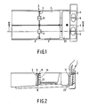
- trough-shaped detergent compartments 2 for liquid or powder detergents and care products, which are rinsed out with water in the tub of a washing machine or dishwasher.
- a rinsing chamber 23 for a fabric softener is also shown here for the sake of completeness.
- Partitions 3 are inserted into the detergent chambers 2 transversely to the rinsing direction and are provided with suction lifters 11. These partitions 3 are required when using liquid detergents and care products.
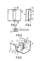
- the trough-shaped detergent chambers 2 in the area of use of the dividing walls 3 are each provided with a step 6 which is rounded off step-wise in the outlet direction. Slipping of the partition walls 3 on the bottom of the detergent chambers 2 prevent two system cams 20 which, according to FIG. 7, lie opposite the lowering 6 on the floor or one on the side walls of the trough-shaped detergent chambers 2.
- 3 fork-shaped cross pieces 24 are formed on the upper side edges of the partitions 3, each of which has a run-on slope 18, a notch 17 and a stop 19, into which notches 17, the locking cams 16 snap when the partitions 3 are inserted.
- the partition walls 3 are first clamped in a liquid-tight manner between the step-shaped depression 6 and the two system cams 20 according to FIG. 7. Then the partition 3 is pivoted in the direction of the locking cams 16 so that only the ramp slopes 18 come into contact with the locking cams 16 and then the locking cams 16 snap into the locking notches 17.
- the stops 19 prevent the partition walls 3 from pivoting further.
- the edge 12 of the partition wall 3 is provided with a U-shaped profiled seal 13 directed towards the trough-shaped detergent chambers 2 according to FIG. 5.
- the seal 13 can be clamped or injection molded.
- the suction lifter 11 is integrated into the partition 3. It consists of an intake port 9, an overflow edge 10 and an outlet 8. On the end face 7 of the suction lifter 11 there is a scale-shaped marking 14.
- the corresponding fill level 22 (FIG. 2) is easy to read by dividing walls 3 on the integrated suction lifters 11, the markings 14 are located approximately in the central region of the trough-shaped detergent chambers 2.
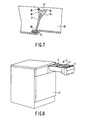
- FIG. 2 On the operator side, storage compartments 4 for the partitions 3 are provided in the detergent dispenser.
- the partitions 3 When using liquid detergents or care products, the partitions 3 are removed from the storage compartments 4 and inserted into the trough-shaped detergent chambers 2 at a predetermined location.
- the removal of the dividing walls 3 from the storage compartments 4 can be seen in FIG. 2, wherein for this purpose, conveniently shaped shapes 5 are provided on the suction lifters 11 of the dividing walls 3.
- FIG. 8 shows a washing machine 21 with a detergent dispenser 1 designed as an insert, in which the trough-shaped detergent chambers 2, the partitions 3 and storage compartments 4 are indicated.
- the detergent dispenser 1 When the detergent dispenser 1 is inserted into the washing machine, the inflowing washing water either rinses the powder from the receptacles 2 or fills the compartments 2 so that the liquid detergent or care product is rinsed and conveyed into the machine.
Abstract
Description
Die Erfindung bezieht sich auf einen Waschmitteleinspülbehälter zur Aufnahme pulverförmiger und flüssiger Wasch-und Pflegemittel bei Waschmaschinen und dergl., aus dessen wannenförmigen Waschmittelkammern die Wasch- und Pflegemittel mit Wasser in den Laugenbehälter ausgespült werden.The invention relates to a detergent dispenser for holding powdery and liquid detergents and care products in washing machines and the like. From the trough-shaped detergent compartments, the detergents and care products are rinsed out with water into the tub.
Aus der DE-OS 34 04 247 sind Waschmitteleinspülbehälter dieser Art bekannt, die wannenförmige Waschmittelkammer für die flüssigen Wasch- und Pflegemittel als lose einsetzbare Zusatzbehälter haben. Diese wannenförmigen Zusatzbehälter verteuern den Waschmitteleinspülbehälter und können bei Nichtbenutzung leicht verlorengehenDE-OS 34 04 247 detergent dispenser containers of this type are known, the trough-shaped detergent chamber for the liquid detergents and care products as loosely usable additional containers. These trough-shaped additional containers make the detergent dispenser more expensive and can easily be lost when not in use
Ferner ist ein Waschmitteleinspülbehälter mit einer Klappe mit integriertem Saugheber am hinteren Ende bekannt. Hierbei kann ein Verklumpen und Verkrusten von pulverförmigen Waschmittelresten an der am Ort verbleibenden Klappe auftreten. Da die Klappe am Ende des Waschmitteleinspülbehälters liegt, ist eine optische Füllstandskontrolle bei der Dosierung der Wasch- und Pflegemittel kaum möglich.Furthermore, a detergent dispenser with a flap with an integrated suction lifter at the rear end is known. Here, clumping and crusting of powdered detergent residues can occur on the flap that remains in place. Since the flap is at the end of the detergent dispenser, it is hardly possible to visually check the fill level when dispensing the detergent and care products.
Der Erfindung liegt die Aufgabe zugrunde, einen Waschmitteleinspülbehälter für pulverförmige Wasch- und Pflegemittel so zu gestalten, daß er mit Hilfe einfacher und billiger Mittel in eine Anzahl Waschmittelkammern für flüssige Wasch- und Pflegemittel unterteilbar ist, wobei diese Mittel von außen leicht zugängig und gut sichtbar im Waschmitteleinspülbehälter anzubringen und bei Nichtbenutzung gegebenenfalls in diesem unterzubringen sind.The invention has for its object to design a detergent dispenser for powdered detergents and care products so that it can be divided into a number of detergent compartments for liquid detergents and care products with the aid of simple and inexpensive agents, these agents being easily accessible and easily visible from the outside to be installed in the detergent dispenser and, if not used, must be accommodated in this.
Diese Aufgabe wird bei einem Waschmitteleinspülbehälter eingangs erwähnter Art gemäß der Erfindung durch quer zur Ausspülrichtung in die wannenförmigen Waschmittelkammern steckbare, mit Saughebern versehene Trennwände gelöst.This object is achieved in a detergent dispenser of the type mentioned at the outset according to the invention by means of partitions which can be plugged into the trough-shaped detergent chambers and are provided with siphons.
Die Trennwände lassen sich an gut sichtbarer Stelle in einfacher Weise in die wannenförmigen Waschmittelkammern dichtend einsetzen.The partitions can be easily inserted into the trough-shaped detergent chambers in a clearly visible place.
Um die Funktion des Saughebers zu gewährleisten, sind die wannenförmigen Waschmittelkammern im Einsatzbereich der Trennwände in Auslaufrichtung mit stufenförmig abgerundeten Absenkungen versehen, die sich zumindest im Bereich des Saugheber-Auslaufes befinden. Das durch diese Absenkungen gegebene natürliche Ablaufgefälle für Flüssigkeiten ermöglicht die Arbeitsweise des Saughebers. Zum Entleeren der durch die Trennwände abgeteilten Waschmittelkammern, wird das mit Wasch- oder Pflegemittel beschickte Kammerteil durch den Wasserzulauf so weit aufgefüllt, daß der Saugheber wirksam werden kann. Der Saugheber entleert die Kammerteile vollständig.In order to ensure the function of the suction lifter, the trough-shaped detergent chambers in the area of use of the partition walls are provided with step-like rounded depressions in the outlet direction, which are located at least in the area of the suction lifter outlet. The natural drainage gradient for liquids provided by these depressions enables the suction lifter to work. To empty the detergent compartments divided by the partitions, the chamber part charged with detergent or care agent is filled up by the water inlet to such an extent that the siphon can become effective. The siphon empties the chamber parts completely.
Vorzugsweise sind die Trennwände mit gegen die Waschmittelkammern gerichteten Randdichtungen versehen.The partition walls are preferably provided with edge seals directed against the detergent chambers.
Gemäß einer vorteilhaften Weiterentwicklung der Erfindung sind in den wannenförmigen Aufnahmen Einformungen ausgebildet, durch welche die Trennwände gehalten und geführt werden.According to an advantageous further development of the invention, recesses are formed in the trough-shaped receptacles, through which the partition walls are held and guided.
Die Trennwände können bei Nichtgebrauch griffgünstig in bedienungsseitigen Aufbewahrungsfächern des Waschmitteleinspülbehälters untergebracht sein. Diese Aufbewahrungsfächer liegen zweckmäßig im vorderen Bereich des z.B. schubladenartig ausgebildeten Waschmitteleinspül behälters. Dies hat den Vorteil, daß eine gute Sichtkontrolle gegeben ist, ob flüssiges oder pulverförmiges Waschmittel zur Verwendung kommt und daß ein Abhandenkommen der Trennwände weitestgehend vermieden wird.When not in use, the dividing walls can be conveniently accommodated in the storage compartments on the user side of the detergent dispenser. These storage compartments are expediently located in the front area of the detergent dispenser, which is designed like a drawer container. This has the advantage that there is a good visual check whether liquid or powder detergent is used and that the partition walls are largely avoided.
Für die Dosierung der flüssigen Waschmittel sind die Trennwände vorteilhaft mit Elementen zur Füllstandsanzeige ausgestattet. Mit dieser Markierung kann die Dosiermenge z.B. in ml abgelesen werden. Die eingesteckten Trennwände in der wannenförmigen Aufnahme, sind für die Bedienungsperson gut sichtbar.For the dosing of liquid detergents, the partitions are advantageously equipped with elements for level indication. With this marking, the dosing quantity e.g. can be read in ml. The inserted partitions in the trough-shaped receptacle are clearly visible to the operator.
Die wannenförmige Waschmittelkammer kann auch mehrere Einsatzmöglichkeiten für Trennwände aufweisen und damit in eine Anzahl gleicher oder verschieden großer Kammern unterteilt werden.The trough-shaped detergent chamber can also have several possible uses for partitions and can thus be divided into a number of chambers of the same or different sizes.
Ausführungsbeispiele nach der Erfindung werden anhand der Zeic hnung näher erläutert. Es zeigen:
- Fig. 1 einen als Einschub ausgebildeten Waschmitteleinspülbehälter in Draufsicht,
- Fig. 2 einen Längsschnitt durch den Waschmitteleinspülbehälter nach Fig. 1 in einer Schnittebene II-II,
- Fig. 3 eine bei dem Waschmitteleinspülbehälter nach Fig. 1 verwendete Trennwand in Vorderansicht,
- Fig. 4 einen Schnitt durch die Trennwand nach Fig. 3 entlang der Linie IV-IV,
- Fig. 5 einen Randteil der Trennwand nach Fig. 3 mit U-förmiger Dichtung in Schnittdarstellung,
- Fig. 6 eine Teilansicht der wannenförmigen Aufnahme mit Trennwand in perspektivischer Darstellung,
- Fig. 7 einen vergrößerten Längsschnitt durch die wannenförmige Aufnahme nach Fig. 6,
- Fig. 8 die Vorderansicht einer Waschmaschine mit einem als Einschub ausgebildeten Waschmitteleinspülbehälter.
- 1 is a plan view of a detergent dispenser container,
- 2 shows a longitudinal section through the detergent dispenser according to FIG. 1 in a sectional plane II-II,
- 3 is a front view of a partition used in the detergent dispenser according to FIG. 1,
- 4 shows a section through the partition according to FIG. 3 along the line IV-IV,
- 5 shows an edge part of the partition according to FIG. 3 with a U-shaped seal in a sectional view,
- 6 is a partial view of the trough-shaped receptacle with partition in a perspective view,
- 7 shows an enlarged longitudinal section through the trough-shaped receptacle according to FIG. 6,
- Fig. 8 is a front view of a washing machine with a detergent dispenser designed as an insert.
Der schubladenartig ausgebildete Waschmitteleinspülbehälter 1 ist gemäß Fig. 1 in eine Anzahl wannenförmiger Waschmittelkammern 2 für flüssige oder pulverförmige Wasch- und Pflegemittel unterteilt, welche mit Wasser in den Laugenbehälter einer Wasch- oder Geschirrspülmaschine ausgespült werden. Auch eine Spülkammer 23 für ein Weichspülmittel ist hier der Vollständigkeit halber eingezeichnet.1 is divided into a number of trough-
In die Waschmittelkammern 2 sind quer zur Ausspülrichtung Trennwände 3 eingesteckt, die mit Saughebern 11 versehen sind. Diese Trennwände 3 sind bei Verwendung von flüssigen Wasch- und Pflegemitteln erforderlich.
Nach Fig. 2 und Fig. 4 sind die wannenförmigen Waschmittelkammern 2 im Einsatzbereich der Trennwände 3 jeweils mit je einer in Auslaufrichtung stufenförmig abgerundeten Absenkung 6 versehen. Ein Verrutschen der Trennwände 3 auf dem Boden der Waschmittelkammern 2 verhindern jeweils zwei Anlagenocken 20, die nach Fig. 7 auf dem Boden oder je einem seitlich an den Seitenwandungen der wannenförmigen Waschmittelkammern 2 der Absenkung 6 gegenüberliegen.According to FIGS. 2 and 4, the trough-
Zur Halterung der Trennwände 3 befinden sich an den Seitenwandungen 15 der wannenförmigen Waschmittelkammern 2 Rastnocken 16, die mit den Trennwänden 3 zusammenwirken.To hold the
Hierzu sind an den oberen Seitenkanten der Trennwände 3 gabelförmige Querstücke 24 angeformt, die jeweils eine Anlaufschräge 18, eine Rastkerbe 17 sowie einen Anschlag 19 aufweisen, in welche Rastkerben 17, die Rastnocken 16 beim Einsetzen der Trennwände 3 einrasten. Dabei werden die Trennwände 3 zunächst zwischen der stufenförmigen Absenkung 6 und den zwei Anlagenocken 20 nach Fig. 7 flüssigkeitsdicht eingeklemmt. Anschließend wird die Trennwand 3 in Richtung auf die Rastnocken 16 so verschwenkt, daß erst die Auflaufschrägen 18 mit den Rastnocken 16 in Berührung kommen und danach die Rastnocken 16 in die Rastkerben 17 einrasten. Die Anschläge 19 verhindern ein weiteres Verschwenken der Trennwände 3.For this purpose, 3 fork-
Um eine gute Abdichtung der Trennwände 3 in den Waschmittelkammern 2 zu erreichen, ist der Rand 12 der Trennwand 3 mit einer U-förmig profilierten, gegen die wannenförmigen Waschmittelkammern 2 gerichteten Dichtung 13 nach Fig. 5 versehen. Die Dichtung 13 kann eingeklemmt oder angespritzt sein.In order to achieve a good seal of the
In die Trennwand 3 ist der Saugheber 11 integriert. Er besteht aus einem Ansaugstutzen 9 einer Überlaufkante 10 sowie einem Auslauf 8. An der Stirnfläche 7 des Saughebers 11 ist eine skalenförmige Markierung 14. Die entsprechende Füllstandshöhe 22 (Fig. 2) ist dadurch leicht abzulesen, daß die Trennwände 3, auf dessen integrierten Saughebern 11 sich die Markierungen 14 befinden, etwa im mittleren Bereich der wannenförmigen Waschmittelkammern 2 angeordnet sind.The
Bedienungsseitig sind im Waschmitteleinspülbehälter 1 Aufbewahrungsfächer 4 für die Trennwände 3 vorgesehen. Bei Verwendung flüssiger Wasch- bzw. Pflegemittel werden die Trennwände 3 aus den Aufbewahrungsfächern 4 entnommen und an vorgegebener Stelle in die wannenförmigen Waschmittelkammern 2 eingesetzt. Die Entnahme der Trennwände 3 aus den Aufbewahrungsfächern 4 ist in Fig. 2 zu sehen, wobei hierfür an den Saughebern 11 der Trennwände 3 griffgünstige Ausformungen 5 vorhanden sind.On the operator side, storage compartments 4 for the
Fig. 8 zeigt eine Waschmaschine 21 mit einem als Einschub ausgebildeten Waschmitteleinspülbehälter 1, bei dem die wannenförmigen Waschmittelkammern 2, die Trennwände 3 und Aufbewahrungsfächer 4 angedeutet sind. Wenn der Waschmitteleinspülbehälter 1 in die Waschmaschine eingeschoben ist, dann spült das zufließende Waschwasser entweder das Pulver aus den Aufnahmen 2 oder füllt die abgeteilten Kammern 2 so auf, daß die flüssigen Wasch- bzw. Pflegemittel überspült und in die Maschine gefördert wird. 8 shows a
Claims (6)
gekennzeichnet durch quer zur Ausspülrichtung in die wannenförmigen Waschmittelkammern (2) steckbare, mit Saughebern (11) versehene Trennwände (3).1. detergent dispenser for holding powdery and liquid detergents and care products in washing machines and the like, from whose trough-shaped detergent compartments the detergents and care products are rinsed with water into the tub,
characterized by partitions (3) which can be inserted into the trough-shaped detergent chambers (2) transversely to the rinsing direction and are provided with suction lifters (11).
dadurch gekennzeichnet, daß die wannenförmigen Waschmittelkammern (2) im Einsatzbereich der Trennwände (3) in Auslaufrichtung stufenförmige Absenkungen (6), zumindest im Bereich des Saugheber-Auslaufes, aufweisen.2. detergent dispenser according to claim 1,
characterized in that the trough-shaped detergent chambers (2) have step-shaped depressions (6) in the area of use of the partitions (3) in the outlet direction, at least in the area of the suction lifter outlet.
dadurch gekennzeichnet, daß die Trennwände (3) mit gegen die Waschmittelkammern gerichtete Randdichtungen (13) versehen sind.3. detergent dispenser according to claim 1 or 2,
characterized in that the partitions (3) are provided with edge seals (13) directed against the detergent chambers.
dadurch gekennzeichnet, daß die Trennwände (3) durch Einformungen, z.B. Rastnocken (16), Rastkerben (17) und Anlagenocken (20) in den wannenförmigen Waschmittelkammern (2) geführt und gehaltert sind.4. detergent dispenser according to one of claims 1 to 3,
characterized in that the partitions (3) are guided and held in the trough-shaped detergent chambers (2) by indentations, for example locking cams (16), locking notches (17) and system cams (20).
dadurch gekennzeichnet, daß die Trennwände (3) mit Elementen (14) zur Füllstandsanzeige versehen sind.5. detergent dispenser according to one of claims 1 to 4,
characterized in that the partitions (3) are provided with elements (14) for level indication.
dadurch gekennzeichnet, daß er bedienungsseitig Aufbewahrungsfächer (4) für die Trennwände (3) aufweist.6. detergent dispenser according to one of claims 1 to 5,
characterized in that it has storage compartments (4) for the partitions (3) on the operator side.
Applications Claiming Priority (2)
| Application Number | Priority Date | Filing Date | Title |
|---|---|---|---|
| DE3618275 | 1986-05-30 | ||
| DE19863618275 DE3618275A1 (en) | 1986-05-30 | 1986-05-30 | DETERGENT DISCHARGE TANK |
Publications (2)
| Publication Number | Publication Date |
|---|---|
| EP0247686A2 true EP0247686A2 (en) | 1987-12-02 |
| EP0247686A3 EP0247686A3 (en) | 1988-05-04 |
Family
ID=6301989
Family Applications (1)
| Application Number | Title | Priority Date | Filing Date |
|---|---|---|---|
| EP87200946A Withdrawn EP0247686A3 (en) | 1986-05-30 | 1987-05-20 | Detergent dispensers |
Country Status (2)
| Country | Link |
|---|---|
| EP (1) | EP0247686A3 (en) |
| DE (1) | DE3618275A1 (en) |
Cited By (5)
| Publication number | Priority date | Publication date | Assignee | Title |
|---|---|---|---|---|
| EP1350882A2 (en) * | 2002-03-14 | 2003-10-08 | Samsung Electronics Co., Ltd. | Detergent drawer for a washing machine |
| US20140352804A1 (en) * | 2011-12-21 | 2014-12-04 | BSH Bosch und Siemens Hausgeräte GmbH | Rinsing arrangement for a domestic appliance for the care of laundry items, and domestic appliance for the care of laundry items |
| CN104358076A (en) * | 2014-11-17 | 2015-02-18 | 广东格兰仕集团有限公司 | Laundry detergent box component for washing machine |
| EP3712318A4 (en) * | 2019-01-18 | 2021-03-31 | Qingdao Haier Drum Washing Machine Co., Ltd. | Detergent dispensing device |
| JP2022505729A (en) * | 2018-10-24 | 2022-01-14 | 青島海爾▲滾▼筒洗衣机有限公司 | Condensed water circulation utilization system and dryer |
Families Citing this family (1)
| Publication number | Priority date | Publication date | Assignee | Title |
|---|---|---|---|---|
| DE3735140C2 (en) * | 1987-10-16 | 1995-05-11 | Bosch Siemens Hausgeraete | Detergent dispenser for liquid and powder detergent |
Citations (3)
| Publication number | Priority date | Publication date | Assignee | Title |
|---|---|---|---|---|
| DE8215268U1 (en) * | 1982-05-26 | 1982-10-07 | Blomberg-Werke Kg, 4730 Ahlen | Dispenser for a washing machine |
| DE3404247A1 (en) * | 1984-02-07 | 1985-08-14 | Bosch-Siemens Hausgeräte GmbH, 7000 Stuttgart | Washing-agent feed device |
| DE8528094U1 (en) * | 1984-10-05 | 1985-12-12 | Zanussi Elettrodomestici S.P.A., Pordenone | Dispenser for liquid and powder detergents for a washing machine |
-
1986
- 1986-05-30 DE DE19863618275 patent/DE3618275A1/en not_active Withdrawn
-
1987
- 1987-05-20 EP EP87200946A patent/EP0247686A3/en not_active Withdrawn
Patent Citations (3)
| Publication number | Priority date | Publication date | Assignee | Title |
|---|---|---|---|---|
| DE8215268U1 (en) * | 1982-05-26 | 1982-10-07 | Blomberg-Werke Kg, 4730 Ahlen | Dispenser for a washing machine |
| DE3404247A1 (en) * | 1984-02-07 | 1985-08-14 | Bosch-Siemens Hausgeräte GmbH, 7000 Stuttgart | Washing-agent feed device |
| DE8528094U1 (en) * | 1984-10-05 | 1985-12-12 | Zanussi Elettrodomestici S.P.A., Pordenone | Dispenser for liquid and powder detergents for a washing machine |
Cited By (11)
| Publication number | Priority date | Publication date | Assignee | Title |
|---|---|---|---|---|
| EP1350882A2 (en) * | 2002-03-14 | 2003-10-08 | Samsung Electronics Co., Ltd. | Detergent drawer for a washing machine |
| EP1350882A3 (en) * | 2002-03-14 | 2004-01-28 | Samsung Electronics Co., Ltd. | Detergent drawer for a washing machine |
| US7093467B2 (en) | 2002-03-14 | 2006-08-22 | Samsung Electronics Co., Ltd. | Washing machine having detergent supply apparatus |
| US20140352804A1 (en) * | 2011-12-21 | 2014-12-04 | BSH Bosch und Siemens Hausgeräte GmbH | Rinsing arrangement for a domestic appliance for the care of laundry items, and domestic appliance for the care of laundry items |
| US9493901B2 (en) * | 2011-12-21 | 2016-11-15 | Bsh Hausgerate Gmbh | Rinsing arrangement for a domestic appliance for the care of laundry items, and domestic appliance for the care of laundry items |
| CN104358076A (en) * | 2014-11-17 | 2015-02-18 | 广东格兰仕集团有限公司 | Laundry detergent box component for washing machine |
| JP2022505729A (en) * | 2018-10-24 | 2022-01-14 | 青島海爾▲滾▼筒洗衣机有限公司 | Condensed water circulation utilization system and dryer |
| EP3872252A4 (en) * | 2018-10-24 | 2022-07-20 | Qingdao Haier Drum Washing Machine Co., Ltd. | Detergent box and washing machine comprising same |
| EP3712318A4 (en) * | 2019-01-18 | 2021-03-31 | Qingdao Haier Drum Washing Machine Co., Ltd. | Detergent dispensing device |
| JP2022517153A (en) * | 2019-01-18 | 2022-03-07 | 青島海爾滾筒洗衣机有限公司 | Detergent injection device |
| US11414807B2 (en) | 2019-01-18 | 2022-08-16 | Qingdao Haier Drum Washing Machine Co., Ltd. | Detergent dispensing device |
Also Published As
| Publication number | Publication date |
|---|---|
| EP0247686A3 (en) | 1988-05-04 |
| DE3618275A1 (en) | 1987-12-03 |
Similar Documents
| Publication | Publication Date | Title |
|---|---|---|
| DE3608619C2 (en) | ||
| EP1808520B1 (en) | Treatment agents dispensing device for use in a washing machine | |
| DE60201524T2 (en) | DETERGENT DISPENSER FOR DISHWASHER | |
| EP2342377A1 (en) | Automatically controlled washing machine having a detergent inlet device | |
| EP0940509B1 (en) | Cleaning device | |
| DE3608620C2 (en) | ||
| EP0247686A2 (en) | Detergent dispensers | |
| DE102013226985B4 (en) | Detergent addition with simplified closing function | |
| EP3247252B1 (en) | Cleaner cartridge, cleaning agent dosing system and household dishwasher | |
| DE8528094U1 (en) | Dispenser for liquid and powder detergents for a washing machine | |
| DE102010003776A1 (en) | Dishwasher, particularly domestic dishwasher, has washing chamber, which is limited by walls and door, and has cartridge with multiple storage chambers for cleaning agent | |
| DE19935728C2 (en) | Detergent tablets container | |
| DE10028630B4 (en) | Integrated dispenser for detergent and rinse aid for a dishwasher | |
| EP1345526B2 (en) | Device for improving the drying performance of a dishwasher | |
| DE3805084A1 (en) | HOUSEHOLD DISHWASHER | |
| DE3623027A1 (en) | Feeding device in dishwashers for a cleaning agent, in particular pulverulent cleaning agent | |
| EP0553058B1 (en) | Dishwasher or washing machine with a dosing device | |
| WO2002039871A1 (en) | Adapter for a dish basket of a dishwasher | |
| DE19859984B4 (en) | Detergent dispenser for washing machines | |
| DE3607632C2 (en) | ||
| DE19852205C2 (en) | Detergent dispenser | |
| DE19728105A1 (en) | Detergent flushing chamber for washing machines | |
| DE7933519U1 (en) | Dispensing device for detergents or detergents in dishwashers or washing machines | |
| WO2023046444A1 (en) | Domestic dishwasher | |
| DE102021206589A1 (en) | Insert, modular system, detergent dosing unit and water-bearing household appliance |
Legal Events
| Date | Code | Title | Description |
|---|---|---|---|
| PUAI | Public reference made under article 153(3) epc to a published international application that has entered the european phase |
Free format text: ORIGINAL CODE: 0009012 |
|
| AK | Designated contracting states |
Kind code of ref document: A2 Designated state(s): DE ES FR GB IT SE |
|
| PUAL | Search report despatched |
Free format text: ORIGINAL CODE: 0009013 |
|
| AK | Designated contracting states |
Kind code of ref document: A3 Designated state(s): DE ES FR GB IT SE |
|
| STAA | Information on the status of an ep patent application or granted ep patent |
Free format text: STATUS: THE APPLICATION IS DEEMED TO BE WITHDRAWN |
|
| 18D | Application deemed to be withdrawn |
Effective date: 19890521 |
|
| RIN1 | Information on inventor provided before grant (corrected) |
Inventor name: SPERLING, HORST Inventor name: HOFFMANN, ALFRED |