EP0247504A2 - Procédé de préparation de gaz contenant de l'hydrogène et du monoxyde de carbone à partir de combustibles solides - Google Patents
Procédé de préparation de gaz contenant de l'hydrogène et du monoxyde de carbone à partir de combustibles solides Download PDFInfo
- Publication number
- EP0247504A2 EP0247504A2 EP87107304A EP87107304A EP0247504A2 EP 0247504 A2 EP0247504 A2 EP 0247504A2 EP 87107304 A EP87107304 A EP 87107304A EP 87107304 A EP87107304 A EP 87107304A EP 0247504 A2 EP0247504 A2 EP 0247504A2
- Authority
- EP
- European Patent Office
- Prior art keywords
- return line
- gas
- reactor
- solid
- fluidized bed
- Prior art date
- Legal status (The legal status is an assumption and is not a legal conclusion. Google has not performed a legal analysis and makes no representation as to the accuracy of the status listed.)
- Granted
Links
Images
Classifications
-
- C—CHEMISTRY; METALLURGY
- C10—PETROLEUM, GAS OR COKE INDUSTRIES; TECHNICAL GASES CONTAINING CARBON MONOXIDE; FUELS; LUBRICANTS; PEAT
- C10J—PRODUCTION OF PRODUCER GAS, WATER-GAS, SYNTHESIS GAS FROM SOLID CARBONACEOUS MATERIAL, OR MIXTURES CONTAINING THESE GASES; CARBURETTING AIR OR OTHER GASES
- C10J3/00—Production of combustible gases containing carbon monoxide from solid carbonaceous fuels
- C10J3/46—Gasification of granular or pulverulent flues in suspension
- C10J3/54—Gasification of granular or pulverulent fuels by the Winkler technique, i.e. by fluidisation
-
- C—CHEMISTRY; METALLURGY
- C10—PETROLEUM, GAS OR COKE INDUSTRIES; TECHNICAL GASES CONTAINING CARBON MONOXIDE; FUELS; LUBRICANTS; PEAT
- C10J—PRODUCTION OF PRODUCER GAS, WATER-GAS, SYNTHESIS GAS FROM SOLID CARBONACEOUS MATERIAL, OR MIXTURES CONTAINING THESE GASES; CARBURETTING AIR OR OTHER GASES
- C10J3/00—Production of combustible gases containing carbon monoxide from solid carbonaceous fuels
- C10J3/46—Gasification of granular or pulverulent flues in suspension
- C10J3/48—Apparatus; Plants
- C10J3/482—Gasifiers with stationary fluidised bed
-
- C—CHEMISTRY; METALLURGY
- C10—PETROLEUM, GAS OR COKE INDUSTRIES; TECHNICAL GASES CONTAINING CARBON MONOXIDE; FUELS; LUBRICANTS; PEAT
- C10J—PRODUCTION OF PRODUCER GAS, WATER-GAS, SYNTHESIS GAS FROM SOLID CARBONACEOUS MATERIAL, OR MIXTURES CONTAINING THESE GASES; CARBURETTING AIR OR OTHER GASES
- C10J3/00—Production of combustible gases containing carbon monoxide from solid carbonaceous fuels
- C10J3/46—Gasification of granular or pulverulent flues in suspension
- C10J3/48—Apparatus; Plants
- C10J3/52—Ash-removing devices
- C10J3/523—Ash-removing devices for gasifiers with stationary fluidised bed
-
- C—CHEMISTRY; METALLURGY
- C10—PETROLEUM, GAS OR COKE INDUSTRIES; TECHNICAL GASES CONTAINING CARBON MONOXIDE; FUELS; LUBRICANTS; PEAT
- C10J—PRODUCTION OF PRODUCER GAS, WATER-GAS, SYNTHESIS GAS FROM SOLID CARBONACEOUS MATERIAL, OR MIXTURES CONTAINING THESE GASES; CARBURETTING AIR OR OTHER GASES
- C10J3/00—Production of combustible gases containing carbon monoxide from solid carbonaceous fuels
- C10J3/46—Gasification of granular or pulverulent flues in suspension
- C10J3/54—Gasification of granular or pulverulent fuels by the Winkler technique, i.e. by fluidisation
- C10J3/56—Apparatus; Plants
-
- C—CHEMISTRY; METALLURGY
- C10—PETROLEUM, GAS OR COKE INDUSTRIES; TECHNICAL GASES CONTAINING CARBON MONOXIDE; FUELS; LUBRICANTS; PEAT
- C10K—PURIFYING OR MODIFYING THE CHEMICAL COMPOSITION OF COMBUSTIBLE GASES CONTAINING CARBON MONOXIDE
- C10K1/00—Purifying combustible gases containing carbon monoxide
- C10K1/02—Dust removal
- C10K1/026—Dust removal by centrifugal forces
-
- C—CHEMISTRY; METALLURGY
- C10—PETROLEUM, GAS OR COKE INDUSTRIES; TECHNICAL GASES CONTAINING CARBON MONOXIDE; FUELS; LUBRICANTS; PEAT
- C10J—PRODUCTION OF PRODUCER GAS, WATER-GAS, SYNTHESIS GAS FROM SOLID CARBONACEOUS MATERIAL, OR MIXTURES CONTAINING THESE GASES; CARBURETTING AIR OR OTHER GASES
- C10J2200/00—Details of gasification apparatus
- C10J2200/15—Details of feeding means
- C10J2200/152—Nozzles or lances for introducing gas, liquids or suspensions
-
- C—CHEMISTRY; METALLURGY
- C10—PETROLEUM, GAS OR COKE INDUSTRIES; TECHNICAL GASES CONTAINING CARBON MONOXIDE; FUELS; LUBRICANTS; PEAT
- C10J—PRODUCTION OF PRODUCER GAS, WATER-GAS, SYNTHESIS GAS FROM SOLID CARBONACEOUS MATERIAL, OR MIXTURES CONTAINING THESE GASES; CARBURETTING AIR OR OTHER GASES
- C10J2200/00—Details of gasification apparatus
- C10J2200/15—Details of feeding means
- C10J2200/158—Screws
-
- C—CHEMISTRY; METALLURGY
- C10—PETROLEUM, GAS OR COKE INDUSTRIES; TECHNICAL GASES CONTAINING CARBON MONOXIDE; FUELS; LUBRICANTS; PEAT
- C10J—PRODUCTION OF PRODUCER GAS, WATER-GAS, SYNTHESIS GAS FROM SOLID CARBONACEOUS MATERIAL, OR MIXTURES CONTAINING THESE GASES; CARBURETTING AIR OR OTHER GASES
- C10J2300/00—Details of gasification processes
- C10J2300/18—Details of the gasification process, e.g. loops, autothermal operation
- C10J2300/1807—Recycle loops, e.g. gas, solids, heating medium, water
-
- Y—GENERAL TAGGING OF NEW TECHNOLOGICAL DEVELOPMENTS; GENERAL TAGGING OF CROSS-SECTIONAL TECHNOLOGIES SPANNING OVER SEVERAL SECTIONS OF THE IPC; TECHNICAL SUBJECTS COVERED BY FORMER USPC CROSS-REFERENCE ART COLLECTIONS [XRACs] AND DIGESTS
- Y10—TECHNICAL SUBJECTS COVERED BY FORMER USPC
- Y10S—TECHNICAL SUBJECTS COVERED BY FORMER USPC CROSS-REFERENCE ART COLLECTIONS [XRACs] AND DIGESTS
- Y10S48/00—Gas: heating and illuminating
- Y10S48/04—Powdered fuel injection
Definitions
- the invention relates to a process for producing hydrogen and carbon monoxide-containing gases from solid fuels at elevated pressure in a fluidized bed using gasifying agents, a fixed bed of solid gasification residues from which the solid gasification residues are drawn off possibly being located below the fluidized bed, and A post-gasification space is arranged above the fluidized bed and the synthesis gas generated is drawn off from the post-gasification space and passed through a separator in which at least some of the entrained solid particles are separated and returned to the fluidized bed via a return line, while the synthesis gas in the at least pre-cleaned state passes the separator leaves.
- a gasification reactor which has a lower, conical part in which the fuel to be gasified is whirled up by the gasification agent.
- the resulting fluidized bed within which the fuel particles are in constant motion, has a lower and an upper limit, which are usually not sharp.
- the lower limit is formed by the fixed bed, which consists of finer and coarser, possibly sintered solid gasification residues.
- the axis is withdrawn from the reactor.
- the solid particles separated in the cyclone still contain so much carbon that it is worth returning them to the reactor.
- an increased supply of gasification agents into the fluidized bed an operating state can even be reached which is referred to as a "circulating fluidized bed".
- An upper boundary of the fluidized bed is no longer formed. Rather, so much gasification agent is supplied that the majority of the fuel particles enter the post-gasification chamber and from there into the separator and must therefore be recycled anyway if a sufficient degree of gasification is to be achieved.
- the return line through which the particulate matter deposited in the cyclone is returned to the reactor extends between the cyclone, generally between the lower part thereof, and the reactor, the arrangement normally being such that the return line is in the region of the fluidized bed, that is, in the lower region of the reactor opens into this.
- the return line runs obliquely at least in some areas, that is to say in one acute angle to the vertical. In any case, the interior of the reactor, the separator and the return line form a coherent system.
- the risk that the solids in the return line get stuck therein, with the result that after a short time the solid accumulating in the return line reaches the separator is particularly due to the fact that the return line has a small diameter in relation to its length .
- the length will generally be determined by the distance to be bridged between the separator and the region of the fluidized bed reactor into which the solid to be returned is to be brought.
- An increase in the diameter of the return line, which would counteract the risk of blockages occurring, is ruled out, since this would undesirably influence the pressure and flow conditions in the overall device, possibly to a point at which the system does not more works.
- the invention has for its object to improve the method of the type described in the introduction so that, regardless of the amount of solid particles to be returned from the separator into the reactor, proper continuous operation of the gasification reactor is ensured.
- the relatively small cross-section of the return line it should be ensured under all operational circumstances that the solid particles to be returned can be returned to the reactor in a controllable manner depending on the particular circumstances, that is to say on the gasification pressure, quantity and time.
- the invention proposes that gas be introduced in pulses in the return line at least at one point to loosen up the solid particles therein.
- a procedure has been found to be particularly expedient in which gas is blown into the return line at a plurality of points spaced apart in the longitudinal direction of the return line, these points should be arranged in the region in which the solid particles to be returned accumulate. It is therefore the area which is adjacent to the reactor or the fluidized bed located therein.
- Some of the gas streams blown into the return line at different points can be blown in continuously.
- the pulsed blowing of at least some of the gas streams into the return line also has the advantage that less gas is used to achieve the same effect. This is also important because the return line is too large quantity of gas blown in, which at least predominantly flows upwards towards the cyclone, reduces the separating capacity of the cyclone.
- An operating mode has proven to be expedient in which the gas is blown into the return line at the lowest, i.e. the mouth of the return line into the reactor, and the gas is blown into the return line intermittently, i.e. in pulses, at all other locations above it.
- a mode of operation in which the pulse-like injection of the gas at the injection points is at least temporarily offset is particularly advantageous in such a way that from two injection points at a distance in the longitudinal direction of the return line, the injection begins earlier and possibly also at the injection point positioned closer to the reactor ends earlier than at the injection point positioned further away from the reactor. It is thereby achieved that the solid column located in the return line progresses from bottom to top, i.e. against the direction of flow of the solid in the return line, a loosening, which leads to the fact that below the area of the solid column loosened by a gas pulse at a certain position the solid has also already been loosened, possibly already drained off.
- the flow process within the return line can be influenced well in terms of quantity and time, so that the gas pulses can be controlled, in particular whose temporal offset can also be used to determine the rate at which the solid flows out of the return line into the reactor.
- the amount of gas to be blown in may depend on the amount of the solid present in the return line or of the solid to be returned to the reactor.
- the number of gas pulses can also depend on the amount of the solid in the return line or the solid to be returned to the reactor.
- the duration of a pulse can be 0.1 to 2 s, preferably 1 s. In general, it is expedient to provide a pause between two successive pulses which lasts 1 s, preferably 0.1 s.
- the time shift between the pulses of two adjacent blowing points can be so great that the pulse on the in each case in the chronological order second blowing point only begins after the pulse has ended in the blowing point located before.
- the amount of gas injected or the number of gas pulses can be controlled as a function of the temperature in the return line.
- Inert gas e.g. B. Co2 or nitrogen or recycled process gas can be used.
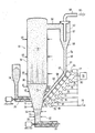
- the gasification process for the production of a product gas takes place in a reactor 10, in its lower, conically tapering area 12, the fluidized bed 14 is located.
- the conical region is adjoined at the top by a cylindrical region 16 which contains the post-gasification zone 18.
- the reactor 10 merges into a short shaft 20, at the end of which a conveyor and cooling screw 22 is arranged.
- a conveyor and cooling screw 22 is arranged.
- the shaft 20 and the worm 22 the solid gasification residues deducted, which predominantly contain ash and collect below the fluidized bed 14 in a fixed bed 24.
- the solid fuel to be gasified is introduced into the reactor 10 from a reservoir 28 by a screw 26. In the embodiment shown in the drawing, the solid fuel enters the latter below the upper limit 30 of the fluidized bed 14.
- the fuel can e.g. B. pre-dried lignite, which has a water content of 12-18% and a grain size between 0 and 5 mm.
- other carbon-containing fuels can also be used, e.g. Peat or coals that are more coalized than brown coal.
- the reactor 10 is provided with a plurality of feed lines for gaseous media, which serve as gasifying agents.
- the leads 32 located at the bottom open into the shaft 20 and serve to supply a gaseous medium to loosen the fixed bed 24.
- This medium can be an endothermic gasifying agent, for example steam or CO2, but also an inert medium, for. B. nitrogen act.
- nozzles are provided for the supply of gasification agent in planes which are at vertical distances from one another.
- leads 34, 36 in the Lower levels are preferably supplied with a gasifying agent which brings about endothermic reactions.
- Oxygen-containing gasification agents are supplied in the feed lines 40, 41.
- feed lines 44, 45 and 46 open into the after-reaction space 18. Gasification agents which bring about exothermic and endothermic reactions are normally introduced into the after-reaction space 18 via these feed lines.
- the fuel to be gasified is introduced into the reactor 10 by the screw 26 in the region of the fluidized bed 14.
- the fuel particles are fluidized by the gasification agents, the degassing products, the vapor produced by the evaporation of the water contained in the fuel and the reaction products.
- the very small, almost dust-like components of the solid fuel introduced into the fluidized bed are entrained relatively quickly by the gas flowing upward through the upper boundary of the Wibel bed 30 into the after-reaction space 18, in which they are largely converted.
- the extent to which gasification agents are fed through the feed lines 44, 45, 46 into the post-reaction space 18 depends in particular on the amount of solid carbon to be converted in the post-reaction space 18.
- the heavy particles within the fluidized bed 14 sink through the latter and thus reach the fixed bed 24.
- These heavier particles can be coarser, predominantly carbon-containing particles that are too large for the fluidized bed to move from below to the bottom gas flowing through the top could be carried.
- such particles sediment down through the fluidized bed 14 onto the fixed bed 24, the weight of which is too high in relation to the grain size. It can be both carbon-containing particles with a high ash content and particles that consist exclusively of non-gasifiable substances.
- the product gas 65 generated in the reactor 10 is withdrawn through a line 50 extending from the reactor 10 near the upper end thereof and, after pre-cleaning in a cyclone 52, downstream devices, e.g. B. supplied for gas cleaning.
- the solid particles separated in the cyclone 52 which generally still contain carbon, pass via the lower outlet 66 of the cyclone into a return line 69, the lower, obliquely extending section 62 end 62 of which is connected to the reactor 10 in the region of the fluidized bed 14.
- the gas 65 cleaned from the separated solid particles leaves cyclone 52 through a dip tube 67 via a line 68.
- the return line 69 for the solid particles deposited in the cyclone 52 opens into the reactor 10 at about the level of the screw 26.
- the solid particles flow downward from the lower region of the cyclone 66 into the return line 69, the cross section of which in the region 62 between the mouth 60 into the reactor 10 and about level 61 is filled by the solid particles.
- the column of solid particles thus formed within the return line 69 constitutes a barrier which prevents solid particles and gas from the reactor 10 from passing through the return line 69 directly into the area of the separator 52 designed as a cyclone.
- the return line 69 has a relatively small cross-section and, moreover, the pressure prevailing in the area of the cyclone 52 is noticeably lower than the pressure in the fluidized bed 14, so that a pressure gradient which counteracts gravity between the mouth 60 of the return line 69 into the reactor 10 on the one hand and the On the other hand, cyclone 52 exists, without special measures there is no guarantee that as much solid particles from the return line 69 will enter the reactor 10 over longer periods of time as will pass from the cyclone 52 into the return line above.
- the small cross-section of the return line 69 means that the particles contained therein can settle, so that even if a solid column formed in the return line 69, the latter Height and thus their weight is sufficient to compensate for the pressure drop, a proper and undisturbed flow of the solid particles forming this column into the reactor 10 would not be guaranteed.
- nozzles 81 for a gaseous medium opening into the return line 69 are provided. These nozzles 81 are arranged at intervals from one another in the longitudinal direction of the return line 69.
- You are fed via intermediate control valves 70 to 77 from a common pressure medium source 78 with a gas, which may be, for example, CO2 or recycled product gas, which is branched off from the gas stream 65 at a suitable point.
- the control valves 71-77 are actuated by a common controller 79, to which they are connected via a line 80.
- the pressure level of the gas 78 will be somewhat higher than the pressure level in the fluidized bed 14.
- the controller 79 controls the individual valves 71 - 77 and thereby briefly releases a gas flow of a certain amount, which flows through the nozzles 81 into the lower region of the pulse Return line 69 arrives. It can be done in such a way that the valves 70-77 successively cause a short-term gas pulse such that a gas pulse is first passed through the valve 70 or the associated nozzle 81 into the mouth 60 of the return line 69 and then gas pulses are delayed by the others Valves in the Return line 69 are introduced, the time interval from the first gas pulse caused by the valve 70 increasing with increasing distance of the respective valve from the first valve 70.
- valve 70 it is also possible to allow a longer pause to occur after actuation of the last valve 77 before the next pulse cycle begins by actuation of the valve 70. This depends on the amount of solid that comes out of the cyclone 52 enters the return line 69 and thus of the speed at which the solid particles from the return line 69 have to be introduced into the reactor 10. It is also possible, if necessary, not to allow the pulse cycle to run over the entire number of valves 70-77 present, but rather, for example, to only give gas pulses into return line 69 through valves 70-75. How the process is carried out depends on the particular circumstances, in particular the amount of solids collected in the return line 69 per unit of time.
- the individual valves 70-77 can be actuated in a simple manner via the controller 79, to which the temperature sensors 57-59 detecting the temperature in the return line 69 are assigned, which are assigned to the area of the return line 69 in which the nozzles 81 of the valves 70 -77 are.
- a temperature level is established within the latter which is not substantially below the temperature level within the fluidized bed 14 and usually in the range between 800 and 1000 ° C. If the return of the solid slows down, a direct drop in the temperature level to lower values can be determined at the temperature measuring points 57-59. This change in temperature shows that the return of the solid from line 69 into fluidized bed 14 is too slow.
- the nozzles 81 consist of customary, heat-resistant materials. Commercially available pneumatic switching valves can be used for valves 70 - 77. It is expedient to arrange them at equally large distances from and along the return line 69, it being possible to provide 1-3 nozzles / m of the return line.
- the nozzles 81 are normally predominantly in the area of the return be arranged line that does not run vertically.
- the diameter of the return line 69 can be 20 cm, for example.
- the diameter of the return line 69 can be 20 cm, for example.
- the amount of gas to be blown into the return line is small.
- the quantitative ratio between this gas to be blown in and the product gas produced in the gasification reactor can be approximately 2: 500.
Landscapes
- Chemical & Material Sciences (AREA)
- Engineering & Computer Science (AREA)
- Combustion & Propulsion (AREA)
- Oil, Petroleum & Natural Gas (AREA)
- Organic Chemistry (AREA)
- Chemical Kinetics & Catalysis (AREA)
- General Chemical & Material Sciences (AREA)
- Devices And Processes Conducted In The Presence Of Fluids And Solid Particles (AREA)
- Industrial Gases (AREA)
- Fluidized-Bed Combustion And Resonant Combustion (AREA)
Applications Claiming Priority (2)
| Application Number | Priority Date | Filing Date | Title |
|---|---|---|---|
| DE3617802 | 1986-05-27 | ||
| DE19863617802 DE3617802A1 (de) | 1986-05-27 | 1986-05-27 | Verfahren zur herstellung von wasserstoff und kohlenmonoxid enthaltenen gasen aus festen brennstoffen |
Publications (3)
| Publication Number | Publication Date |
|---|---|
| EP0247504A2 true EP0247504A2 (fr) | 1987-12-02 |
| EP0247504A3 EP0247504A3 (en) | 1988-04-06 |
| EP0247504B1 EP0247504B1 (fr) | 1990-10-03 |
Family
ID=6301727
Family Applications (1)
| Application Number | Title | Priority Date | Filing Date |
|---|---|---|---|
| EP87107304A Expired - Lifetime EP0247504B1 (fr) | 1986-05-27 | 1987-05-19 | Procédé de préparation de gaz contenant de l'hydrogène et du monoxyde de carbone à partir de combustibles solides |
Country Status (8)
| Country | Link |
|---|---|
| US (1) | US4852994A (fr) |
| EP (1) | EP0247504B1 (fr) |
| CN (1) | CN1011417B (fr) |
| AU (1) | AU594463B2 (fr) |
| DE (2) | DE3617802A1 (fr) |
| ES (1) | ES2017959B3 (fr) |
| FI (1) | FI86075C (fr) |
| GR (1) | GR3001127T3 (fr) |
Families Citing this family (12)
| Publication number | Priority date | Publication date | Assignee | Title |
|---|---|---|---|---|
| US4976755A (en) * | 1989-10-19 | 1990-12-11 | Shell Oil Company | Stripping and depressurization of solids and gas mixture |
| DE4202980A1 (de) * | 1992-02-03 | 1993-08-05 | Babcock Energie Umwelt | Verfahren und vorrichtung zur vergasung von brennbaren materialien |
| PL172755B1 (pl) * | 1992-05-08 | 1997-11-28 | Victoria Elect Commission | Sposób gazyfikacji rozdrobnionego paliwa weglowego w postaci stalej, o duzej zawartosci wilgoci oraz urzadzenie do stosowania tego sposobu PL PL PL PL PL PL PL PL |
| DE4340459C1 (de) * | 1993-11-27 | 1995-05-18 | Rheinische Braunkohlenw Ag | Verfahren zum Betreiben eines Wirbelschichtreaktors zum Vergasen von kohlenstoffhaltigen Einsatzstoffen |
| DE19548324C2 (de) * | 1994-12-23 | 1998-08-06 | Rheinische Braunkohlenw Ag | Verfahren zum Vergasen von kohlenstoffhaltigen Feststoffen in der Wirbelschicht sowie dafür verwendbarer Vergaser |
| EP0780459A3 (fr) | 1995-12-22 | 1997-09-10 | Rheinische Braunkohlenw Ag | Procédé pour la gazéification de solides contenant du carbone en fluidisé et producteur de gaz correspondant |
| FI120770B (fi) * | 2001-10-02 | 2010-02-26 | Valtion Teknillinen | Menetelmä ja laitteisto polttoaineen kaasuttamiseksi leijukerrosreaktorissa |
| US6851896B1 (en) * | 2003-09-18 | 2005-02-08 | Kerr-Mcgee Chemical, Llc | Fluid barriers |
| CN102911741B (zh) * | 2012-10-18 | 2013-12-25 | 东南大学 | 循环流化床煤气化的装置 |
| EP2862914A1 (fr) * | 2013-10-16 | 2015-04-22 | Syncraft Engineering GmbH | Procédé de réglage destiné au fonctionnement d'un gazéificateur à lit mobile et d'un réacteur à lit mobile |
| DE102017219783A1 (de) * | 2017-11-07 | 2019-05-09 | Thyssenkrupp Ag | Vorrichtung und Verfahren zum Vergasen von Einsatzstoffen und zum Bereitstellen von Synthesegas sowie Verwendung |
| GB201906310D0 (en) * | 2019-05-03 | 2019-06-19 | Schenck Process Uk Ltd | Material conveying apparatus with shut down valves |
Citations (3)
| Publication number | Priority date | Publication date | Assignee | Title |
|---|---|---|---|---|
| US3840353A (en) * | 1971-07-30 | 1974-10-08 | A Squires | Process for gasifying granulated carbonaceous fuel |
| FR2277141A1 (fr) * | 1974-07-03 | 1976-01-30 | Mitsubishi Heavy Ind Ltd | Appareil pour gazeifier du charbon et autres matieres |
| EP0173782A1 (fr) * | 1983-12-23 | 1986-03-12 | Creusot-Loire | Procédé de traitement de matiéres |
Family Cites Families (18)
| Publication number | Priority date | Publication date | Assignee | Title |
|---|---|---|---|---|
| DE1074803B (de) * | 1960-02-04 | Badische Anilin- &. Soda-Fabrik Aktiengesellschaft, Ludwigshafen/Rhein | Verfahren zur Brenngaserzeugung durch Vergasen feinzerteilter fester oder flüssiger Brennstoffe und/oder durch Spalten gasförmiger Brennstoffe in einer Wirbelschicht | |
| US2671721A (en) * | 1946-08-03 | 1954-03-09 | Standard Oil Dev Co | Production of industrial gas comprising carbon monoxide and hydrogen |
| US2739845A (en) * | 1951-01-26 | 1956-03-27 | Union Oil Co | Conveyance of granular solids |
| DE974634C (de) * | 1951-03-03 | 1961-03-09 | Ruhrgas Ag | Verfahren zur Brennglaserzeugung durch Vergasen eines feinkoernigen Brennstoffes |
| DE1017314B (de) * | 1953-10-09 | 1957-10-10 | Basf Ag | Verfahren zur Erzeugung von Brenngasen aus staubfoermigen bis grobkoernigen Brennstoffen |
| US2873145A (en) * | 1956-06-11 | 1959-02-10 | Exxon Research Engineering Co | Circulating finely divided solids |
| DE1174301B (de) * | 1960-04-01 | 1964-07-23 | Huetten Und Bergwerke Rheinhau | Vorrichtung zur Kreislauffuehrung von Abgasen und aus diesen ausgeschiedener Feststoffe beim Betrieb eines Wirbelschichtofens |
| US3160443A (en) * | 1962-10-23 | 1964-12-08 | Western Electric Co | Apparatus for pneumatically conveying articles |
| US3537755A (en) * | 1968-09-30 | 1970-11-03 | Allied Chem | Charging coke oven with hot coarsely comminuted coal |
| DE2015791A1 (de) * | 1970-04-02 | 1971-10-21 | Rheinische Braunkohlenwerke AG, 5000 Köln, Wenzel, Prof Dr Ing Werner, 5 lOO Aachen | Verfahren und Vorrichtung für den Transport von Kornhaufwerken in Rohren |
| IT974658B (it) * | 1972-10-25 | 1974-07-10 | Rusterholz Otto | Procedimento e dispositivo per il trasporto di un materiale solido incoerente mediante un fluido sot to pressione particolarmente per impianti di trasporto pneumatico |
| US3874739A (en) * | 1973-08-07 | 1975-04-01 | Exxon Research Engineering Co | Method and apparatus for the transfer of entrained solids |
| US3957457A (en) * | 1973-10-26 | 1976-05-18 | Squires Arthur M | Gasifying coal or coke and discharging ash agglomerates |
| DE2524540C2 (de) * | 1975-06-03 | 1986-04-24 | Metallgesellschaft Ag, 6000 Frankfurt | Verfahren zur Durchführung endothermer Prozesse |
| US4017272A (en) * | 1975-06-05 | 1977-04-12 | Bamag Verfahrenstechnik Gmbh | Process for gasifying solid carbonaceous fuel |
| US4185942A (en) * | 1977-10-06 | 1980-01-29 | The United States Of America As Represented By The Administrator Of The United States Environmental Protection Agency | Material transfer system |
| US4457289A (en) * | 1982-04-20 | 1984-07-03 | York-Shipley, Inc. | Fast fluidized bed reactor and method of operating the reactor |
| FI75505C (fi) * | 1985-01-11 | 1988-07-11 | Ahlstroem Oy | Foerfarande och anordning foer avskiljning av fast material ur roekgaserna fraon en reaktor med cirkulerande baedd. |
-
1986
- 1986-05-27 DE DE19863617802 patent/DE3617802A1/de active Granted
-
1987
- 1987-05-19 EP EP87107304A patent/EP0247504B1/fr not_active Expired - Lifetime
- 1987-05-19 ES ES87107304T patent/ES2017959B3/es not_active Expired - Lifetime
- 1987-05-19 DE DE8787107304T patent/DE3765311D1/de not_active Expired - Lifetime
- 1987-05-22 AU AU73314/87A patent/AU594463B2/en not_active Ceased
- 1987-05-22 US US07/053,447 patent/US4852994A/en not_active Expired - Lifetime
- 1987-05-26 FI FI872321A patent/FI86075C/fi not_active IP Right Cessation
- 1987-05-27 CN CN87103895A patent/CN1011417B/zh not_active Expired
-
1990
- 1990-11-29 GR GR90400986T patent/GR3001127T3/el unknown
Patent Citations (3)
| Publication number | Priority date | Publication date | Assignee | Title |
|---|---|---|---|---|
| US3840353A (en) * | 1971-07-30 | 1974-10-08 | A Squires | Process for gasifying granulated carbonaceous fuel |
| FR2277141A1 (fr) * | 1974-07-03 | 1976-01-30 | Mitsubishi Heavy Ind Ltd | Appareil pour gazeifier du charbon et autres matieres |
| EP0173782A1 (fr) * | 1983-12-23 | 1986-03-12 | Creusot-Loire | Procédé de traitement de matiéres |
Also Published As
| Publication number | Publication date |
|---|---|
| FI872321A0 (fi) | 1987-05-26 |
| DE3617802A1 (de) | 1987-12-03 |
| AU594463B2 (en) | 1990-03-08 |
| EP0247504A3 (en) | 1988-04-06 |
| EP0247504B1 (fr) | 1990-10-03 |
| CN1011417B (zh) | 1991-01-30 |
| ES2017959B3 (es) | 1991-03-16 |
| GR3001127T3 (en) | 1992-06-25 |
| FI86075C (fi) | 1992-07-10 |
| CN87103895A (zh) | 1987-12-16 |
| US4852994A (en) | 1989-08-01 |
| AU7331487A (en) | 1987-12-03 |
| DE3617802C2 (fr) | 1992-09-10 |
| FI872321A (fi) | 1987-11-28 |
| DE3765311D1 (de) | 1990-11-08 |
| FI86075B (fi) | 1992-03-31 |
Similar Documents
| Publication | Publication Date | Title |
|---|---|---|
| DE69603173T2 (de) | Ablagerungsvorrichtung für eine flüssigkeit, gas und partikelförmiges material enthaltendes fluidum, sowie eine mit einer solchen vorrichtung ausgerüsteten reinigungsanlage und reinigungsverfahren | |
| EP0247504B1 (fr) | Procédé de préparation de gaz contenant de l'hydrogène et du monoxyde de carbone à partir de combustibles solides | |
| DE3008718C2 (de) | Vorrichtung zur Gaswäsche für Chemisorptionsanlagen | |
| EP0215857B1 (fr) | Procede d'evacution de particules de residus d'un reacteur de gaseification sous pression | |
| DE2543063A1 (de) | Verfahren und vorrichtung zum entfernen von feinteiligen festkoerpern aus gasen | |
| DE3214618C2 (fr) | ||
| EP0335071B1 (fr) | Procédé et installation de transport pneumatique d'un combustible finement granulé jusqu'à pulvérulent dans un réacteur de gazéification sous pression élevée | |
| EP0278287B1 (fr) | Procédé et dispositif de traitement de particules solides dans un lit fluidisé | |
| DE3248405A1 (de) | Verfahren und vorrichtung zur entfernung von feststoffpartikeln aus einem gas | |
| EP0101005A2 (fr) | Procédé et appareil pour décharger des restes de combustibles contenant des cendres | |
| DE102006005626B4 (de) | Verfahren und Vergasungsreaktor zur Vergasung verschiedenster Brennstoffe mit breitem Körnungsband mit Flüssigschlackeabzug | |
| EP3548587B1 (fr) | Procédé et appareil de réduction de carbone dans le produit inférieur d'un gazéificateur à lit fluidisé | |
| DE3531292C2 (fr) | ||
| DE1556654A1 (de) | Verfahren zur Abtrennung von Fehlteilchen bei der pneumatischen Foerderung und Vorrichtung zur Durchfuehrung des Verfahrens | |
| DE179626C (fr) | ||
| DE19548324C2 (de) | Verfahren zum Vergasen von kohlenstoffhaltigen Feststoffen in der Wirbelschicht sowie dafür verwendbarer Vergaser | |
| DE102014203639A1 (de) | Staubabscheidung aus dem Rohgas einer Flugstromvergasung | |
| DE4316869C1 (de) | Verfahren zum Vergasen von Feststoffen und Vergasungsreaktor | |
| DE1189523B (de) | Wirbelschichtreaktor | |
| EP0497088A1 (fr) | Appareil et procédé pour transporter un combustible finement granulé à poudreux dans un réacteur de gazéification sous pression élevée | |
| DE3403811C2 (fr) | ||
| DE2363505A1 (de) | Aufgabevorrichtung einer druckluftfoerderanlage fuer schuettgut | |
| DE102013215120A1 (de) | Staubabscheidung aus dem Rohgas einer Flugstromvergasung | |
| EP0123190B1 (fr) | Soupape réductrice de pression | |
| EP0108234A2 (fr) | Procédé et installation pour gazéifier des résidus de liquéfaction hydrogénante de charbon et/ou des résidus d'hydrogénation d'huiles lourdes dans un réacteur à lit fluidisé ou entraîné |
Legal Events
| Date | Code | Title | Description |
|---|---|---|---|
| PUAI | Public reference made under article 153(3) epc to a published international application that has entered the european phase |
Free format text: ORIGINAL CODE: 0009012 |
|
| AK | Designated contracting states |
Kind code of ref document: A2 Designated state(s): DE ES GR SE |
|
| PUAL | Search report despatched |
Free format text: ORIGINAL CODE: 0009013 |
|
| AK | Designated contracting states |
Kind code of ref document: A3 Designated state(s): DE ES GR SE |
|
| 17P | Request for examination filed |
Effective date: 19880907 |
|
| 17Q | First examination report despatched |
Effective date: 19800828 |
|
| GRAA | (expected) grant |
Free format text: ORIGINAL CODE: 0009210 |
|
| RAP1 | Party data changed (applicant data changed or rights of an application transferred) |
Owner name: RHEINBRAUN AKTIENGESELLSCHAFT |
|
| AK | Designated contracting states |
Kind code of ref document: B1 Designated state(s): DE ES GR SE |
|
| REF | Corresponds to: |
Ref document number: 3765311 Country of ref document: DE Date of ref document: 19901108 |
|
| PLBE | No opposition filed within time limit |
Free format text: ORIGINAL CODE: 0009261 |
|
| STAA | Information on the status of an ep patent application or granted ep patent |
Free format text: STATUS: NO OPPOSITION FILED WITHIN TIME LIMIT |
|
| REG | Reference to a national code |
Ref country code: GR Ref legal event code: FG4A Free format text: 3001127 |
|
| 26N | No opposition filed | ||
| PGFP | Annual fee paid to national office [announced via postgrant information from national office to epo] |
Ref country code: GR Payment date: 19920331 Year of fee payment: 6 |
|
| PGFP | Annual fee paid to national office [announced via postgrant information from national office to epo] |
Ref country code: ES Payment date: 19920406 Year of fee payment: 6 |
|
| PGFP | Annual fee paid to national office [announced via postgrant information from national office to epo] |
Ref country code: SE Payment date: 19920518 Year of fee payment: 6 |
|
| PG25 | Lapsed in a contracting state [announced via postgrant information from national office to epo] |
Ref country code: SE Effective date: 19930520 Ref country code: ES Free format text: LAPSE BECAUSE OF NON-PAYMENT OF DUE FEES Effective date: 19930520 |
|
| PG25 | Lapsed in a contracting state [announced via postgrant information from national office to epo] |
Ref country code: GR Free format text: THE PATENT HAS BEEN ANNULLED BY A DECISION OF A NATIONAL AUTHORITY Effective date: 19931130 |
|
| REG | Reference to a national code |
Ref country code: GR Ref legal event code: MM2A Free format text: 3001127 |
|
| EUG | Se: european patent has lapsed |
Ref document number: 87107304.5 Effective date: 19931210 |
|
| REG | Reference to a national code |
Ref country code: ES Ref legal event code: FD2A Effective date: 19990201 |
|
| PGFP | Annual fee paid to national office [announced via postgrant information from national office to epo] |
Ref country code: DE Payment date: 20060421 Year of fee payment: 20 |