EP0247435B1 - Hose box - Google Patents
Hose box Download PDFInfo
- Publication number
- EP0247435B1 EP0247435B1 EP87106918A EP87106918A EP0247435B1 EP 0247435 B1 EP0247435 B1 EP 0247435B1 EP 87106918 A EP87106918 A EP 87106918A EP 87106918 A EP87106918 A EP 87106918A EP 0247435 B1 EP0247435 B1 EP 0247435B1
- Authority
- EP
- European Patent Office
- Prior art keywords
- box according
- parts
- side wall
- hose
- plate
- Prior art date
- Legal status (The legal status is an assumption and is not a legal conclusion. Google has not performed a legal analysis and makes no representation as to the accuracy of the status listed.)
- Expired - Lifetime
Links
Images
Classifications
-
- A—HUMAN NECESSITIES
- A62—LIFE-SAVING; FIRE-FIGHTING
- A62C—FIRE-FIGHTING
- A62C33/00—Hose accessories
Definitions
- the invention relates to a box for storing at least one hose or the like, in particular for fire-fighting vehicles according to the preamble of claim 1.
- a hose box for fire-fighting vehicles which is composed of individual essentially identical intermediate wall parts for the purpose of creating several hose compartments.
- Each intermediate wall part has a closed side wall and a closed circumferential edge running essentially perpendicularly thereto, which is interrupted on an end face on which an individual hose can be received.
- the individual intermediate wall parts are assembled to form the desired number of hose compartment compartments by means of pins arranged at right angles to the wall surfaces, which keep the distance between the intermediate wall parts and connect them to one another.
- Such a hose box construction is very complex and therefore expensive.
- the individual side wall parts must have cutouts, as must the base and rear wall parts in the contour.
- the pins or bolts that connect the side wall parts to each other must be very stable and require costly production. They have a tapered middle section in order to be able to fasten the ends of the webbing. Since different pins not only fasten adjacent side wall parts at a distance from one another, but also have to absorb the tensioning force of a webbing in the lateral direction, they are subjected to increased stress and may lead to breakage.
- the object of the invention is to provide a box structure of the type mentioned, which can be manufactured with the aid of structurally simple individual parts and assembled into a desired number of hose compartments.
- the essence of the invention is therefore identical design of the bottom, rear wall and lid parts of the hose box.
- These parts are preferably designed as a flat plate, the plate having a vertical continuous peripheral edge.
- the peripheral edge and plate are expediently integrated as a one-piece molded part.
- the plate has a substantially rectangular shape and the longitudinal sides of the peripheral edge of the plate have fastening holes for the lateral fastening of at least two hose box compartments.
- the narrow sides of the peripheral edge of the plate also have fastening holes which can be used for fastening a webbing at the end.
- Each individual plate is preferably made of plastic or aluminum.
- the long sides of the plate peripheral edge lie flat against adjacent side wall parts, and the edge of the long sides of the plate peripheral edge runs flush with the edge of the adjacent side wall parts.
- a flat cover part is thus inserted flush on the upper side between two lateral side wall parts.
- rear wall parts and / or base parts have a flush finish.
- the plate-like parts according to the invention can be assembled with differently dimensioned side wall parts for the purpose of forming single hose compartments or double hose compartments will.
- Enlarged side wall parts for double hose compartments can extend to the rear, for example to arrange two hoses one behind the other in the horizontal direction; Enlarged side wall parts can also extend upwards to accommodate two hoses one above the other in a double hose compartment. Double hose compartments can also be combined in combination with lateral single hose compartments. All individual parts of a box construction can be assembled using commercially available fastening material such as rivets and / or screws. The individual parts are simply formed molded parts, for example made of plastic or aluminum, and the side walls can also consist of wood. This results in inexpensive assembly and the use of different materials (mixed construction).
- a particular advantage of the invention is the integrated fastening of belt straps to the cover or base parts themselves, not to separate pins as in the prior art mentioned at the beginning. As a result, fewer individual parts are required. Nevertheless, the attachment is stable.
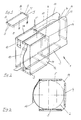
- a box (1) for storing at least one hose (2) or the like, for example a fire-fighting vehicle comprises side wall parts (11, 12) and base parts (3), rear wall parts (4) and cover parts (5).
- the last-mentioned individual parts (3, 4, 5) are of the same design in each hose box construction according to FIG. 1, so that there is a simplified production and nevertheless different compartment variants with differently dimensioned side wall parts (11 or 12) can be designed.
- a hose box with a double hose compartment and a further single hose compartment according to FIG. 2 can be formed with two rear wall parts (11) and a shortened side wall part (12) and seven individual parts according to FIG. 1.
- the individual parts (3, 4, 5) are in particular a rectangular flat plate (6) with an integrated vertical continuous peripheral edge (7), which has fastening holes (8) on the long sides and fastening holes (9) on the end faces.
- the fastening holes (8) serve to receive screws or rivets for the lateral fastening of side wall parts (11 or 12), the fastening holes (9) for fastening the end of belt straps (10), as is shown in particular in FIGS. 2 and 3 .
- FIG. 1 a desired compartment variant of a hose box can be produced by the invention with the aid of simple construction means.
- the flat, stable individual parts of FIG. 1 give the assembled construction a stable hold, and the ends of the belt strap (10) are also securely fastened via the fastening holes (9).
- the belt forces are from the whole Plate part added, not by separate individual pins as in the prior art.
- the webbing fastener can be a buckle fastener or a Velcro fastener.
- the hose box construction mentioned in FIG. 2 is intended for receiving vertically arranged individual hoses. With a corresponding 90 ° rotation of the box, horizontal arrangement of hoses (or wire ropes, etc.) is also possible.
- the individual parts of FIG. 1 are arranged flush with the (upper) edge (13) of the adjacent side wall parts (11, 12).
- the side wall parts (11, 12) can have a bevel (14), which preferably runs at an angle of 45 ° to the horizontal or vertical.
Landscapes
- Public Health (AREA)
- Business, Economics & Management (AREA)
- Emergency Management (AREA)
- Health & Medical Sciences (AREA)
- Fire-Extinguishing By Fire Departments, And Fire-Extinguishing Equipment And Control Thereof (AREA)
- Fittings On The Vehicle Exterior For Carrying Loads, And Devices For Holding Or Mounting Articles (AREA)
- Installation Of Indoor Wiring (AREA)
- Auxiliary Devices For And Details Of Packaging Control (AREA)
- Packaging Of Machine Parts And Wound Products (AREA)
- Thermally Insulated Containers For Foods (AREA)
- Purses, Travelling Bags, Baskets, Or Suitcases (AREA)
- Packaging Of Annular Or Rod-Shaped Articles, Wearing Apparel, Cassettes, Or The Like (AREA)
- Details Of Rigid Or Semi-Rigid Containers (AREA)
Abstract
Description
Die Erfindung betrifft einen Kasten zur Aufbewahrung zumindest eines Schlauchs oder dergl., insbesondere für Feuerlösch-Fahrzeuge gemäß Oberbegriff des Anspruchs 1.The invention relates to a box for storing at least one hose or the like, in particular for fire-fighting vehicles according to the preamble of claim 1.
Aus DE-GM 18 68 927 ist ein Schlauchkasten für Feuerlöschfahrzeuge bekannt, welcher aus einzelnen im wesentlichen gleich ausgebildeten Zwichenwandteilen zwecks Schaffung mehrerer Schlauchfächer zusammengesetzt ist. Jedes Zwischenwandteil besitzt eine geschlossene Seitenwand und einen im wesentlichen senkrecht hierzu verlaufenden geschlossenen Umfangsrand, der an einer Stirnseite, an welcher ein Einzelschlauch aufgenommen werden kann, unterbrochen ist. Die einzelnen Zwischenwandteile werden durch rechtwinklig zu den Wandflächen angeordnete Zapfen, die den Abstand der Zwischenwandteile halten und diese untereinander verbinden, zu der gewünschten Zahl von Schlauchfachabteilen zusammengesetzt. Eine derartige Schlauchkasten-Konstruktion ist sehr aufwendig getroffen und mithin kostenintensiv. Die einzelnen Seitenwandteile müssen Ausfräsungen besitzen, wie auch die Boden- und Rückwandteile in der Kontur gefräst werden müssen. Die Zapfen oder Bolzen, welche die Seitenwandteile miteinander verbinden, müssen sehr stabil ausgebildet sein und bedürfen einer kostenintensiven Fertigung. Sie weisen einen verjüngten Mittelabschnitt auf, um die Enden des Gurtbands befestigen zu können. Da verschiedene Zapfen nicht nur benachbarte Seitenwandteile beabstandet voneinander befestigen, sondern darüber hinaus auch noch die Spannkraft eines Gurtbands in Seitenrichtung aufzunehmen haben, sind diese einer erhöhten Beanspruchung ausgesetzt und führen unter Umständen zu Bruch.From DE-GM 18 68 927 a hose box for fire-fighting vehicles is known, which is composed of individual essentially identical intermediate wall parts for the purpose of creating several hose compartments. Each intermediate wall part has a closed side wall and a closed circumferential edge running essentially perpendicularly thereto, which is interrupted on an end face on which an individual hose can be received. The individual intermediate wall parts are assembled to form the desired number of hose compartment compartments by means of pins arranged at right angles to the wall surfaces, which keep the distance between the intermediate wall parts and connect them to one another. Such a hose box construction is very complex and therefore expensive. The individual side wall parts must have cutouts, as must the base and rear wall parts in the contour. The pins or bolts that connect the side wall parts to each other must be very stable and require costly production. They have a tapered middle section in order to be able to fasten the ends of the webbing. Since different pins not only fasten adjacent side wall parts at a distance from one another, but also have to absorb the tensioning force of a webbing in the lateral direction, they are subjected to increased stress and may lead to breakage.
Aufgabe der Erfindung ist die Schaffung einer Kastenkonstruktion der eingangs genannten Art, die mit Hilfe konstruktiv einfacher Einzelteile gefertigt und zu einer gewünschten Zahl von Schlauchfächern zusammengesetzt werden kann.The object of the invention is to provide a box structure of the type mentioned, which can be manufactured with the aid of structurally simple individual parts and assembled into a desired number of hose compartments.
Gelöst wird die der Erfindung zugrundeliegende Aufgabe durch die im kennzeichnenden Teil des Anspruchs 1 angegebenen Mittel.The object on which the invention is based is achieved by the means specified in the characterizing part of claim 1.
Vorteilhaft weitergebildet ist der Erfindungsgegenstand durch die Merkmale der Ansprüche 2 bis 16.The subject of the invention is advantageously further developed by the features of claims 2 to 16.
Wesen der Erfindung ist mithin identische Ausbildung der Boden-, Rückwand- und Deckelteile des Schlauchkastens. Diese Teile sind vorzugsweise als ebene Platte ausgebildet, wobei die Platte einen vertikalen durchgehenden Umfangsrand besitzt. Umfangsrand und Platte sind zweckmäßigerweise integriert als einstückiges Formteil ausgebildet. Die Platte besitzt im wesentlichen Rechteckform, und es weisen die Längsseiten des Plattenumfangsrands Befestigungslöcher zur seitlichen Befestigung zumindest zweier Schlauchkastenabteile auf. Die Schmalseiten des Plattenumfangsrands besitzen ebenfalls Befestigungslöcher, welche zur stirnseitigen Befestigung eines Gurtbands verwendet werden können. Vorzugsweise besteht jede Einzelplatte aus Kunststoff oder Aluminium. Im zusammengesetzten Zustand der Schlauchkasten-Konstruktion liegen die Längsseiten des Plattenumfangsrands flächig an angrenzenden Seitenwandteilen an, und es verläuft der Rand der Längsseiten des Plattenumfangsrands bündig zum Rand der angrenzenden Seitenwandteile. Ein plattiges Deckelteil ist somit ander Oberseite bündig zwischen zwei seitlichen Seitenwandteilen eingesetzt. Entsprechend weisen Rückwandteile und/oder Bodenteile einen bündigen Abschluß auf. Die erfindungsgemäßen plattigen Teile können mit unterschiedlich dimensionierten Seitenwandteilen zwecks Ausbildung von Einzelschlauchfächern oder Doppelschlauchfächern zusammengesetzt werden. Vergrößerte Seitenwandteile für Doppelschlauchfächer können sich nach hinten erstrecken, um beispielsweise zwei Schläuche in Horizontalrichtung hintereinander anzuordnen; vergrößerte Seitenwandteile können sich aber auch nach oben erstrecken, um zwei Schläuche übereinander in einem Doppelschlauchfach aufzunehmen. Auch können Doppelschlauchfächer mit seitlichen Einzelschlauchfächern kombiniert zusammengesetzt sein. Sämtliche Einzelteile einer Kastenkonstruktion können mittels handelsüblichem Befestigungsmaterial wie Nieten und/oder Schrauben zusammengefügt werden. Die Einzelteile sind einfach ausgebildete Formteile beispielsweise aus Kunststoff oder Aluminium, wobei die Seitenwände auch aus Holz bestehen können. Es ergibt sich eine kostengünstige Montage, und es ist der Einsatz von verschiedenen Materialien (Mischbauweise) gegeben. Besonderer Vorteil der Erfindung ist die integrierte Befestigung von Gurtbändern an den Deckel- oder Bodenteilen selbst, nicht an separaten Zapfen wie nach dem eingangs genannten Stand der Technik. Dadurch werden weniger Einzelteile benötigt. Gleichwohl ist die Befestigung stabil.The essence of the invention is therefore identical design of the bottom, rear wall and lid parts of the hose box. These parts are preferably designed as a flat plate, the plate having a vertical continuous peripheral edge. The peripheral edge and plate are expediently integrated as a one-piece molded part. The plate has a substantially rectangular shape and the longitudinal sides of the peripheral edge of the plate have fastening holes for the lateral fastening of at least two hose box compartments. The narrow sides of the peripheral edge of the plate also have fastening holes which can be used for fastening a webbing at the end. Each individual plate is preferably made of plastic or aluminum. In the assembled state of the hose box construction, the long sides of the plate peripheral edge lie flat against adjacent side wall parts, and the edge of the long sides of the plate peripheral edge runs flush with the edge of the adjacent side wall parts. A flat cover part is thus inserted flush on the upper side between two lateral side wall parts. Correspondingly, rear wall parts and / or base parts have a flush finish. The plate-like parts according to the invention can be assembled with differently dimensioned side wall parts for the purpose of forming single hose compartments or double hose compartments will. Enlarged side wall parts for double hose compartments can extend to the rear, for example to arrange two hoses one behind the other in the horizontal direction; Enlarged side wall parts can also extend upwards to accommodate two hoses one above the other in a double hose compartment. Double hose compartments can also be combined in combination with lateral single hose compartments. All individual parts of a box construction can be assembled using commercially available fastening material such as rivets and / or screws. The individual parts are simply formed molded parts, for example made of plastic or aluminum, and the side walls can also consist of wood. This results in inexpensive assembly and the use of different materials (mixed construction). A particular advantage of the invention is the integrated fastening of belt straps to the cover or base parts themselves, not to separate pins as in the prior art mentioned at the beginning. As a result, fewer individual parts are required. Nevertheless, the attachment is stable.
Die Erfindung wird nachfolgend anhand eines Ausführungsbeispiels unter Bezugnahme auf die beigefügte Zeichnung näher erläutert; es zeigen:
- Fig. 1
- ein Deckel-, Boden- und/der Rückwandteil eines erfindungsgemäßen Schlauchkastens,
- Fig. 2
- in perspektivischer Ansicht einen Schlauchkasten unter mehrfacher Verwendung des Einzelteils nach Fig. 1, wobei der Schlauchkasten ein Doppelschlauch-und ein Einzelschlauchabteil besitzt, und
- Fig. 3
- das Einzelschlauchabteil in schematischer Seitenansicht.
- Fig. 1
- a lid, bottom and / or the rear wall part of a hose box according to the invention,
- Fig. 2
- a perspective view of a hose box using the individual part according to FIG. 1, the hose box has a double hose and a single hose compartment, and
- Fig. 3
- the single tube compartment in a schematic side view.
Gemäß Zeichnung umfaßt ein Kasten (1) zur Aufbewahrung zumindest eines Schlauchs (2) oder dergl. beispielsweise eines Feuerlösch-Fahrzeugs Seitenwandteile (11,12) und Bodenteile (3), Rückwandteile (4) und Deckelteile (5). Letztgenannte Einzelteile (3,4,5) sind bei jeder Schlauchkasten-Konstruktion gemäß Fig. 1 gleich ausgebildet, so daß sich eine vereinfachte Fertigung ergibt und gleichwohl unterschiedliche Fachvarianten mit unterschiedlich dimensionierten Seitenwandteilen (11 bzw. 12) konzipiert werden können. Beispielsweise können mit zwei nach hinten verlängerten Seitenwandteilen (11) und einem verkürzten Seitenwandteil (12) und sieben Einzelteilen nach Fig. 1 ein Schlauchkasten mit einem Doppelschlauchabteil und einem weiteren Einzelschlauchabteil gemäß Fig. 2 ausgebildet werden. Es sind also zwei gleich ausgebildete Deckelteile (5), zwei entsprechend gleich ausgebildete Rückwandteile (4) und drei ebenfalls gleich ausgebildete Bodenteile (3) vorgesehen.According to the drawing, a box (1) for storing at least one hose (2) or the like, for example a fire-fighting vehicle, comprises side wall parts (11, 12) and base parts (3), rear wall parts (4) and cover parts (5). The last-mentioned individual parts (3, 4, 5) are of the same design in each hose box construction according to FIG. 1, so that there is a simplified production and nevertheless different compartment variants with differently dimensioned side wall parts (11 or 12) can be designed. For example, a hose box with a double hose compartment and a further single hose compartment according to FIG. 2 can be formed with two rear wall parts (11) and a shortened side wall part (12) and seven individual parts according to FIG. 1. There are therefore two identically designed cover parts (5), two correspondingly designed rear wall parts (4) and three likewise identical bottom parts (3).
Die Einzelteile (3,4,5) sind im besonderen eine rechteckige ebene Platte (6) mit integriert ausgebildetem vertikalen durchgehenden Umfangsrand (7), der an den Längsseiten Befestigungslöcher (8) und an den Stirnseiten Befestigungslöcher (9) aufweist. Die Befestigungslöcher (8) dienen zur Aufnahme von Schrauben oder Nieten zur seitlichen Befestigung von Seitenwandteilen (11 bzw. 12), die Befestigungslöcher (9) zur stirnseitigen Befestigung von Gurtbändern (1O), wie dies insbesondere in den Fig. 2 und 3 dargestellt ist.The individual parts (3, 4, 5) are in particular a rectangular flat plate (6) with an integrated vertical continuous peripheral edge (7), which has fastening holes (8) on the long sides and fastening holes (9) on the end faces. The fastening holes (8) serve to receive screws or rivets for the lateral fastening of side wall parts (11 or 12), the fastening holes (9) for fastening the end of belt straps (10), as is shown in particular in FIGS. 2 and 3 .
Ersichtlich kann durch die Erfindung mit Hilfe einfacher Konstruktionsmittel eine gewünschte Fachvariante eines Schlauchkastens hergestellt werden. Die flächigen stabilen Einzelteile der Fig. 1 verleihen der zusammengesetzten Konstruktion einen stabilen Halt, und es sind auch über die Befestigungslöcher (9) die Enden des Gurtbands (1O) stabil befestigt. Die Gurtkräfte werden vom gesamten Plattenteil aufgenommen, nicht von gesonderten Einzelzapfen wie nach dem Stand der Technik.Obviously, a desired compartment variant of a hose box can be produced by the invention with the aid of simple construction means. The flat, stable individual parts of FIG. 1 give the assembled construction a stable hold, and the ends of the belt strap (10) are also securely fastened via the fastening holes (9). The belt forces are from the whole Plate part added, not by separate individual pins as in the prior art.
Der Gurtbandverschluß kann ein Schnallenverschluß oder ein Klettbandverschluß sein.The webbing fastener can be a buckle fastener or a Velcro fastener.
Die in Fig. 2 genannte Schlauchkasten-Konstruktion ist zur Aufnahme von vertikal angeordneten Einzelschläuchen vorgesehen. Bei entsprechender 9O°-Drehung des Kastens kommt auch Horizontalanordnung von Schläuchen (oder Drahtseilen, etc.) in Frage.The hose box construction mentioned in FIG. 2 is intended for receiving vertically arranged individual hoses. With a corresponding 90 ° rotation of the box, horizontal arrangement of hoses (or wire ropes, etc.) is also possible.
Im zusammengesetzten Zustand der Anordnung sind die Einzelteile der Fig. 1 bündig zum (oberen) Rand (13) der angrenzenden Seitenwandteile (11,12) angeordnet. Im Bereich von Rückwandteilen (4) können die Seitenwandteile (11,12) eine Abschrägung (14) besitzen, die vorzugsweise unter einem Winkel von 45° zur Horizontalen bzw. Vertikalen verläuft.In the assembled state of the arrangement, the individual parts of FIG. 1 are arranged flush with the (upper) edge (13) of the adjacent side wall parts (11, 12). In the area of rear wall parts (4), the side wall parts (11, 12) can have a bevel (14), which preferably runs at an angle of 45 ° to the horizontal or vertical.
Claims (16)
- A box (1) for the storage of at least one hose (2), wire cable or the like, especially for fire-fighting vehicles, with floor, side wall, rear wall and ceiling parts and front belt (10) for the purpose of securing the hose or the like stored in the box, characterised in that the floor, rear wall and ceiling parts (3, 4 and 5 respectively) are identical.
- A box according to Claim 1, characterised in that the floor, rear wall and ceiling parts (3, 4 and 5) are made as flat plates (6) with vertical continuous peripheral edge (7).
- A box according to Claim 2, characterised in that the peripheral edge (7) is made in one piece with the plate (6).
- A box according to Claim 2 or 3, characterised in that the plate (6) possesses a substantially rectangular form.
- A box according to any one of Claims 2 to 4, characterised in that the longitudinal side of the plate peripheral edge (7) comprises fastening holes (8) for the lateral fastening of at least two hose box sections.
- A box according to Claim 4 or 5, characterised in that the short side of the plate peripheral edge (7) comprises fastening holes (9) for the end fastening of the belt (10).
- A box according to any one of Claims 1 to 6, characterised in that the plate (6) comprises synthetic plastics material or aluminium.
- A box according to any one of Claims 1 to 7, characterised in that the longitudinal sides of the plate peripheral edge (7) rest flatly on the adjoining side wall parts (11, 12).
- A box according to Claim 8, characterised in that the edge of each of the longitudinal sides of the plate peripheral edge (7) extends flush with the upper edge (13) of the adjoining side wall parts (11, 12).
- A box according to any one of Claims 1 to 9, characterised in that for the storage of at least two hoses or the like or one single longer hose, enlarged side wall parts (11) are provided.
- A box according to Claim 10, characterised in that the enlarged side wall parts (11) extend to the rear, and at least two plate-type floor parts (3) are provided (Figure 2).
- A box according to Claim 10, characterised in that the enlarged side wall parts (11) extend upwards, while at least two plate-type rear wall parts (4) are provided.
- A box according to Claim 11 or Claim 12, characterised in that a double hose compartment is formed in combination with a lateral single hose compartment (Figure 2).
- A box according to any one of Claims 1 to 13, characterised in that the side wall parts (11, 12) possess at least one chamfer (14) in the region of the rear wall part (4).
- A box according to any one of Claims 1 to 14, characterised in that the side wall parts (11, 12) are formed from wood, synthetic plastics material or aluminium.
- A box according to any one of Claims 1 to 14, characterised in that the side wall parts (11, 12) and the plates (6) are formed from different materials.
Priority Applications (1)
| Application Number | Priority Date | Filing Date | Title |
|---|---|---|---|
| AT87106918T ATE68982T1 (en) | 1986-05-28 | 1987-05-13 | HOSE BOX. |
Applications Claiming Priority (2)
| Application Number | Priority Date | Filing Date | Title |
|---|---|---|---|
| DE3618014 | 1986-05-28 | ||
| DE19863618014 DE3618014A1 (en) | 1986-05-28 | 1986-05-28 | HOSE BOX |
Publications (3)
| Publication Number | Publication Date |
|---|---|
| EP0247435A2 EP0247435A2 (en) | 1987-12-02 |
| EP0247435A3 EP0247435A3 (en) | 1989-03-22 |
| EP0247435B1 true EP0247435B1 (en) | 1991-10-30 |
Family
ID=6301833
Family Applications (1)
| Application Number | Title | Priority Date | Filing Date |
|---|---|---|---|
| EP87106918A Expired - Lifetime EP0247435B1 (en) | 1986-05-28 | 1987-05-13 | Hose box |
Country Status (3)
| Country | Link |
|---|---|
| EP (1) | EP0247435B1 (en) |
| AT (1) | ATE68982T1 (en) |
| DE (2) | DE3618014A1 (en) |
Families Citing this family (4)
| Publication number | Priority date | Publication date | Assignee | Title |
|---|---|---|---|---|
| DE19820856C2 (en) * | 1998-05-09 | 2000-02-24 | Reg Reifen Entsorgungsgesellsc | Storage and transport containers for tires or vehicle wheels |
| ES2608343B1 (en) * | 2015-09-04 | 2018-05-07 | Lidia MENA SALADO | Equipment for installations and control of flat hoses |
| CN106621127B (en) * | 2017-02-17 | 2022-04-12 | 中国民航科学技术研究院 | Fire-resistant explosion-proof emergency treatment box |
| ES1223719Y (en) * | 2018-11-29 | 2019-04-17 | Ojeda Juan Jesus Romero | PORTABLE REEL FOR FIRE EXTINGUISHING HOSES |
Family Cites Families (2)
| Publication number | Priority date | Publication date | Assignee | Title |
|---|---|---|---|---|
| DE1868927U (en) * | 1962-12-04 | 1963-03-14 | Kloeckner Humboldt Deutz Ag | HOSE COMPARTMENT INSERT FOR FIRE-EXTINGUISHING VEHICLES. |
| GB1406904A (en) * | 1972-03-14 | 1975-09-17 | Kanebo Ltd | Portable fire-hose |
-
1986
- 1986-05-28 DE DE19863618014 patent/DE3618014A1/en not_active Withdrawn
-
1987
- 1987-05-13 EP EP87106918A patent/EP0247435B1/en not_active Expired - Lifetime
- 1987-05-13 AT AT87106918T patent/ATE68982T1/en not_active IP Right Cessation
- 1987-05-13 DE DE8787106918T patent/DE3774175D1/en not_active Expired - Lifetime
Also Published As
| Publication number | Publication date |
|---|---|
| EP0247435A2 (en) | 1987-12-02 |
| DE3774175D1 (en) | 1991-12-05 |
| ATE68982T1 (en) | 1991-11-15 |
| EP0247435A3 (en) | 1989-03-22 |
| DE3618014A1 (en) | 1987-12-03 |
Similar Documents
| Publication | Publication Date | Title |
|---|---|---|
| DE19726500B4 (en) | Separating device for a cableway | |
| DE602004004731T2 (en) | Connector for a rail slot | |
| DE2713804C2 (en) | Vehicle luggage rack | |
| DE4004829C2 (en) | ||
| EP1344712A2 (en) | Composite part, especially as hang-on part or body panel for a car | |
| DE2947403A1 (en) | VEHICLE LUGGAGE RACK | |
| DE19941714C2 (en) | Holding device in a motor vehicle | |
| EP0247435B1 (en) | Hose box | |
| DE4017160C2 (en) | Side protection | |
| DE68903348T2 (en) | ASSEMBLY OF THE TYPE SEMI-TRAILER TYPE. | |
| DE9312947U1 (en) | Device for fixing conveyed goods in vehicles | |
| EP1029810A1 (en) | Flexible partition arrangement | |
| WO2005118382A1 (en) | Motorcycle comprising a holding device for a lateral case | |
| DE3424690C2 (en) | Self-supporting bus body | |
| DE3622018A1 (en) | Device for securing loads in motor vehicles | |
| DE9413049U1 (en) | Device for fastening a cover strip for grooves in motor vehicle bodies | |
| DE102021103507B4 (en) | Railing for a motor vehicle | |
| DE10061349C2 (en) | Device for strain relief of dynamically stressed cables in an energy chain | |
| DE2418313C2 (en) | Frame construction that surrounds a load floor, for example of a truck | |
| DE19617454A1 (en) | Wire mesh safety/dividing wall for motor vehicle interior | |
| DE7701184U1 (en) | Cabin for a motor vehicle | |
| DE10259388A1 (en) | Device for securing of loads on load carrying surface has insert profile installed in channel space in rail profile and fits under engagement recesses for insertion of retaining components | |
| EP0168348A1 (en) | Mounting of a vehicle body on a chassis | |
| DE4300714A1 (en) | Inner ceiling fastening in railway coach | |
| DE3303774A1 (en) | LOADING BOARD |
Legal Events
| Date | Code | Title | Description |
|---|---|---|---|
| PUAI | Public reference made under article 153(3) epc to a published international application that has entered the european phase |
Free format text: ORIGINAL CODE: 0009012 |
|
| AK | Designated contracting states |
Kind code of ref document: A2 Designated state(s): AT CH DE FR GB LI |
|
| PUAL | Search report despatched |
Free format text: ORIGINAL CODE: 0009013 |
|
| AK | Designated contracting states |
Kind code of ref document: A3 Designated state(s): AT CH DE FR GB LI |
|
| 17P | Request for examination filed |
Effective date: 19890826 |
|
| 17Q | First examination report despatched |
Effective date: 19901213 |
|
| GRAA | (expected) grant |
Free format text: ORIGINAL CODE: 0009210 |
|
| AK | Designated contracting states |
Kind code of ref document: B1 Designated state(s): AT CH DE FR GB LI |
|
| REF | Corresponds to: |
Ref document number: 68982 Country of ref document: AT Date of ref document: 19911115 Kind code of ref document: T |
|
| ET | Fr: translation filed | ||
| REF | Corresponds to: |
Ref document number: 3774175 Country of ref document: DE Date of ref document: 19911205 |
|
| GBT | Gb: translation of ep patent filed (gb section 77(6)(a)/1977) | ||
| PLBE | No opposition filed within time limit |
Free format text: ORIGINAL CODE: 0009261 |
|
| STAA | Information on the status of an ep patent application or granted ep patent |
Free format text: STATUS: NO OPPOSITION FILED WITHIN TIME LIMIT |
|
| 26N | No opposition filed | ||
| REG | Reference to a national code |
Ref country code: GB Ref legal event code: IF02 |
|
| PGFP | Annual fee paid to national office [announced via postgrant information from national office to epo] |
Ref country code: GB Payment date: 20030509 Year of fee payment: 17 |
|
| PGFP | Annual fee paid to national office [announced via postgrant information from national office to epo] |
Ref country code: AT Payment date: 20030516 Year of fee payment: 17 |
|
| PGFP | Annual fee paid to national office [announced via postgrant information from national office to epo] |
Ref country code: DE Payment date: 20030522 Year of fee payment: 17 |
|
| PGFP | Annual fee paid to national office [announced via postgrant information from national office to epo] |
Ref country code: FR Payment date: 20030528 Year of fee payment: 17 |
|
| PGFP | Annual fee paid to national office [announced via postgrant information from national office to epo] |
Ref country code: CH Payment date: 20030822 Year of fee payment: 17 |
|
| PG25 | Lapsed in a contracting state [announced via postgrant information from national office to epo] |
Ref country code: GB Free format text: LAPSE BECAUSE OF NON-PAYMENT OF DUE FEES Effective date: 20040513 Ref country code: AT Free format text: LAPSE BECAUSE OF NON-PAYMENT OF DUE FEES Effective date: 20040513 |
|
| PG25 | Lapsed in a contracting state [announced via postgrant information from national office to epo] |
Ref country code: LI Free format text: LAPSE BECAUSE OF NON-PAYMENT OF DUE FEES Effective date: 20040531 Ref country code: CH Free format text: LAPSE BECAUSE OF NON-PAYMENT OF DUE FEES Effective date: 20040531 |
|
| PG25 | Lapsed in a contracting state [announced via postgrant information from national office to epo] |
Ref country code: DE Free format text: LAPSE BECAUSE OF NON-PAYMENT OF DUE FEES Effective date: 20041201 |
|
| GBPC | Gb: european patent ceased through non-payment of renewal fee |
Effective date: 20040513 |
|
| REG | Reference to a national code |
Ref country code: CH Ref legal event code: PL |
|
| PG25 | Lapsed in a contracting state [announced via postgrant information from national office to epo] |
Ref country code: FR Free format text: LAPSE BECAUSE OF NON-PAYMENT OF DUE FEES Effective date: 20050131 |
|
| REG | Reference to a national code |
Ref country code: FR Ref legal event code: ST |