EP0247130B1 - Strand for stressed concrete structure and process for its production - Google Patents
Strand for stressed concrete structure and process for its production Download PDFInfo
- Publication number
- EP0247130B1 EP0247130B1 EP86906911A EP86906911A EP0247130B1 EP 0247130 B1 EP0247130 B1 EP 0247130B1 EP 86906911 A EP86906911 A EP 86906911A EP 86906911 A EP86906911 A EP 86906911A EP 0247130 B1 EP0247130 B1 EP 0247130B1
- Authority
- EP
- European Patent Office
- Prior art keywords
- strand
- wires
- section
- cross
- wire
- Prior art date
- Legal status (The legal status is an assumption and is not a legal conclusion. Google has not performed a legal analysis and makes no representation as to the accuracy of the status listed.)
- Expired - Lifetime
Links
Images
Classifications
-
- D—TEXTILES; PAPER
- D07—ROPES; CABLES OTHER THAN ELECTRIC
- D07B—ROPES OR CABLES IN GENERAL
- D07B1/00—Constructional features of ropes or cables
- D07B1/06—Ropes or cables built-up from metal wires, e.g. of section wires around a hemp core
- D07B1/08—Ropes or cables built-up from metal wires, e.g. of section wires around a hemp core the layers of which are formed of profiled interlocking wires, i.e. the strands forming concentric layers
-
- E—FIXED CONSTRUCTIONS
- E04—BUILDING
- E04C—STRUCTURAL ELEMENTS; BUILDING MATERIALS
- E04C5/00—Reinforcing elements, e.g. for concrete; Auxiliary elements therefor
- E04C5/08—Members specially adapted to be used in prestressed constructions
Definitions
- the invention relates to a stressed concrete structure strand comprising at least three wires twisted together and to a method for producing a stressed concrete structure strand wherein a first cross-section of individual wires is formed and then at least three wires are twisted to form a strand.
- strands are used for pre-stressed, or after-stressed (reinforced) concrete structures to take up the stretching force. These are formed generally with three to seven pieces of 2 to 5 mm thick cold drawn individual steel wires, so-called “elementary filaments” to cable-type strand with the use of twisting (stranding) machine. These strands transmit the stretching force to the concrete structure through adhesion, or anchorage between the strand and the concrete.
- Such strands and cables are already known from the British patent specification No. 1 194 758 and GFR patent specification No. 1 659 265, where evenly distributed (periodic) profiling of small depth is produced by rolling after cold drawing on the surface of the covering wires of the strand, just as in case of the simple concrete reinforcing rods.
- the adhesive capacity of the strand in the concrete is improved by the periodic profiling formed with such indentation, i.e. "the anchoring length" will be shorter, however the increased risk of cracking or breakage must be reckoned with in the elementary filaments at the corners of the indentations upon the bending and torsional stresses arising during loading of the strand.
- the arrangement of the periodic surface profiles within the strand is incidental, in other words, the "functional" cross section surfaces of the sections perpendicular to the longitudinal axis of the strand are different from each other, consequently the stress conditions arising during loading are also different. This implies that the possibly smallest cross section is to be reckoned with for strength calculation of the strand, which however is unfavourable in respect of the steel utilization.
- DE-A-2 416 633 discloses reinforcement strands made from rods or strips for normal unstressed concrete structures. However, said strands cannot be stressed because they do not go through the whole concrete element.
- the length to diameter ratio is preferably between 70 and 160. With a diameter of 0,35 mm, the length will be between 2,50 cm and 5,6 cm. Even if the strands were long enough for use unstressed concrete the suggested tensile strength range of 830 N/mm2 to 1370 N/mm2 is inadequate for stressed concrete.
- the round wires of said document are fixed together by a binder and are arranged uniplanar.
- the object is solved in that all the wires forming the strand have the same non-circular cross-section along their whole length.
- the object is also solved by a method for producing a stressed concrete structure strand, wherein a first cross-section of individual wires is formed and then at least three wires are twisted to form a strand by forming all the individual wires with the same cross-section as a uniform non-circular one along their length by cold drawing the wire through a drawplate.
- Such strand which has a twist formed with at least three wires provided with surface profiling.
- the cross section profile of the wires continuously passing through in longitudinal direction may suitably be a polygonal profile, preferably a rounded regular hexagon. This enables a very simple production.
- cross section profile of the wires continuously passing through in longitudinal direction is formed as such circular or polygonal cross section, which is provided with longitudinal groove-like recesses and/or rib-like extensions evenly distributed along the circumference.
- the starting point was such conventional method where first the surface profiling of the wires is formed with cold deformation, then at least three wires are formed to strand with simultaneous twisting.
- the essence of the process according to the invention is that the surface profiling of the wires is formed by drawing through drawplate of non-circular, preferably rounded hexagonal cross section.
- the wires it is advisable to form the wires by turning around their longitudinal axis during or after formation of the profile, but before twisting. It is expedient if the turning direction of the wires coincides with the subsequent twisting direction of the strand. Furthermore, it is preferable if the pitch of the twisting is selected to the multiple, suitably at least to tenfold of the pitch of wire-turning.
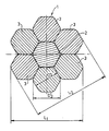
- the invention is described in detail with the aid of drawing, showing the cross section of the strand according to the invention given by way of example, and drawn to enlarged scale.
- the strand denoted with reference number 1 in this case consists of a central wire 2, (i.e. "supporting core wire") and tangentially surrounding six covering wires 3.
- the covering wires 3 in contact with the concrete in built-in state and the cover wire 2 have non-cirucular cross section profile continuously passing through in longitudinal direction for the purpose of increased adhesion to the concrete, and establishing indentical stress conditions in all strand cross sections.
- the covering wires 3 are of regular hexagonal cross section, rounded on the corners.
- the diameter of the circle drawable into the hexagon in case of the cover wire is marked with D3
- diameter of the circle drawable around the hexagon with D ' 3
- the embracing face-distance of strand 1 with L1 while its distance between centres is marked with L2.
- the diameter of the central wire 2 is greater by 3-4 % than the diameter D ' 3 of the covering wires 3 for better seating of the covering wires 3.
- the diameter of central wire 2 was selected to 4.26 mm, and the diameter D ' 3 of the covering wires 3 to 4.11 mm.
- the covering wires 3 are shown in ideal state in the drawing, where the hexangonal faces of the adjacent wires 3 bear up on each other. In the reality this rarely occurs.
- Production of the strand 1 according to the invention is the following:
- the production technology of the central wire 2 and covering wires 3 is essentially conventional.
- the covering wire 3 is turned around its longitudinal axis (naturally this can be dispensed with in given case) while passing through the drawplate.
- the pitch of wire-turning is determined by the pitch of the drawplate.
- the drawplate was embedded as to be capable to turn around the advanced wire.
- the twist i.e. the strand 1 is formed on a conventional twisting machine with the central wire 2 and six covering wires 3.
- the turning direction of the covering wires 3 was selected to be identical with the direction of twisting, furthermore the pitch of twisting was selected to about tenfold of the turning pitch.
- any cross section of the strand is identical, consequently the arising stress conditions too are identical.
- the surface area increased according to the periodic profiling results in improved anchoring capacity of the strand 1, consequently the load bearing capacity of the strand 1 and its safety factor are also increased.
- the use of steel, i.e. material is less for the strand provided with covering wires of helical hexagon cross section according to the invention.
- the central wire 2 is omitted.
- the central wire may be identical with the covering wires.
- any other non-circular profile can also be used with similar result, e.g. as polygonal cross sections, thus regular pentagon, octogon, etc.
- such circular or polygonal profile too may come into question at least for the covering wires, which is provided with groovelike recesses passing through in longitudinal direction, and/or rib-like, or web-like extensions passing through in longitudinal direction.
- the cold deformation of the three latter ones may be accomplished in any other way, e.g. by rolling.
Landscapes
- Engineering & Computer Science (AREA)
- Architecture (AREA)
- Civil Engineering (AREA)
- Structural Engineering (AREA)
- Reinforcement Elements For Buildings (AREA)
- Ropes Or Cables (AREA)
- On-Site Construction Work That Accompanies The Preparation And Application Of Concrete (AREA)
- Diaphragms For Electromechanical Transducers (AREA)
- Polishing Bodies And Polishing Tools (AREA)
- Sewage (AREA)
- Curing Cements, Concrete, And Artificial Stone (AREA)
- Heat Treatment Of Steel (AREA)
- Preparation Of Clay, And Manufacture Of Mixtures Containing Clay Or Cement (AREA)
- Disintegrating Or Milling (AREA)
Abstract
Description
- The invention relates to a stressed concrete structure strand comprising at least three wires twisted together and to a method for producing a stressed concrete structure strand wherein a first cross-section of individual wires is formed and then at least three wires are twisted to form a strand.
- As known, different strands are used for pre-stressed, or after-stressed (reinforced) concrete structures to take up the stretching force. These are formed generally with three to seven pieces of 2 to 5 mm thick cold drawn individual steel wires, so-called "elementary filaments" to cable-type strand with the use of twisting (stranding) machine. These strands transmit the stretching force to the concrete structure through adhesion, or anchorage between the strand and the concrete.
- The experts have been trying to find a solution for a long time, whereby adhesion or holding power of the strands to the concrete could be improved, since this way the stretching force could be increased, which would be particularly desirable especially in case of high load bearing stressed concrete structures, or long spans.
- Such strands and cables are already known from the British patent specification No. 1 194 758 and GFR patent specification No. 1 659 265, where evenly distributed (periodic) profiling of small depth is produced by rolling after cold drawing on the surface of the covering wires of the strand, just as in case of the simple concrete reinforcing rods.
- Although the adhesive capacity of the strand in the concrete is improved by the periodic profiling formed with such indentation, i.e. "the anchoring length" will be shorter, however the increased risk of cracking or breakage must be reckoned with in the elementary filaments at the corners of the indentations upon the bending and torsional stresses arising during loading of the strand. Furthermore, the arrangement of the periodic surface profiles within the strand is incidental, in other words, the "functional" cross section surfaces of the sections perpendicular to the longitudinal axis of the strand are different from each other, consequently the stress conditions arising during loading are also different. This implies that the possibly smallest cross section is to be reckoned with for strength calculation of the strand, which however is unfavourable in respect of the steel utilization.
- Furthermore such process for strand production is recommended by the British patent specification No. 1 336 200, where the strand twisted from round wires is tightened by deformation with radial external pressure. In the course of this, mainly the covering wires pass through free deformation, while their concentric cross section will be deformed to irregular shape. The purpose of tightening is to obtain the possibly smallest strand cross section mainly for the after-stressed structures. This tightening however inevitably entails reduction of the outer surface of the strand in contact with the concrete, which in view of the foregoing is undesirable in respect of the adhesion.
- DE-A-2 416 633 discloses reinforcement strands made from rods or strips for normal unstressed concrete structures. However, said strands cannot be stressed because they do not go through the whole concrete element. The length to diameter ratio is preferably between 70 and 160. With a diameter of 0,35 mm, the length will be between 2,50 cm and 5,6 cm. Even if the strands were long enough for use unstressed concrete the suggested tensile strength range of 830 N/mm² to 1370 N/mm² is inadequate for stressed concrete. The round wires of said document are fixed together by a binder and are arranged uniplanar.
- It is therefore an object of the invention to eliminate the above short comings, i.e. when realizing and manufacturing such strand for stressed reinforced concrete structures, whereby the adhesion to concrete can be improved and at the same time identical stress conditions can be assured in all strand cross sections.
- The object is solved in that all the wires forming the strand have the same non-circular cross-section along their whole length.
- The object is also solved by a method for producing a stressed concrete structure strand, wherein a first cross-section of individual wires is formed and then at least three wires are twisted to form a strand by forming all the individual wires with the same cross-section as a uniform non-circular one along their length by cold drawing the wire through a drawplate.
- Further embodiments are included in the subclaims 2 to 6 and 8 to 10.
- Initially such strand was used, which has a twist formed with at least three wires provided with surface profiling. This was further developed according to the invention in that the surface profiling of the wires is formed as non-circular cross section-profile continuously passing through the wire in longitudinal direction.
- The cross section profile of the wires continuously passing through in longitudinal direction may suitably be a polygonal profile, preferably a rounded regular hexagon. This enables a very simple production.
- According to a further characteristic feature of the invention such construction is also conceivable, where the cross section profile of the wires continuously passing through in longitudinal direction is formed as such circular or polygonal cross section, which is provided with longitudinal groove-like recesses and/or rib-like extensions evenly distributed along the circumference.
- In the course of the development of the method for the production of the strand according to the invention the starting point was such conventional method where first the surface profiling of the wires is formed with cold deformation, then at least three wires are formed to strand with simultaneous twisting.
- The essence of the process according to the invention is that the surface profiling of the wires is formed by drawing through drawplate of non-circular, preferably rounded hexagonal cross section.
- It is advisable to form the wires by turning around their longitudinal axis during or after formation of the profile, but before twisting. It is expedient if the turning direction of the wires coincides with the subsequent twisting direction of the strand. Furthermore, it is preferable if the pitch of the twisting is selected to the multiple, suitably at least to tenfold of the pitch of wire-turning.
- The invention is described in detail with the aid of drawing, showing the cross section of the strand according to the invention given by way of example, and drawn to enlarged scale. As seen, the strand denoted with reference number 1, in this case consists of a central wire 2, (i.e. "supporting core wire") and tangentially surrounding six covering
wires 3. - According to the invention the covering
wires 3 in contact with the concrete in built-in state and the cover wire 2 have non-cirucular cross section profile continuously passing through in longitudinal direction for the purpose of increased adhesion to the concrete, and establishing indentical stress conditions in all strand cross sections. In the presented case thecovering wires 3 are of regular hexagonal cross section, rounded on the corners. In the drawing the diameter of the circle drawable into the hexagon in case of the cover wire is marked with D₃, diameter of the circle drawable around the hexagon with D
- It is advisable to dimension the diameter of the central wire 2 greater by 3-4 % than the diameter D

covering wires 3 for better seating of thecovering wires 3. In case of the 1/2" strand - given by way of examples - the diameter of central wire 2 was selected to 4.26 mm, and the diameter D
covering wires 3 to 4.11 mm. - It is noted that the
covering wires 3 are shown in ideal state in the drawing, where the hexangonal faces of theadjacent wires 3 bear up on each other. In the reality this rarely occurs. - Production of the strand 1 according to the invention is the following:
The production technology of the central wire 2 and coveringwires 3 is essentially conventional. In the production of the coveringwires 3 according to the invention only the last step of the cold deformation is different, where special drawplate of hexagonal opening cross section was used to obtain the required cross section. - In the present case the
covering wire 3 is turned around its longitudinal axis (naturally this can be dispensed with in given case) while passing through the drawplate. The pitch of wire-turning is determined by the pitch of the drawplate. During the experiments the drawplate was embedded as to be capable to turn around the advanced wire. - After finishing the production of the
covering wires 3, the twist, i.e. the strand 1 is formed on a conventional twisting machine with the central wire 2 and sixcovering wires 3. In the course of the experiments the turning direction of thecovering wires 3 was selected to be identical with the direction of twisting, furthermore the pitch of twisting was selected to about tenfold of the turning pitch. As a result of this, after the twisting favourable contact between thewires 2 and 3, and after building in the strand 1 the possibly most favourable anchorage were accomplished with the illustrated helical hexagon profile. - Naturally the strength properties of the strand can be improved by the conventional heat treatments widely used in the practice (e.g. tempering, stabilization), which however are obvious for the expert in the art, thus their description is unnecessary.
- The experiences of the experiments demonstrated that the illustrated strand 1 according to the invention can be produced simply and productively at relatively low additional cost, with traditional equipment. Owing to the hexagonal cross section of the covering wires continuous in longitudinal direction, any cross section of the strand is identical, consequently the arising stress conditions too are identical. The surface area increased according to the periodic profiling results in improved anchoring capacity of the strand 1, consequently the load bearing capacity of the strand 1 and its safety factor are also increased. Or assuming for instance identical load bearing, compared to traditional strand of periodic profiling, the use of steel, i.e. material is less for the strand provided with covering wires of helical hexagon cross section according to the invention.
- Naturally for example in the case of a three-wire strand the central wire 2 is omitted. Moreover, in case of multi-wire strands the central wire may be identical with the covering wires. Furthermore, according to the invention in place of the above described hexagon profile any other non-circular profile can also be used with similar result, e.g. as polygonal cross sections, thus regular pentagon, octogon, etc. In addition, such circular or polygonal profile too may come into question at least for the covering wires, which is provided with groovelike recesses passing through in longitudinal direction, and/or rib-like, or web-like extensions passing through in longitudinal direction. The cold deformation of the three latter ones may be accomplished in any other way, e.g. by rolling.
Claims (10)
- Stressed concrete structure strand comprising at least three wires (2, 3) twisted together, characterized in that all the wires (2, 3) forming the strand have the same, uniform non-circular cross section along their whole length.
- Strand according to claim 1, characterized in that the uniform non-circular cross-section is polygonal.
- Strand according to claim 2, characterized in that the polygonal cross-section has rounded corners.
- Strand of claim 1, characterized in that the uniform non-circular cross-section is a regular hexagon and the wires (3) are twisted along their longitudinal axes.
- Strand of claim 1, 2, 3 or 4, characterized in that at least some of the wires (3) are provided with longitudinal groove-like recesses continuously along their whole length.
- Strand of claim 1, 2, 3 or 4, characterized in that at least some of the wires (3) are provided with longitudinal web-like extensions continuously along their whole length.
- Method for producing a stressed concrete sructure strand wherein a first cross section of individual wires is formed and then at least three wires are twisted to form a strand, characterized by forming all the individual wires with the same cross section as a uniform non-circular one along their whole length by cold drawing the wire through a draw plate.
- Method according to claim 7, characterized in that prior to the twisting step the individual wires (3) are deformed by being turned about their respective individual longitudinal axes.
- Method according to claim 8, characterized in that the turning direction for the individual wires (3) coincides with the subsequent twisting direction for the whole strand (1).
- Method according to claim 9, characterized in that the pitch of the strand's twisting is selected to be a multiple, preferably tenfold of the pitch of the wire-turning for the individual wires.
Priority Applications (1)
| Application Number | Priority Date | Filing Date | Title |
|---|---|---|---|
| AT86906911T ATE72282T1 (en) | 1985-11-26 | 1986-11-18 | PRE-PRESSURE STEEL FOR PRE-PRESSED CONCRETE AND METHOD FOR ITS MANUFACTURE. |
Applications Claiming Priority (2)
| Application Number | Priority Date | Filing Date | Title |
|---|---|---|---|
| HU451185 | 1985-11-26 | ||
| HU854511A HU204312B (en) | 1985-11-26 | 1985-11-26 | Stretching staple for stressed concrete structures |
Publications (2)
| Publication Number | Publication Date |
|---|---|
| EP0247130A1 EP0247130A1 (en) | 1987-12-02 |
| EP0247130B1 true EP0247130B1 (en) | 1992-01-29 |
Family
ID=10968173
Family Applications (1)
| Application Number | Title | Priority Date | Filing Date |
|---|---|---|---|
| EP86906911A Expired - Lifetime EP0247130B1 (en) | 1985-11-26 | 1986-11-18 | Strand for stressed concrete structure and process for its production |
Country Status (9)
| Country | Link |
|---|---|
| EP (1) | EP0247130B1 (en) |
| AT (1) | ATE72282T1 (en) |
| CS (1) | CS274284B2 (en) |
| DD (1) | DD259228A1 (en) |
| DE (1) | DE3683769D1 (en) |
| FI (1) | FI873196A (en) |
| HU (1) | HU204312B (en) |
| NO (1) | NO873118L (en) |
| WO (1) | WO1987003322A1 (en) |
Families Citing this family (1)
| Publication number | Priority date | Publication date | Assignee | Title |
|---|---|---|---|---|
| BE1015295A3 (en) * | 2003-01-08 | 2005-01-11 | Fontainunion S A | Building element for concrete. |
Family Cites Families (6)
| Publication number | Priority date | Publication date | Assignee | Title |
|---|---|---|---|---|
| NL193905A (en) * | 1953-11-07 | 1900-01-01 | ||
| IL32159A (en) * | 1968-10-30 | 1973-06-29 | Ivanier I | Cold drawn ribbed metal wire products;apparatus and process for the production thereof |
| US3735625A (en) * | 1970-07-28 | 1973-05-29 | Naniwa Seitel Co Ltd | Apparatus for producing helical wires, rods, bars and the like |
| NL173433C (en) * | 1973-04-16 | Bekaert Sa Nv | ||
| PL110940B1 (en) * | 1976-12-01 | 1980-08-30 | Zaklady Hutniczo Przetworcze M | Method of manufacturing rods of hexagonal cross-sectionand drawing die for manufacturing rods of hexagonal cross-section |
| GB2011299B (en) * | 1977-12-30 | 1982-04-21 | Barnabo Steel Corp | Cold die for drawing polygonal shapes |
-
1985
- 1985-11-26 HU HU854511A patent/HU204312B/en not_active IP Right Cessation
-
1986
- 1986-11-18 AT AT86906911T patent/ATE72282T1/en not_active IP Right Cessation
- 1986-11-18 EP EP86906911A patent/EP0247130B1/en not_active Expired - Lifetime
- 1986-11-18 DE DE8686906911T patent/DE3683769D1/en not_active Expired - Lifetime
- 1986-11-18 WO PCT/HU1986/000060 patent/WO1987003322A1/en active IP Right Grant
- 1986-11-26 CS CS864786A patent/CS274284B2/en unknown
- 1986-11-26 DD DD86296685A patent/DD259228A1/en not_active IP Right Cessation
-
1987
- 1987-07-20 FI FI873196A patent/FI873196A/en not_active Application Discontinuation
- 1987-07-24 NO NO873118A patent/NO873118L/en unknown
Also Published As
| Publication number | Publication date |
|---|---|
| FI873196A0 (en) | 1987-07-20 |
| CS274284B2 (en) | 1991-04-11 |
| EP0247130A1 (en) | 1987-12-02 |
| HUT43362A (en) | 1987-10-28 |
| NO873118L (en) | 1987-09-22 |
| ATE72282T1 (en) | 1992-02-15 |
| CS864786A2 (en) | 1990-09-12 |
| WO1987003322A1 (en) | 1987-06-04 |
| FI873196A (en) | 1987-07-20 |
| DE3683769D1 (en) | 1992-03-12 |
| HU204312B (en) | 1991-12-30 |
| NO873118D0 (en) | 1987-07-24 |
| DD259228A1 (en) | 1988-08-17 |
Similar Documents
| Publication | Publication Date | Title |
|---|---|---|
| EP0602733B1 (en) | Multi-strand steel cord | |
| US3214877A (en) | Deformed steel wire | |
| JPH0351359Y2 (en) | ||
| US5162067A (en) | Steel cord of substantially elliptical cross-section and tire reinforced with same | |
| EP3111020B1 (en) | Reinforcement for reinforced concrete | |
| CN110546324B (en) | Steel cord for reinforcing rubber article, method for producing same, and tire | |
| JPH0318553Y2 (en) | ||
| KR20040108715A (en) | Flattened helical tire cord | |
| US4454708A (en) | Wire rope and method of making same | |
| DE4409182A1 (en) | Strength members for vehicle tires | |
| EP0247130B1 (en) | Strand for stressed concrete structure and process for its production | |
| RU2431024C2 (en) | Reinforcement rope and method of its manufacturing | |
| EP1734173A1 (en) | Metal cord for reinforcing rubber article and method of manufacturing the cord | |
| DE8414361U1 (en) | WIRE ROPE CONSTRUCTION FOR ELASTOMERIC PRODUCTS | |
| CN111535063A (en) | Steel cord, manufacturing method thereof and tire | |
| US3187466A (en) | Tensioning unit | |
| US5375404A (en) | Wide rope with reduced internal contact stresses | |
| US5307615A (en) | Flexible tension member | |
| DE2949754C2 (en) | Wire rope | |
| CN216142280U (en) | Large-diameter prestressed steel strand for high-anchoring-force concrete member | |
| EP0040877A1 (en) | Metal wire cord having strands with parallel filaments | |
| JP2640563B2 (en) | Pull wire rope | |
| RU2020221C1 (en) | Two-strand reinforcing rope | |
| EP0071292B1 (en) | Prestressing strand for concrete structures | |
| CN209162495U (en) | A kind of superhigh intensity steel cord of stable structure |
Legal Events
| Date | Code | Title | Description |
|---|---|---|---|
| PUAI | Public reference made under article 153(3) epc to a published international application that has entered the european phase |
Free format text: ORIGINAL CODE: 0009012 |
|
| AK | Designated contracting states |
Kind code of ref document: A1 Designated state(s): AT DE FR GB IT SE |
|
| 17P | Request for examination filed |
Effective date: 19871119 |
|
| 17Q | First examination report despatched |
Effective date: 19890323 |
|
| GRAA | (expected) grant |
Free format text: ORIGINAL CODE: 0009210 |
|
| AK | Designated contracting states |
Kind code of ref document: B1 Designated state(s): AT DE FR GB IT SE |
|
| REF | Corresponds to: |
Ref document number: 72282 Country of ref document: AT Date of ref document: 19920215 Kind code of ref document: T |
|
| REF | Corresponds to: |
Ref document number: 3683769 Country of ref document: DE Date of ref document: 19920312 |
|
| ITF | It: translation for a ep patent filed |
Owner name: MODIANO & ASSOCIATI S.R.L. |
|
| ET | Fr: translation filed | ||
| PG25 | Lapsed in a contracting state [announced via postgrant information from national office to epo] |
Ref country code: GB Effective date: 19921118 Ref country code: AT Effective date: 19921118 |
|
| PLBE | No opposition filed within time limit |
Free format text: ORIGINAL CODE: 0009261 |
|
| STAA | Information on the status of an ep patent application or granted ep patent |
Free format text: STATUS: NO OPPOSITION FILED WITHIN TIME LIMIT |
|
| 26N | No opposition filed | ||
| PGFP | Annual fee paid to national office [announced via postgrant information from national office to epo] |
Ref country code: SE Payment date: 19930527 Year of fee payment: 7 |
|
| GBPC | Gb: european patent ceased through non-payment of renewal fee |
Effective date: 19921118 |
|
| PG25 | Lapsed in a contracting state [announced via postgrant information from national office to epo] |
Ref country code: FR Effective date: 19930730 |
|
| PG25 | Lapsed in a contracting state [announced via postgrant information from national office to epo] |
Ref country code: DE Effective date: 19930803 |
|
| REG | Reference to a national code |
Ref country code: FR Ref legal event code: ST |
|
| PG25 | Lapsed in a contracting state [announced via postgrant information from national office to epo] |
Ref country code: SE Effective date: 19931119 |
|
| EUG | Se: european patent has lapsed |
Ref document number: 86906911.2 Effective date: 19940610 |
|
| PG25 | Lapsed in a contracting state [announced via postgrant information from national office to epo] |
Ref country code: IT Free format text: LAPSE BECAUSE OF NON-PAYMENT OF DUE FEES;WARNING: LAPSES OF ITALIAN PATENTS WITH EFFECTIVE DATE BEFORE 2007 MAY HAVE OCCURRED AT ANY TIME BEFORE 2007. THE CORRECT EFFECTIVE DATE MAY BE DIFFERENT FROM THE ONE RECORDED. Effective date: 20051118 |