EP0246955A2 - Internal-combustion engine - Google Patents
Internal-combustion engine Download PDFInfo
- Publication number
- EP0246955A2 EP0246955A2 EP87401087A EP87401087A EP0246955A2 EP 0246955 A2 EP0246955 A2 EP 0246955A2 EP 87401087 A EP87401087 A EP 87401087A EP 87401087 A EP87401087 A EP 87401087A EP 0246955 A2 EP0246955 A2 EP 0246955A2
- Authority
- EP
- European Patent Office
- Prior art keywords
- section
- pump
- combustion chamber
- compression
- compressor
- Prior art date
- Legal status (The legal status is an assumption and is not a legal conclusion. Google has not performed a legal analysis and makes no representation as to the accuracy of the status listed.)
- Withdrawn
Links
Images

Classifications
-
- F—MECHANICAL ENGINEERING; LIGHTING; HEATING; WEAPONS; BLASTING
- F02—COMBUSTION ENGINES; HOT-GAS OR COMBUSTION-PRODUCT ENGINE PLANTS
- F02B—INTERNAL-COMBUSTION PISTON ENGINES; COMBUSTION ENGINES IN GENERAL
- F02B53/00—Internal-combustion aspects of rotary-piston or oscillating-piston engines
- F02B53/04—Charge admission or combustion-gas discharge
- F02B53/08—Charging, e.g. by means of rotary-piston pump
-
- F—MECHANICAL ENGINEERING; LIGHTING; HEATING; WEAPONS; BLASTING
- F01—MACHINES OR ENGINES IN GENERAL; ENGINE PLANTS IN GENERAL; STEAM ENGINES
- F01C—ROTARY-PISTON OR OSCILLATING-PISTON MACHINES OR ENGINES
- F01C11/00—Combinations of two or more machines or engines, each being of rotary-piston or oscillating-piston type
- F01C11/002—Combinations of two or more machines or engines, each being of rotary-piston or oscillating-piston type of similar working principle
- F01C11/004—Combinations of two or more machines or engines, each being of rotary-piston or oscillating-piston type of similar working principle and of complementary function, e.g. internal combustion engine with supercharger
-
- F—MECHANICAL ENGINEERING; LIGHTING; HEATING; WEAPONS; BLASTING
- F02—COMBUSTION ENGINES; HOT-GAS OR COMBUSTION-PRODUCT ENGINE PLANTS
- F02B—INTERNAL-COMBUSTION PISTON ENGINES; COMBUSTION ENGINES IN GENERAL
- F02B55/00—Internal-combustion aspects of rotary pistons; Outer members for co-operation with rotary pistons
- F02B55/14—Shapes or constructions of combustion chambers
-
- Y—GENERAL TAGGING OF NEW TECHNOLOGICAL DEVELOPMENTS; GENERAL TAGGING OF CROSS-SECTIONAL TECHNOLOGIES SPANNING OVER SEVERAL SECTIONS OF THE IPC; TECHNICAL SUBJECTS COVERED BY FORMER USPC CROSS-REFERENCE ART COLLECTIONS [XRACs] AND DIGESTS
- Y02—TECHNOLOGIES OR APPLICATIONS FOR MITIGATION OR ADAPTATION AGAINST CLIMATE CHANGE
- Y02T—CLIMATE CHANGE MITIGATION TECHNOLOGIES RELATED TO TRANSPORTATION
- Y02T10/00—Road transport of goods or passengers
- Y02T10/10—Internal combustion engine [ICE] based vehicles
- Y02T10/12—Improving ICE efficiencies
Definitions
- This invention relates to internal combustion engines, and in particular to engines of the type comprising successively a compressor section, a combustion chamber with continuous operation, and a driving section driven by the pressure of the gases leaving the combustion chamber.
- motors of the type of the present invention are set out in US patents 3,940,925, 4,012,903 and 3,996,899.
- the essential component of the compressor section as well as the drive section is a gear pump, that is to say a pump formed by a pair of toothed wheels which mesh and rotate in a casing, or else a single toothed wheel which turns in a casing.
- a gear pump that is to say a pump formed by a pair of toothed wheels which mesh and rotate in a casing, or else a single toothed wheel which turns in a casing.
- elementary portions of a gaseous combustible mixture or simply of air are conveyed in the spaces defined by each pair of adjacent teeth and the inner wall of the casing and are thus forced under pressure in the combustion chamber.
- the combustion chamber operates continuously with or without an ignition means, burning either the gaseous mixture supplied by the compressor section, or the mixture which results from the air supplied by the compressor and from a fuel injected into the chamber. combustion.
- the hot combustion gases pass through the outlet of the combustion chamber into the inlet of the drive section which, like the compressor, includes a gear pump or even a single toothed wheel in a casing.
- the combustion gases rotate the gears of the drive section, which becomes motor. Part of the power thus produced is mechanically transferred to the compressor to make it turn.
- a constant displacement pump means any rotary positive displacement pump for which the displacement of an incompressible fluid which passes through the pump is substantially proportional to the angular rotation of the pump shaft. Therefore, for a given angular rotation of the shaft, a corresponding quantity of an incompressible fluid will pass through the pump.
- the present invention contemplates the use of gear pumps, in view of their simplicity. The mechanical nature of the pumps is of little importance as long as these pumps reasonably meet the definition just given of a constant displacement pump.
- the first pump compresses the air, possibly mixed with the fuel, forcing it to pass into a combustion chamber where the ignition will take place.
- the hot pressurized gases thus produced and in the process of expansion pass to the second pump, rotating it and acting as a motor.
- This motor produces useful power and also turns the compressor through mechanical coupling.
- the present engine differs crucially in that the volumetric ratio of the compressor pump to the engine pump is much higher than previously thought possible; and this higher volumetric ratio results in a much higher yield.
- volumetric ratio Vc / Vm, where Vc and Vm are the volumes displaced respectively by the compressor pump and the motor pump for a rotation of the motor shaft by a given angle, with the assumption of having a constant ratio between the angles of rotation of the two pumps.
- this volumetric ratio does not depend on the magnitude of the angle or on the speed of rotation of the engine. From now on this ratio will be denoted K, and according to the present invention K must always be greater than 1.0 and in practice should be much larger than the unit, typically around 2.5 for engines having a relatively combustion chamber temperature. low (for example 700 * C) and 5.0 or more for engines operating at fairly high combustion chamber temperatures (for example 1400 * C).
- the value of K is not arbitrary. However, as will be seen below, the appropriate values of K depend on the engine operating temperature and on the application of the principles of thermodynamics to this engine, from which it will result that K has a certain range of values for which performance and power are optimal.
- K Vc / Vm, that is to say, the ratio of the displacement Vc of the compressor to the displacement Vm of the motor when the motor shaft rotates by a certain angle.
- the ratio does not depend on the magnitude of this angle.
- the teachings of the configurations of the prior art inevitably lead to values K ⁇ 1, values which are not otherwise specified.
- the term volumetric ratio does not appear in the aforementioned US patents, it is clearly stated therein that the engine must be such that the ratio K is less than unity.
- Patent 4,012,903 declares that the working surface of the driving gear wheels is greater than that of the compressor wheels, so that the explosion of gases in the combustion chamber always acts so as to advance the driving wheels, instead stop the engine by acting on the compressor wheels.
- Patent 3,996,899 specifies that the compressor must rotate at a volumetric speed lower than that of said motor.
- Patent 3,940,925 declares that the exploding gases also exert some forces against the gears of the compressor and therefore tend to produce a rotation in the opposite direction to that desired. Therefore, the area of the engine gears on which the pressure of the explosion gases acts is greater than the area of the compressor gears in a ratio proportional to the widths of the gears. So in all cases the volumetric ratio must be less than unity because of the back pressure which, in the minds of the preceding applicants, would otherwise tend to turn the compressor in the opposite direction, preventing the operation of the engine.
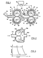
- Figure 1 schematically shows a constant displacement pump in the form of a gear pump motor (10) having successively, in the direction of flow, a compressor section (12), a combustion section (14) and a motor section (16).
- the compression section (12) comprises a casing (18) having inside two toothed wheels (20) which mesh, mounted on shafts (22), and arranged to rotate in the direction of the arrows.
- the drive section (16) has a housing (24) containing two gear wheels (26) which mesh, mounted on the shaft (28), and arranged to rotate in the direction indicated by the arrows.
- the combustion section (14) comprises a combustion chamber (30) having its inlet in communication with the outlet of the compressor (12) and its outlet in communication with the inlet of the drive section (16).
- a combustible gas for example a mixture of a vaporized fuel and air coming from a carburetor (34), enters through an inlet orifice (32) in the compression pump d 'where it is transported in elementary portions in the spaces (36) defined between two contiguous teeth and the inner surface of the housing (18).
- the elementary gas portions are discharged into the communication chamber bustion (30).
- the gas thus introduced into the combustion chamber can simply be air, in which case the fuel is injected directly into the combustion chamber (30) through an orifice (40). Combustion in the combustion chamber (30) is continuous under the conditions of temperature and pressure existing there.
- An ignition device such as a spark plug is installed to start the engine and, if necessary or desired, to maintain combustion during operation.
- the heated and pressurized products of combustion pass through the driving section (24) where they are transported in the spaces (44) between two adjacent teeth (46) and the inner surface of the housing (24).
- the gears (26) are thus moved in the direction of the arrows, and the gas escapes through an outlet orifice (48) to the outside or to another device capable of extracting energy from the gas.
- a certain part of the power obtained from the gears (26) rotated is transferred to the gears of the compressor in order to rotate them, for example by means of a mechanical rotation link (50).
- the value of K for this motor is greater than 1.0.
- An advantage of such an embodiment is that the rotation link (50) can be variable, so that the speed of the pump-compressor (12) relative to the pump-motor (16), is therefore the value of K , can be changed during engine operation to accommodate variations in engine load.
- thermodynamics there is a range of values for the volumetric ratio K defined above, dependent on the operating temperature (the temperature in the combustion chamber), which gives a capacity of output much greater than that envisaged in the preceding conceptions, where the value of K was necessarily bounded, in the interval from zero to one; values greater than unity were expressly excluded.
- the volumetric ratio K must have a value much greater than 1, typically of the order of five or more.
- K for a given motor as in FIG. 1, can be modified during operation, by means of a variable rotation link (50). Such an achievement would make it possible to choose K for the maximum power when the demand demands it and then to increase K to obtain an improved yield under conditions of least effort.
- variable transmission (50) can be controlled by a device (54) capable of measuring the load, so that the speed of the compressor will be increased or decreased relative to the speed of the engine according to a respective decrease or increase in the load, with a consequent increase or decrease of K.
- a device (54) capable of measuring the load, so that the speed of the compressor will be increased or decreased relative to the speed of the engine according to a respective decrease or increase in the load, with a consequent increase or decrease of K.
- Vc small elementary portion of air as it passes through the machine.
- the air portion is compressed to the pressure P 2 of the combustion chamber. Compression takes place quickly and therefore can be considered adiabatic.
- the portion of compressed air undergoes heating at constant pressure in the combustion chamber (2) until it reaches the temperature T 2 of the chamber.
- there is expansion of the portion during the heating phase and in fact it must expand until it reaches the volume Vm of an identical portion of air (heated and mixed with products of combustion) which is leaving the chamber to enter the motor pump (Cepi is a consequence of the constant regime that we have assumed).
- Figure 3 shows the diagram which represents the pressure and the volume of the portion during this process.
- the air enters the compressor at atmospheric pressure at point 1 of the slide. gram. It is compressed adiabatically from 1 to 2 when it is forced into the combustion chamber. Heating takes place at a constant pressure of 2 to 3, the gas expanding due to the addition of thermal energy produced by the combustion of the fuel. Finally, when the gas escapes from the machine, it expands adiabatically from 3 to 4, falling back to atmospheric pressure.
- thermodynamic cycle is that at constant pressure, familiar for example. in gas turbine applications.
- efficiency E of this cycle is equal to where T is the ratio of the specific heats of the air, roughly equal to 1.40.
- Equations (6) and (7) are new, having been obtained for the first time by the applicant, and they form the scientific basis of the invention described in this application.
- Figures 4 and 5 show that an attempt to operate a motor based on constant displacement pumps with a K value ⁇ 1.0, as taught in the prior art, would result in low efficiency and weak power.
- K the power starts to decrease if we go too far. Consequently, for a given motor, we would like to use it with K between fairly well defined limits. For example, for an engine designed for a temperature of 700 ° C, we would not take K greater than about five because of the reduction in power from this value; but it would be reasonable to take K around 4. Similarly, for an engine operating at 1000 ° C we would choose K below 7.5, and, for an engine at 1400'C, below 11.
- V m 50 cm 3 , which (for the gear pump) corresponds to a diameter of the gears of around 13 cm, for a thickness of 2.5 cm.
- V m 50 cm 3 and the same speed, these figures correspond to powers of 2.22 CV and 5.62 CV, respectively.
- the motor (10) may include other features unrelated to the quantity K considered above.
- the teeth (26a) of the gears in the driving part could be in contact with the casing (24a) only on an area close to the outlet of the combustion chamber thus facilitating the cooling of the driving section.
- Zone A of this part, downstream of the contact area between the teeth and the casing could contain a bath or jet of oil through which the teeth pass.
- the housing (24a) can be provided with fins or surrounded by a cooling bath. Cooling by forced air in the axial direction would be possible, especially with spoke gears.
- thicker or larger diameter gears can be used.
- the engine can be started by conventional methods. Starting would be considerably facilitated by means of a simple pipe with an exhaust member forming a decompressor, for example a simple by-pass valve, connected to the combustion chamber allowing the escape of a certain amount of air, thus reducing the pressure. internal during startup.
- a decompressor for example a simple by-pass valve
- the fuel can be introduced into the combustion chamber by various means, for example a carburetor or a nozzle (not shown) placed in the neck.
- the liquid fuels are supplied under high pressure in the chamber (for example around 5000 psi) to ensure good spraying.
- a suitable pump e.g. a small gear pump.
- the ignition can be obtained by an electric spark in the chamber (for example spark plug (42)). Gaseous fuels would be just as useful.
- the engine described above offers considerable advantages over other types of internal combustion engine. It combines the simplicity of the gas turbine with the superior characteristics of piston engines.
- Each of these engines has periods of very high pressure during its operation. As already indicated, in the engine described here, much higher temperatures than 700 ° C are workable, hence a higher yield than that of diesel and gasoline engines of common use.
- the engine described here can operate on a wide variety of fuels, including heavy oils. As the operating temperatures are far below those encountered during part of their cycle by diesel and petrol engines, the production of polluting gases is considerably reduced.
Abstract
Description
Cette invention concerne les moteurs à combustion interne, et en particulier les moteurs du type comprenant successivement une section compresseur, une chambre de combustion à fonctionnement continu, et une section motrice mue par la pression des gaz sortant de la chambre de combustion.This invention relates to internal combustion engines, and in particular to engines of the type comprising successively a compressor section, a combustion chamber with continuous operation, and a driving section driven by the pressure of the gases leaving the combustion chamber.
Des exemples de moteurs du type de la présente invention sont exposés dans les brevets US 3.940.925, 4.012.903 et 3.996.899. La composante essentielle de la section compresseur ainsi que de la section motrice est une pompe à engrenages, c'est-à-dire une pompe formée d'une paire de roues dentées qui s'engrènent et tournent dans un carter, ou bien d'une seule roue dentée qui tourne dans un carter. Dans le cas du compresseur, des portions élémentaires d'un mélange combustible gazeux ou bien simplement d'air, sont acheminées dans les espaces définis par chaque paire de dents adjacentes et la paroi intérieure du carter et se trouvent de cette manière forcées sous pression dans la chambre de combustion. La chambre de combustion fonctionne de façon continue avec ou sans un moyen d'allumage, brûlant soit le mélange gazeux délivré par la section compresseur, soit le mélange qui résulte de l'air délivré par le compresseur et d'un combustible injecté dans la chambre de combustion. Les gaz chauds de combustion, sous pression, passent par la sortie de la chambre de combustion dans l'entrée de la section motrice qui, comme le compresseur, comprend une pompe à engrenages ou bien même une seule roue dentée dans un carter. Les gaz de combustion font tourner les engrenages de la section motrice, qui devient ainsi moteur. Une partie de la puissance ainsi produite est transférée mécaniquement au compresseur pour le faire tourner.Examples of motors of the type of the present invention are set out in US patents 3,940,925, 4,012,903 and 3,996,899. The essential component of the compressor section as well as the drive section is a gear pump, that is to say a pump formed by a pair of toothed wheels which mesh and rotate in a casing, or else a single toothed wheel which turns in a casing. In the case of the compressor, elementary portions of a gaseous combustible mixture or simply of air, are conveyed in the spaces defined by each pair of adjacent teeth and the inner wall of the casing and are thus forced under pressure in the combustion chamber. The combustion chamber operates continuously with or without an ignition means, burning either the gaseous mixture supplied by the compressor section, or the mixture which results from the air supplied by the compressor and from a fuel injected into the chamber. combustion. The hot combustion gases, under pressure, pass through the outlet of the combustion chamber into the inlet of the drive section which, like the compressor, includes a gear pump or even a single toothed wheel in a casing. The combustion gases rotate the gears of the drive section, which becomes motor. Part of the power thus produced is mechanically transferred to the compressor to make it turn.
Aucun moteur du type qu'on vient de décrire n'est utilisé commercialement à la connaissance du demandeur. La raison pour cela est une faute fondamentale dans les conceptions antérieures dépendantes du rapport volumétrique, discutée plus loin, dont le résultat était un rendement inadmissiblement bas.No engine of the type just described is used commercially to the knowledge of the applicant. The reason for this is a fundamental fault in previous conceptions dependent on the volumetric ratio, discussed below, the result of which was an unacceptably low yield.
Ces moteurs, tout comme le moteur qui est l'objet de la présente invention, ont une certaine similarité avec la turbine à gaz (par ex. le moteur à réaction utilisé dans les avions), en ayant les trois phases de compression, combustion, expansion, dans des unités séparées. Cependant, les dynamiques internes de la turbine sont entièrement différentes, dépendant de la quantité de mouvement des molécules de gaz à haute vitesse, plutôt que de la pression interne.These engines, like the engine which is the object of the present invention, have a certain similarity with the gas turbine (eg the jet engine used in airplanes), by having the three phases of compression, combustion, expansion, in separate units. However, the internal dynamics of the turbine are entirely different, depending on the momentum of the gas molecules at high speed, rather than the internal pressure.
Selon les principes du moteur objet de la présente demande, le rendement des moteurs du type décrit antérieurement est énormément augmenté par rapport à celui qui était obtenu avec des moteurs tels que conçus selon l'enseignement antérieur. Les nouvelles conceptions qui rendent possible cette augmentation sont applicables plus généralement à des moteurs basés sur des pompes à déplacement constant, c'est-à-dire moteurs comprenant deux pompes à déplacement constant ayant une chambre de combustion en fonctionnement continu entre les deux. Précisons qu'on entend par pompe à déplacement constant toute pompe volumétrique rotative pour laquelle le déplacement d'un fluide incompressible qui passe par la pompe est sensiblement proportionnel à la rotation angulaire de l'arbre de la pompe. Donc, pour une rotation angulaire donnée de l'arbre, une quantité correspondante d'un fluide incompressible passera par la pompe. La présente invention envisage l'utilisation de pompes à engrenages, au vu de leur simplicité. La nature mécanique des pompes est sans grande importance pourvu que ces pompes satisfassent dans une mesure raisonnable à la définition qu'on vient de donner d'une pompe à déplacement constant.According to the principles of the motor which is the subject of the present application, the efficiency of the motors of the type described previously is enormously increased compared to that which was obtained with motors as designed according to the prior teaching. The new designs which make this increase possible are more generally applicable to motors based on constant displacement pumps, that is to say motors comprising two constant displacement pumps having a combustion chamber in continuous operation therebetween. Note that a constant displacement pump means any rotary positive displacement pump for which the displacement of an incompressible fluid which passes through the pump is substantially proportional to the angular rotation of the pump shaft. Therefore, for a given angular rotation of the shaft, a corresponding quantity of an incompressible fluid will pass through the pump. The present invention contemplates the use of gear pumps, in view of their simplicity. The mechanical nature of the pumps is of little importance as long as these pumps reasonably meet the definition just given of a constant displacement pump.
Dans le présent moteur, comme dans ceux décrits dans les brevets précités, la première pompe comprime l'air, éventuellement mélangé au combustible, le contraignant à passer dans une chambre de combustion où l'allumage aura lieu. Les gaz chauds sous pression ainsi produits et en voie d'expansion passent à la seconde pompe, la faisant tourner et agir comme un moteur. Ce moteur produit une puissance utile et fait également tourner le compresseur moyennant un couplage mécanique. Le présent moteur, toutefois, diffère d'une façon cruciale en ce que le rapport volumétrique de la pompe compresseur à la pompe moteur est beaucoup plus élevé que ce qu'on croyait possible auparavant ; et ce rapport volumétrique plus élevé a pour conséquence un rendement grandement supérieur. Par rapport volumétrique on entend Vc/Vm, où Vc et Vm sont les volumes déplacés respectivement par la pompe compresseur et la pompe moteur pour une rotation de l'arbre moteur d'un angle donné, avec l'hypothèse d'avoir un rapport constant entre les angles de rotation des deux pompes.In the present engine, as in those described in the aforementioned patents, the first pump compresses the air, possibly mixed with the fuel, forcing it to pass into a combustion chamber where the ignition will take place. The hot pressurized gases thus produced and in the process of expansion pass to the second pump, rotating it and acting as a motor. This motor produces useful power and also turns the compressor through mechanical coupling. The present engine, however, differs crucially in that the volumetric ratio of the compressor pump to the engine pump is much higher than previously thought possible; and this higher volumetric ratio results in a much higher yield. By volumetric ratio is meant Vc / Vm, where Vc and Vm are the volumes displaced respectively by the compressor pump and the motor pump for a rotation of the motor shaft by a given angle, with the assumption of having a constant ratio between the angles of rotation of the two pumps.
Donc, ce rapport volumétrique ne dépend ni de l'ampleur de l'angle ni de la vitesse de rotation du moteur. Désormais ce rapport sera noté K, et selon la présente invention K doit toujours être supérieur à 1,0 et de façon pratique devrait être beaucoup plus grand que l'unité, typiquement vers 2,5 pour moteurs ayant une température de chambre de combustion relativement basse (par exemplé 700*C ) et 5,0 ou plus pour moteurs opérant à des températures de chambre de combustion assez élevées (par exemple 1400*C). La valeur de K n'est point arbitraire. Pourtant, comme on verra dans ce qui suit, les valeurs appropriées de K dépendent de la température de fonctionnement du moteur et de l'application des principes de la thermodynamique à ce moteur, d'où il résultera que K a une certaine gamme de valeurs pour lesquelles le rendement et la puissance sont optimaux.Therefore, this volumetric ratio does not depend on the magnitude of the angle or on the speed of rotation of the engine. From now on this ratio will be denoted K, and according to the present invention K must always be greater than 1.0 and in practice should be much larger than the unit, typically around 2.5 for engines having a relatively combustion chamber temperature. low (for example 700 * C) and 5.0 or more for engines operating at fairly high combustion chamber temperatures (for example 1400 * C). The value of K is not arbitrary. However, as will be seen below, the appropriate values of K depend on the engine operating temperature and on the application of the principles of thermodynamics to this engine, from which it will result that K has a certain range of values for which performance and power are optimal.
Les brevets US précités ne font pas usage du terme "rapport volumétrique", mais font appel à une terminologie qui inéluctablement mène à des valeurs de K < 1.The aforementioned US patents do not use the term "volumetric ratio", but use terminology which inevitably leads to values of K <1.
Nous désignons par K le rapport volumétrique, K = Vc/Vm, c'est-à-dire, le rapport du déplacement Vc du compresseur au déplacement Vm du moteur lorsque l'arbre du moteur effectue une rotation d'un certain angle. Bien entendu, le rapport ne dépend pas de la grandeur de cet angle. Les enseignements des configurations de la technique antérieure mènent inévitablement à des valeurs K < 1, valeurs qui ne sont pas précisées autrement. Bien que le terme rapport volumétrique ne figure pas dans les brevets US précité., il y est dit clairement que le moteur doit être tel que le rapport K soit inférieur à l'unité. Le brevet 4.012.903 déclare que la surface de travail des roues dentées motrices est supérieure à celle des roues du compresseur, de sorte que l'explosion des gaz dans la chambre de combustion agit toujours de façon à faire avancer les roues motrices, au lieu d'arrêter le moteur en agissant sur les roues du compresseur. Le brevet 3.996.899 spécifie que le compresseur doit tourner à une vitesse volumétrique inférieure à celle dudit moteur. Le brevet 3.940.925 déclare que les gaz explosants exercent aussi quelques forces contre les engrenages du compresseur et tendent donc à produire une rotation dans le sens contraire à celui souhaité. Donc l'aire des engrenages du moteur sur laquelle la pression des gaz d'explosion agit est plus grande que l'aire des engrenages du compreseur dans un rapport proportionnel aux largeurs des engrenages. Donc dans tous les cas le rapport volumétrique doit être inférieur à l'unité à cause de la contre pression qui, dans l'esprit des demandeurs précédents, tendrait autrement à faire tourner le compresseur à contresens, empêchant le fonctionnement du moteur.We denote by K the volumetric ratio, K = Vc / Vm, that is to say, the ratio of the displacement Vc of the compressor to the displacement Vm of the motor when the motor shaft rotates by a certain angle. Of course, the ratio does not depend on the magnitude of this angle. The teachings of the configurations of the prior art inevitably lead to values K <1, values which are not otherwise specified. Although the term volumetric ratio does not appear in the aforementioned US patents, it is clearly stated therein that the engine must be such that the ratio K is less than unity. Patent 4,012,903 declares that the working surface of the driving gear wheels is greater than that of the compressor wheels, so that the explosion of gases in the combustion chamber always acts so as to advance the driving wheels, instead stop the engine by acting on the compressor wheels. Patent 3,996,899 specifies that the compressor must rotate at a volumetric speed lower than that of said motor. Patent 3,940,925 declares that the exploding gases also exert some forces against the gears of the compressor and therefore tend to produce a rotation in the opposite direction to that desired. Therefore, the area of the engine gears on which the pressure of the explosion gases acts is greater than the area of the compressor gears in a ratio proportional to the widths of the gears. So in all cases the volumetric ratio must be less than unity because of the back pressure which, in the minds of the preceding applicants, would otherwise tend to turn the compressor in the opposite direction, preventing the operation of the engine.
Cette conclusion est le résultat d'une conception fondamentalement erronée. Le présent demandeur a découvert moyennant une analyse entièrement nouvelle des processus que des valeurs de K bien supérieures à l'unité sont non seulement possibles mais sont en effet essentielles pour atteindre des niveaux pratiques de rendement. Cela est loin d'être évident et n'apparaît qu'à travers les équations du demandeur. Donc, pour la première fois le moteur basé sur des pompes à déplacement constant devient un moteur pratique, rivalisant en rendement avec les moteurs Diesel et à essence usuels, tout en offrant des avantages significatifs sur les deux.This conclusion is the result of a fundamentally flawed conception. The present applicant has discovered through an entirely new process analysis that values of K much greater than unity are not only possible but are indeed essential for achieving practical levels of performance. This is far from obvious and only appears through the applicant's equations. Therefore, for the first time the engine based on constant displacement pumps becomes a practical engine, competing in performance with the usual Diesel and petrol engines, while offering significant advantages on both.
Le problème de la contre-pression envisagée dans l'enseignement de l'art antérieur s'est montré inexistant. La raison n'est pas évidente ; c'est peut-être que le gaz en voie d'entrer dans la chambre de combustion agit comme un coussin, de sorte que la pression maximale de la chambre n'agit pas sur le compresseur.
- - La figure 1 représente schématiquement une coupe d'un moteur basé sur les pompes à déplacement constant, conforme à la présente invention ;
- - la figure 2 est une coupe schématique d'une autre réalisation de la section motrice ;
- - la figure 3 est le graphique de la pression par rapport au volume d'une portion élémentaire de gaz passant par le moteur de la figure 1;
- - la figure 4 est un graphique du rendement par rapport aux valeurs de K; et
- - la figure 5 est un graphique de la puissance effective par rapport à K en unité arbitraire.
- - Figure 1 shows schematically a section of an engine based on constant displacement pumps, according to the present invention;
- - Figure 2 is a schematic section of another embodiment of the drive section;
- - Figure 3 is the graph of the pressure relative to the volume of an elementary portion of gas passing through the engine of Figure 1;
- FIG. 4 is a graph of the yield with respect to the values of K; and
- - Figure 5 is a graph of the effective power with respect to K in arbitrary units.
La figure 1 montre schématiquement une pompe à déplacement constant dans la forme d'un moteur à pompes à engrenages (10) ayant successivement, dans le sens du flux, une section compresseur (12), une section combustion (14) et une section motrice (16). La section de compression (12) comprend un carter (18) ayant à l'intérieur deux roues dentées (20) qui s'engrènent, montées sur arbres (22), et agencées pour tourner dans le sens des flèches. De manière similaire, la section motrice (16) comporte un carter (24) contenant deux roues dentées (26) qui s'engrènent, montées sur arbre (28), et agencées pour tourner dans le sens indiqué par les flèches. La section combustion (14) comprend une chambre de combustion (30) ayant son entrée en communication avec la sortie du compresseur (12) et sa sortie en communication avec l'entrée de la section motrice (16).Figure 1 schematically shows a constant displacement pump in the form of a gear pump motor (10) having successively, in the direction of flow, a compressor section (12), a combustion section (14) and a motor section (16). The compression section (12) comprises a casing (18) having inside two toothed wheels (20) which mesh, mounted on shafts (22), and arranged to rotate in the direction of the arrows. Similarly, the drive section (16) has a housing (24) containing two gear wheels (26) which mesh, mounted on the shaft (28), and arranged to rotate in the direction indicated by the arrows. The combustion section (14) comprises a combustion chamber (30) having its inlet in communication with the outlet of the compressor (12) and its outlet in communication with the inlet of the drive section (16).
Durant le fonctionnement du moteur (10) un gaz combustible, par exemple un mélange d'un carburant vaporisé et d'air venant d'un carburateur (34), entre par un orifice d'admission (32) dans la pompe à compression d'où il est transporté en portions élémentaires dans les espaces (36) définis entre deux dents contigües et la surface intérieure du carter (18). A l'orifice de sortie du carter les portions élémentaires de gaz sont déchargées dans la chambre de combustion (30). Le gaz ainsi introduit dans la chambre de combustion peut être simplement de l'air, auquel cas le carburant est injecté directement dans la chambre de combustion (30) par un orifice (40). La combustion dans la chambre de combustion (30) est continue dans les conditions de température et de pression y existant. Un dispositif d'allumage tel qu'une bougie est installé pour le démarrage du moteur et, si nécessaire ou désiré, pour maintenir la combustion pendant la marche. Les produits de combustion chauffés et sous pression passent dans la section motrice (24) où ils sont transportés dans les espaces (44) entre deux dents adjacentes (46) et la surface intérieure du carter (24). Les engrenages (26) sont ainsi mùs dans le sens des flèches, et le gaz s'échappe par un orifice de sortie (48) vers l'extérieur ou vers un autre dispositif susceptible d'extraire l'énergie du gaz. Une certaine partie de la puissance obtenue des engrenages (26) mis en rotation est transférée aux engrenages du compresseur afin de faire tourner ceux-ci, par exemple au moyen d'une liaison en rotation mécanique (50).During the operation of the engine (10) a combustible gas, for example a mixture of a vaporized fuel and air coming from a carburetor (34), enters through an inlet orifice (32) in the compression pump d 'where it is transported in elementary portions in the spaces (36) defined between two contiguous teeth and the inner surface of the housing (18). At the outlet of the crankcase the elementary gas portions are discharged into the communication chamber bustion (30). The gas thus introduced into the combustion chamber can simply be air, in which case the fuel is injected directly into the combustion chamber (30) through an orifice (40). Combustion in the combustion chamber (30) is continuous under the conditions of temperature and pressure existing there. An ignition device such as a spark plug is installed to start the engine and, if necessary or desired, to maintain combustion during operation. The heated and pressurized products of combustion pass through the driving section (24) where they are transported in the spaces (44) between two adjacent teeth (46) and the inner surface of the housing (24). The gears (26) are thus moved in the direction of the arrows, and the gas escapes through an outlet orifice (48) to the outside or to another device capable of extracting energy from the gas. A certain part of the power obtained from the gears (26) rotated is transferred to the gears of the compressor in order to rotate them, for example by means of a mechanical rotation link (50).
Selon l'invention, la valeur de K pour ce moteur, comme on a dit plus haut, est supérieure à 1,0. Cela est facilement réalisé en construisant la liaison en rotation (50) de manière à faire tourner la pompe-compresseur (12) pour obtenir une valeur de Vc plus grande que Vm, c'est-à-dire à une vitesse de rotation supérieure à celle de la pompe moteur (16), en s'assurant d'avoir les deux pompes identiques. Un avantage d'une telle réalisation est que la liaison en rotation (50) peut être variable, de sorte que la vitesse de la pompe-compresseur (12) par rapport à la pompe-moteur (16), est donc la valeur de K, peuvent être modifiées pendant le fonctionnement du moteur pour accommoder les variations de la charge du moteur. La construction de la pompe-compresseur avec un déplacement supérieur à celui de la pompe-moteur donnera un moteur à grand K fixe, si la vitesse des deux pompes sont supposées égales, ce qui pourrait suffire pour certains moteurs. Mais une liaison en rotation variable est aussi avantageuse dans ce cas.According to the invention, the value of K for this motor, as said above, is greater than 1.0. This is easily achieved by constructing the rotary link (50) so as to rotate the pump-compressor (12) to obtain a value of Vc greater than Vm, that is to say at a speed of rotation greater than that of the motor pump (16), ensuring that the two pumps are identical. An advantage of such an embodiment is that the rotation link (50) can be variable, so that the speed of the pump-compressor (12) relative to the pump-motor (16), is therefore the value of K , can be changed during engine operation to accommodate variations in engine load. The construction of the pump-compressor with a displacement greater than that of the pump-motor will give a motor with large fixed K, if the speed of the two pumps are supposed to be equal, which could be sufficient for certain motors. But a link in variable rotation is also advantageous in this case.
on comprendra que le moteur (10) a été décrit dans une forme simplifiée pour mieux illustrer ses principes de base. Dans la pratique, le moteur aurait divers dispositifs de contrôle, et la section de compression, la chambre de combus- tion et la section motrice pourraient être beaucoup plus complexes.it will be understood that the motor (10) has been described in a simplified form to better illustrate its basic principles. In practice, the engine would have various control devices, and the compression section, the combus- chamber t i n and the driving section may be much more complex.
Tous les ingrédients ci-dessus, à l'exception du rôle de K, et donc du rapport entre la section compresseur et la section motrice, sont connus dans l'état de l'art. La présente invention est basée sur la découverte, par des principes fondamentaux de la thermodynamique, et par un choix convenable. des paramètres, considérés impossible dans l'art antérieur, de la possibilité de produire un haut rendement sur un moteur utilisant des pompes à déplacement constant. Plus spécifiquement, la présente invention démontre, en faisant appel à la thermodynamique, qu'il y a une étendue de valeurs pour le rapport volumétrique K défini plus haut, dépendant de la température de fonctionnement (la température dans la chambre de combustion), qui donne une capacité de rendement beaucoup plus grande que celle envisagée dans les conceptions précédentes, où la valeur de K était nécessairement bornée, dans l'intervalle de zéro à un ; les valeurs supérieures à l'unité étaient expressément exclues. Dans la présente demande il est démontré que le rapport volumétrique K doit avoir une valeur bien supérieure à 1, typiquement de l'ordre de cinq ou plus.All the above ingredients, with the exception of the role of K , and therefore of the relationship between the compressor section and the power section, are known in the state of the art. The present invention is based on discovery, by fundamental principles of thermodynamics, and by a suitable choice. parameters, considered impossible in the prior art, of the possibility of producing a high efficiency on an engine using constant displacement pumps. More specifically, the present invention demonstrates, using thermodynamics, that there is a range of values for the volumetric ratio K defined above, dependent on the operating temperature (the temperature in the combustion chamber), which gives a capacity of output much greater than that envisaged in the preceding conceptions, where the value of K was necessarily bounded, in the interval from zero to one; values greater than unity were expressly excluded. In the present application it is demonstrated that the volumetric ratio K must have a value much greater than 1, typically of the order of five or more.
Des limites précises pour la gamme des valeurs utiles de K, dépendantes des conditions de fonctionnement, sont déterminées essentiellement par la température de fonctionnement. Entre ces limites la valeur de K choisie détermine le rendement et la puissance, les plus hautes valeurs de K donnant un rendement accru mais aux dépens de la puissance disponible, les valeurs de K plus basses fournissant plus de puissance mais au prix d'un rendement réduit. Aussi, K pour un moteur donné, comme dans la figure 1, peut être modifié pendant le fonctionnement, moyennant une liaison en rotation (50) variable. Une telle réalisation permettrait de choisir K pour la puissance maximale lorsque la demande l'exige et puis d'augmenter K pour obtenir un rendement amélioré dans des conditions de moindre effort. A cette fin la transmission variable (50) peut être contrôlée par un dispositif (54) susceptible de mesurer la charge, de sorte que la vitesse du compresseur sera augmentée ou diminuée par rapport à la vitesse du moteur suivant une diminution ou augmentation respective de la charge, avec une conséquente augmentation ou diminution de K. Cette possibilité a une utilité particulière lorsque le moteur fonctionne avec des valeurs de K comprises entres les droites A et B sur la figure 5. Cet intervalle de valeurs sera analysé plus loin.Precise limits for the range of useful values of K, dependent on the operating conditions, are determined essentially by the operating temperature. Between these limits the value of K chosen determines the efficiency and the power, the highest values of K giving an increased efficiency but at the expense of the available power, the lower values of K providing more power but at the cost of an efficiency reduced. Also, K for a given motor, as in FIG. 1, can be modified during operation, by means of a variable rotation link (50). Such an achievement would make it possible to choose K for the maximum power when the demand demands it and then to increase K to obtain an improved yield under conditions of least effort. To this end, the variable transmission (50) can be controlled by a device (54) capable of measuring the load, so that the speed of the compressor will be increased or decreased relative to the speed of the engine according to a respective decrease or increase in the load, with a consequent increase or decrease of K. This possibility has a particular utility when the engine works with values of K included between the lines A and B on figure 5. This interval of values will be analyzed later.
Maintenant on passe à l'analyse thermodynamique du moteur, sous l'hypothèse usuelle que le régime est constant (cf. fig. 3).Now we go to the thermodynamic analysis of the engine, under the usual assumption that the speed is constant (cf. fig. 3).
De l'air sans carburant, entre dans le compresseur (1) à pression ambiante Pi et à température ambiante Ti. Nous suivons la progression d'une petite portion élémentaire Vc d'air lorsqu'elle passe par la machine. Entrant dans la première pompe à déplacement constant, la portion d'air est comprimée jusqu'à la pression P2 de la chambre de combustion. La compression a lieu rapidement et donc peut être considérée comme adiabatique. Ensuite la portion d'air comprimé subit un chauffage à pression constante dans la chambre de combustion (2) jusqu'à ce qu'elle atteigne la température T2 de la chambre. Bien entendu, il y a expansion de la portion pendant la phase de chauffage, et en fait elle doit se dilater jusqu'à ce qu'elle atteigne le volume Vm d'une portion identique d'air (chauffée et mélangée avec des produits de combustion) qui est en train de quitter la chambre pour entrer dans la pompe motrice (Cepi est une conséquence du régime constant que nous avons supposé). Enfin, la portion d'air sous étude est libérée à l'atmosphère, où elle retourne adiabatiquement à la pression ambiante Pi. La figure 3 montre le diagramme qui représente la pression et le volume de la portion pendant ce processus. Dans ce cycle, l'air entre dans le compresseur à la pression atmosphérique au point 1 du diagramme. Il est comprimé adiabatiquement de 1 à 2 quand il est forcé dans la chambre de combustion. Le chauffage a lieu à pression constante de 2 à 3, le gaz se dilatant à cause de l'addition d'énergie thermique produite par la combustion du carburant. Enfin, quand le gaz s'échappe de la machine, il se dilate adiabatiquement de 3 à 4, retombant à la pression atmosphérique.Air without fuel enters the compressor (1) at ambient pressure Pi and at ambient temperature Ti. We follow the progress of a small elementary portion Vc of air as it passes through the machine. Entering the first constant displacement pump, the air portion is compressed to the pressure P 2 of the combustion chamber. Compression takes place quickly and therefore can be considered adiabatic. Then the portion of compressed air undergoes heating at constant pressure in the combustion chamber (2) until it reaches the temperature T 2 of the chamber. Of course, there is expansion of the portion during the heating phase, and in fact it must expand until it reaches the volume Vm of an identical portion of air (heated and mixed with products of combustion) which is leaving the chamber to enter the motor pump (Cepi is a consequence of the constant regime that we have assumed). Finally, the portion of air under study is released to the atmosphere, where it adiabatically returns to ambient pressure Pi. Figure 3 shows the diagram which represents the pressure and the volume of the portion during this process. In this cycle, the air enters the compressor at atmospheric pressure at
Ici bien entendu on a fait usage des approximations usuelles dans l'analyse des machines thermiques. On notera que le cycle thermodynamique est celui à pression constante, familier par ex. dans les applications aux turbines à gaz. Le rendement E de ce cycle, comme il est démontré dans la science de la thermodynamique est égal à![]()
![]()
Pour aller plus loin nous aurons besoin de quelques faits de la thermodynamique, d'abord l'équation d'état PV = RT bien connue, où V désigne le volume d'une quantité de gaz, P sa pression, T sa température absolue; R est une constante qui dépend des unités choisies.To go further we will need some facts from thermodynamics, first the well-known equation of state PV = RT, where V denotes the volume of a quantity of gas, P its pressure, T its absolute temperature; R is a constant which depends on the units chosen.
Retournant à la portion d'air Vc, nous avons avant compression PiVc = RTi. Après expansion dans la chambre de combustion cette relation devient P2Vm = RTz. En rapportant la première de ces relations à la seconde, le facteur R disparaît, et il en résulte![]()
![]()
Nous rappelons que le rapport volumétrique est![]()
![]()
Donc l'équation précédente peut s'écrire![]()
![]()
Ensuite considérons un gaz qui subit une compression adiabatique de l'état Pi, Vi à l'état P2, Vz. Nous avons alors la relation connue

![]()
![]()
Donc p = Kt, d'après (3), et il s'ensuit que le travail Wc fourni par le compresseur peut s'écrire
Ce travail est fourni par le moteur. Le travail total Wm fourni par le moteur dans l'intervalle de temps considéré est Wm = P2Vm = KPiVmt, à l'aide de (3). Le travail net est donc
- W = Wm -
W
- W = Wm - W c = 2.5 kP 1 V m (0.4t - K c t c + 1) (6)
Le rendement (1) peut maintenant s'écrire
Les équations (6) et (7) sont nouvelles, ayant été obtenues pour la première fois par le demandeur, et elles forment la base scientifique de l'invention décrite dans cette demande.Equations (6) and (7) are new, having been obtained for the first time by the applicant, and they form the scientific basis of the invention described in this application.
Les équations sont des approximations, comme c'est toujours le cas dans l'analyse des machines thermiques parce qu'elles seront affectées dans une certaine mesure par la sollicitation du moteur et par des changements de vitesse et aussi parce que le cycle n'est pas strictement à pression constante.The equations are approximations, as is always the case in the analysis of thermal machines because they will be affected to some extent by the stress of the engine and by speed changes and also because the cycle is not not strictly at constant pressure.
A l'aide des équations (6) et (7) il est possible de faire des calculs et d'illustrer les résultats graphiquement. On suppose que le moteur auquel on applique les calculs est de taille suffisante pour brûler assez de carburant pour produire la puissance indiquée dans les calculs. D'abord choisissons trois valeurs typiques du rapport t des températures comme suit :
- t = 3,38, correspondant à une température Tz de 700'C dans la chambre de combustion
- t = 4,42, correspondant à une température Tz de 1000°C dans la chambre de combustion
- t = 5,81, correspondant à une température Tz de 1400*C dans la chambre de combustion
- t = 3.38, corresponding to a temperature Tz of 700 ° C in the combustion chamber
- t = 4.42, corresponding to a temperature Tz of 1000 ° C in the combustion chamber
- t = 5.81, corresponding to a temperature Tz of 1400 * C in the combustion chamber
Pour chaque valeur de t calculons une série de valeurs de W (puissance nette) de l'équation (6) utilisant pour chaque calcul diverses valeurs de K, disons entre 1,0 et 12,0. Le facteur 2,5 PiVm peut être laissé de côté sans affecter la discussion. Les résultats de ces calculs sont présentés graphiquement dans la figure 5, où l'abscisse est K, l'ordonnée étant la puissance disponible W. On voit tout de suite que la puissance s'accroît avec K jusqu'à ce qu'elle atteigne un maximum, et puis décroît lorsque K augmente davantage. La valeur de K qui donne la puissance maximale croît avec la température de la chambre de combustion.For each value of t let us calculate a series of values of W (net power) of equation (6) using for each calculation various values of K, say between 1.0 and 12.0. The factor 2.5 PiVm can be left out without affecting the discussion. The results of these calculations are presented graphically in Figure 5, where the abscissa is K, the ordinate being the available power W. We immediately see that the power increases with K until it reaches a maximum, and then decreases when K increases further. The value of K which gives the maximum power increases with the temperature of the combustion chamber.
Si l'on effectue les calculs avec l'équation (7) on obtient les résultats présentés à la figure 4, où l'abscisse est encore K, l'ordonnée étant le rendement. Ces graphiques montrent que le rendement croît avec K, mais non linéairement.If one carries out the calculations with equation (7) one obtains the results presented in figure 4, where the abscissa is still K, the ordinate being the yield. These graphs show that the yield increases with K, but not linearly.
Les figures 4 et 5 montrent qu'une tentative de faire fonctionner un moteur basé sur des pompes à déplacement constant avec une valeur K < 1,0, comme il a été enseigné dans l'art antérieur, aurait comme résultat un bas rendement et une faible puissance. Lorsqu'on augmente K la puissance commence à décroître si l'on va trop loin. Par conséquent, pour un moteur donné on voudrait s'en servir avec K compris entre des limites assez bien définies. Par exemple, pour un moteur conçu pour une température de 700°C, on ne prendrait pas K plus grand que cinq environ à cause de la réduction de la puissance à partir de cette valeur; mais il serait raisonnable de prendre K autour de 4. De même, pour un moteur qui fonctionne à 1000°C on choisirait K au-dessous de 7,5, et, pour un moteur à 1400'C, au-dessous de 11.Figures 4 and 5 show that an attempt to operate a motor based on constant displacement pumps with a K value <1.0, as taught in the prior art, would result in low efficiency and weak power. When we increase K the power starts to decrease if we go too far. Consequently, for a given motor, we would like to use it with K between fairly well defined limits. For example, for an engine designed for a temperature of 700 ° C, we would not take K greater than about five because of the reduction in power from this value; but it would be reasonable to take K around 4. Similarly, for an engine operating at 1000 ° C we would choose K below 7.5, and, for an engine at 1400'C, below 11.
Typiquement on serait enclin à choisir, suivant les graphiques de la figure 5, des valeurs de K entre celle qui correspond à la puissance maximum (c'est-à-dire Kmax) et une valeur supérieure qui donne encore une puissance acceptable, soit 1,5Kmax ou 2Kmax. En adoptant cette règle, une gamme raisonnable pour les valeurs de K serait dans l'aire entre les droites A et B (fig. 5). A gauche de la droite A la puissance et le rendement baissent; à droite de B la puissance baisse sans une grande augmentation du rendement jusqu'à s'annuler pour des valeurs critiques de K correspondant à sa limite supérieure KLIN propre à chaque température de fonctionnement du moteur. Allons un peu au dessous de cette valeur critique. Alors il y a très peu de puissance disponible sur l'arbre; la plus grande partie de l'énergie disponible réside dans les gaz chauds et assez fortement comprimés qui sortent de la pompe motrice à haute vitesse. Avantageusement, ces gaz peuvent servir entre autres pour la propulsion à réaction. C'est ce qui a lieu dans un moteur à réaction classique, qui n'est autre chose qu'une turbine à gaz dont seulement une faible partie de la puissance est extraite sur l'arbre, pour dynamos, etc.Typically we would be inclined to choose, according to the graphs in FIG. 5, values of K between that which corresponds to the maximum power (that is to say Kmax) and a higher value which still gives an acceptable power, either 1.5K max or 2K max . By adopting this rule, a reasonable range for the values of K would be in the area between the lines A and B (fig. 5). To the left of the right To the power and the yield decrease; to the right of B the power drops without a large increase in efficiency until it is canceled out for critical values of K corresponding to its upper limit K LIN specific to each operating temperature of the engine. Let's go a little below this critical value. So there is very little power available on the shaft; most of the available energy resides in the hot and fairly strongly compressed gases which exit the motor pump at high speed. Advantageously, these gases can be used inter alia for jet propulsion. This is what takes place in a conventional jet engine, which is nothing more than a gas turbine from which only a small part of the power is extracted from the shaft, for dynamos, etc.
Des équations (6) et (7) on peut obtenir l'équation suivante. pour Kmax:![]()
![]()
On peut effectuer les calculs sous des hypothèses pratiques. On trouve de grandes turbines à gaz qui fonctionnent avec une température d'environ 700°C dans la chambre de combustion, et nous commencerons avec ce cas de figure. Alors T1 = 15'C = 288°K, Tz = 973°K, (ici K siginifie Kelvin) d'où![]()
![]()
Nous prenons t = 1,40, donc c = 0,286. De (6) le travail net fourni est![]()
![]()
Bien entendu il faut avoir W > 0, ce qui donne la condition![]()
![]()
commençons avec K = 5. Il résulte![]()
![]()
On obtient la puissance maximum avec K = 2,42, et alors nous avons![]()
![]()
Pour un petit moteur on pourrait prendre par ex. Vm = 50 cm3, ce qui (pour la pompe à engrenages) correspond à un diamètre des engrenages de quelque 13 cm, pour une épaisseur de 2,5 cm. Prenons comme vitesse 5000 tours/minute = 83,33 tours/seconde. Alors nous obtenons (Pi = 1,152 kg/cm2)![]()
![]()
Multipliant par la vitesse, nous arrivons à![]()
![]()
Si l'on fait le même calcul avec K = 2,42, la puissance est égale à 2,01 CV.If we do the same calculation with K = 2.42, the power is equal to 2.01 CV.
Des températures bien plus élevées sont possibles, et de nombreux moteurs d'avions à réaction (leurs moteurs sont des des turbines à gaz) fonctionnent avec une température de combustion de 1400'C ou plus. Avec ce chiffre, nous avons t = 5,81. Nous trouvons que dans ce cas K ne peut pas dépasser 11,6. Pour K = 10 nous avons![]()
![]()
La puissance maximale est fournie par K = 4,81, et alors![]()
![]()
Avec le même Vm = 50 cm3 et la même vitesse, ces chiffres correspondent à des puissances de 2,22 CV et 5,62 CV, respectivement.With the
On voit que le prix d'un haut rendement est une réduction de puissance, qu'on peut compenser en augmentant la vitesse ou Vm. Bien sûr, il y a des limites. On devrait tenir compte du fait que rendement ici signifie rendement idéal, écartant les pertes dues au frottement, à la turbulence dans la chambre, etc. Des fuites dans les pompes à engrenages réduiraient le rendement. Mais avec des pompes de bonne construction ce facteur devrait être minime, par contraste avec le cas de la turbine à gaz. Dans les machines thermiques pratiques, les pertes que nous avons laissées de côté, bien qu'importantes dans le fonctionnement, sont petites en comparaison avec les pertes inévitables imposées par les lois de la thermodynamique.We see that the price of a high efficiency is a reduction in power, which can be compensated by increasing the speed or Vm. Of course, there are limits. One should take into account that efficiency here means ideal efficiency, excluding losses due to friction, turbulence in the chamber, etc. Leaks in gear pumps would reduce performance. But with pumps of good construction this factor should be minimal, in contrast to the case of the gas turbine. In practical thermal machines, the losses that we have left out, well that important in operation, are small in comparison with the inevitable losses imposed by the laws of thermodynamics.
Nous terminons nos exemples par le calcul de la pression interne Pz, utilisant (2) avec Pi = 1,152 kg/cm2. Pour le premier cas, t = 3,38, nous avons Pz = 19,3 kg/cm2 pour K = 5, et Pz = 9,36 kg/cm2 pour K = 2,42. Pour le cas de 1400'C, t = 4,81, nous obtenons Pz = 66,5 kg/cm2 quand K = 10, Pz = 29,95 kg/cm2 pour K = 4,81. Ces pressions sont loin d'être extrêmes.We end our examples by calculating the internal pressure Pz, using (2) with Pi = 1.152 kg / cm 2 . For the first case, t = 3.38, we have Pz = 19.3 kg / cm 2 for K = 5, and Pz = 9.36 kg / cm 2 for K = 2.42. For the case of 1400'C, t = 4.81, we obtain Pz = 66.5 kg / cm 2 when K = 10, Pz = 29.95 kg / cm 2 for K = 4.81. These pressures are far from extreme.
Selon d'autres considérations, le moteur (10) peut comporter d'autres particularités sans rapport avec la quantité K considérée plus haut. Par exemple (fig. 2) les dents (26a) des engrenages dans la partie motrice pourraient être en contact avec le carter (24a) seulement sur une zone proche de la sortie de la chambre de combustion facilitant ainsi le refroidissement de la section motrice. La zone A de cette partie, en aval de l'aire de contact entre les dents et le carter pourrait contenir un bain ou jet d'huile par lequel passent les dents. Le carter (24a) peut être muni d'ailettes ou entouré d'un bain refroidissant. Un refroidissement au moyen d'air forcé dans la direction axiale serait possible, surtout avec des engrenages à rayons. Pour augmenter le déplacement du moteur ou du compresseur, on peut se servir d'engrenages plus épais ou de grand diamètre. Rien n'exclut l'emploi d'engrenages très épais, auquel cas ils ressembleraient à des rouleaux et l'on parlerait plutôt de leur longueur que de leur épaisseur. De cette manière il serait possible de maintenir les forces centrifuges à un niveau acceptable dans certaines applications. Bien que des engrenages ordinaires figurent dans les dessins, il est possible dans certains cas, que des engrenages coniques, par exemple, aient un avantage mécanique. Il est également possible d'utiliser des engrenages hélicoïdaux pour avoir un fonctionnement plus régulier et plus silencieux. On notera aussi que le nombre de dents peut être aussi petit que deux (le compresseur du type Roots). En fait, avec une palette coulissante on peut avoir une seule "dent", comme dans le compresseur Rollator.According to other considerations, the motor (10) may include other features unrelated to the quantity K considered above. For example (fig. 2) the teeth (26a) of the gears in the driving part could be in contact with the casing (24a) only on an area close to the outlet of the combustion chamber thus facilitating the cooling of the driving section. Zone A of this part, downstream of the contact area between the teeth and the casing could contain a bath or jet of oil through which the teeth pass. The housing (24a) can be provided with fins or surrounded by a cooling bath. Cooling by forced air in the axial direction would be possible, especially with spoke gears. To increase the displacement of the motor or compressor, thicker or larger diameter gears can be used. Nothing precludes the use of very thick gears, in which case they would look like rollers and we would rather speak of their length than their thickness. In this way it would be possible to maintain the centrifugal forces at an acceptable level in certain applications. Although ordinary gears are shown in the drawings, it is possible in some cases that bevel gears, for example, have a mechanical advantage. It is also possible to use helical gears to have a more regular and quieter operation. It should also be noted that the number of teeth can be as small as two (the compressor of the type Roots). In fact, with a sliding pallet you can have only one "tooth", as in the Rollator compressor.
Quant à la chambre de combustion pour le moteur décrit ci-dessus, celles du type utilisé couramment dans les turbines à gaz seraient certainement adéquates. Ces chambres ont un goulet au bout vers le compresseur et se terminent en un ajutage à l'autre bout ; cette caractéristique est reférencée (52) sur la figure 1. Dans la présente invention, l'ajutage serait probablement modifié afin de réduire la turbulence dans la chambre de combustion, considération non sans importance à cause des pertes d'énergie qui en résultent. Pour la même raison il serait utile d'installer des vannes près des orifices d'entrée du compresseur et du moteur, au lieu de permettre l'air de rencontrer de front et à haute vitesse les dents avançantes.As for the combustion chamber for the engine described above, those of the type commonly used in gas turbines would certainly be adequate. These chambers have a neck at the end towards the compressor and end in a nozzle at the other end; this characteristic is referenced (52) in FIG. 1. In the present invention, the nozzle would probably be modified in order to reduce the turbulence in the combustion chamber, a consideration which is not unimportant because of the resulting energy losses. For the same reason it would be useful to install valves near the inlet ports of the compressor and the engine, instead of allowing air to meet the advancing teeth head-on and at high speed.
Le démarrage du moteur peut être assuré par des méthodes usuelles. Le démarrage serait considérablement facilité moyennant une simple canalisation avec un organe d'échappement formant décompresseur, par exemple une simple valve by-pass, reliée à la chambre de combustion permettant l'échappement d'une certaine quantité d'air, réduisant ainsi la pression interne pendant le démarrage.The engine can be started by conventional methods. Starting would be considerably facilitated by means of a simple pipe with an exhaust member forming a decompressor, for example a simple by-pass valve, connected to the combustion chamber allowing the escape of a certain amount of air, thus reducing the pressure. internal during startup.
Le carburant peut être introduit dans la chambre de combustion par divers moyens par exemple un carburateur ou un ajutage (non représenté) placé dans le goulet. Dans ce cas les carburants liquides sont fournis sous haute pression dans la chambre (par exemple environ 5000 psi) pour assurer une bonne pulvérisation. Naturellement avec une injection du carburant il faut une pompe adéquate, par ex. une petite pompe à engrenages. L'allumage peut être obtenu par une étincelle électrique dans la chambre (par exemple bougie d'allumage (42)). Les carburants gazeux seraient tout aussi utiles.The fuel can be introduced into the combustion chamber by various means, for example a carburetor or a nozzle (not shown) placed in the neck. In this case the liquid fuels are supplied under high pressure in the chamber (for example around 5000 psi) to ensure good spraying. Of course with fuel injection you need a suitable pump, e.g. a small gear pump. The ignition can be obtained by an electric spark in the chamber (for example spark plug (42)). Gaseous fuels would be just as useful.
Le moteur décrit plus haut offre des avantages considérables sur les autres types de moteur à combustion interne. Il unit la simplicité de la turbine à gaz avec les caractéristiques supérieures des moteurs à piston. Le rendement (idéal) des turbines à gaz est typiquement inférieur à 25% à une température de combustion autour de 700°C contre 45% pour le moteur ici traité (fonctionnant au régime de puissance maximale). Il est utile de comparer le présent moteur avec le moteur à essence (cycle Otto) et le moteur Diesel. Dans les moteurs à essence, le rapport de compression C ne peut normalement dépasser huit ou neuf. Pour C = 6 le rendement est de 51% et pour C = 7 il est de 55%. Le moteur Diesel avec C = 14 produit un rendement de 55%, et de 59% pour C = 16. Chacun de ces moteurs a des périodes de très haute pression pendant son fonctionnement. Comme déjà indiqué, dans le moteur décrit ici, des températures bien plus élevées que 700*C sont praticables, d'où un rendement plus grand que celui des moteurs Diesel et à essence d'usage commun.The engine described above offers considerable advantages over other types of internal combustion engine. It combines the simplicity of the gas turbine with the superior characteristics of piston engines. The yield (ideal) gas turbines is typically less than 25 % at a combustion temperature around 700 ° C against 45% for the engine treated here (operating at maximum power speed). It is useful to compare the present engine with the petrol engine (Otto cycle) and the Diesel engine. In petrol engines, the compression ratio C cannot normally exceed eight or nine. For C = 6 the yield is 51% and for C = 7 it is 55%. The Diesel engine with C = 14 produces an efficiency of 55%, and 59% for C = 16. Each of these engines has periods of very high pressure during its operation. As already indicated, in the engine described here, much higher temperatures than 700 ° C are workable, hence a higher yield than that of diesel and gasoline engines of common use.
Le moteur décrit ici peut fonctionner avec une grande variété de combustibles, y compris les huiles lourdes. Comme les températures de fonctionnement sont très au-dessous de celles rencontrées pendant une partie de leur cycle par les moteurs Diesel et à essence, la production de gaz polluants est considérablement réduite.The engine described here can operate on a wide variety of fuels, including heavy oils. As the operating temperatures are far below those encountered during part of their cycle by diesel and petrol engines, the production of polluting gases is considerably reduced.
Claims (10)
Applications Claiming Priority (2)
| Application Number | Priority Date | Filing Date | Title |
|---|---|---|---|
| US86371386A | 1986-05-16 | 1986-05-16 | |
| US863713 | 1986-05-16 |
Publications (2)
| Publication Number | Publication Date |
|---|---|
| EP0246955A2 true EP0246955A2 (en) | 1987-11-25 |
| EP0246955A3 EP0246955A3 (en) | 1989-01-11 |
Family
ID=25341627
Family Applications (1)
| Application Number | Title | Priority Date | Filing Date |
|---|---|---|---|
| EP87401087A Withdrawn EP0246955A3 (en) | 1986-05-16 | 1987-05-14 | Internal-combustion engine |
Country Status (1)
| Country | Link |
|---|---|
| EP (1) | EP0246955A3 (en) |
Cited By (3)
| Publication number | Priority date | Publication date | Assignee | Title |
|---|---|---|---|---|
| ES2154569A1 (en) * | 1998-10-14 | 2001-04-01 | Saiz Manuel Munoz | Spherical gear pump comprises case with rotary shafts and washers along with fluid contained in the cavity between external gears and housing |
| WO2001063108A1 (en) * | 2000-02-24 | 2001-08-30 | Kjell Roar Kilen | Twin-shaft rotary engine |
| CN108590771A (en) * | 2018-04-18 | 2018-09-28 | 中国人民解放军海军工程大学 | A kind of fuel cell system high pressure ratio compressor and energy regenerating turbine apparatus |
Citations (3)
| Publication number | Priority date | Publication date | Assignee | Title |
|---|---|---|---|---|
| US2358815A (en) * | 1935-03-28 | 1944-09-26 | Jarvis C Marble | Compressor apparatus |
| US3989011A (en) * | 1974-01-25 | 1976-11-02 | Minoru Takahashi | Constant pressure heating vane rotary engine |
| US4228654A (en) * | 1978-12-07 | 1980-10-21 | Hill Craig C | Heat recuperative engine with improved recuperator |
-
1987
- 1987-05-14 EP EP87401087A patent/EP0246955A3/en not_active Withdrawn
Patent Citations (3)
| Publication number | Priority date | Publication date | Assignee | Title |
|---|---|---|---|---|
| US2358815A (en) * | 1935-03-28 | 1944-09-26 | Jarvis C Marble | Compressor apparatus |
| US3989011A (en) * | 1974-01-25 | 1976-11-02 | Minoru Takahashi | Constant pressure heating vane rotary engine |
| US4228654A (en) * | 1978-12-07 | 1980-10-21 | Hill Craig C | Heat recuperative engine with improved recuperator |
Cited By (3)
| Publication number | Priority date | Publication date | Assignee | Title |
|---|---|---|---|---|
| ES2154569A1 (en) * | 1998-10-14 | 2001-04-01 | Saiz Manuel Munoz | Spherical gear pump comprises case with rotary shafts and washers along with fluid contained in the cavity between external gears and housing |
| WO2001063108A1 (en) * | 2000-02-24 | 2001-08-30 | Kjell Roar Kilen | Twin-shaft rotary engine |
| CN108590771A (en) * | 2018-04-18 | 2018-09-28 | 中国人民解放军海军工程大学 | A kind of fuel cell system high pressure ratio compressor and energy regenerating turbine apparatus |
Also Published As
| Publication number | Publication date |
|---|---|
| EP0246955A3 (en) | 1989-01-11 |
Similar Documents
| Publication | Publication Date | Title |
|---|---|---|
| FR2748776A1 (en) | CYCLIC INTERNAL COMBUSTION ENGINE PROCESS WITH INDEPENDENT COMBUSTION CHAMBER AT CONSTANT VOLUME | |
| EP0062043B1 (en) | Method and machine for obtaining a quasi-isothermal transformation in gas compression or expansion processes | |
| FR2779480A1 (en) | OPERATING METHOD AND DEVICE OF ADDITIONAL COMPRESSED AIR INJECTION ENGINE OPERATING IN SINGLE ENERGY, OR IN TWO OR THREE-FUEL SUPPLY MODES | |
| FR2485087A1 (en) | INTERNAL COMBUSTION ENGINE | |
| EP1483489A1 (en) | Gas turbine with intermittent combustion | |
| EP0034085B1 (en) | Positive-displacement gas generator | |
| EP0034958B1 (en) | Engine with rotary pistons having a cyclic speed variation and driving means | |
| EP1498590B1 (en) | Turbocharged four stroke internal combustion engine having a variable volume exhaust gas device and method of operating such an engine | |
| FR2841598A1 (en) | CONTROL APPARATUS FOR AN INTERNAL COMBUSTION ENGINE AND ITS CONTROL METHOD | |
| EP0246955A2 (en) | Internal-combustion engine | |
| FR2478741A1 (en) | PARALLEL INTERNAL COMBUSTION ENGINE WITH ROTARY VALVE AND INHERENT BALANCING | |
| FR2777943A1 (en) | Thermodynamic motor for converting heat into mechanical energy | |
| EP3259449A1 (en) | Scissor type compression and expansion machine used in a thermal energy recuperation system | |
| FR2668199A1 (en) | Internal combustion automobile engine, of the total injection type with heating of the compressed air using the exhaust gases | |
| EP0024460A1 (en) | Method for arranging rotary machines in several new applications and operating devices | |
| FR2944829A1 (en) | Engine i.e. rotary spark ignition engine, for use in motor vehicle, has working cavity provided with exhaust unit, and oxidant intake unit for intaking oxidant and fuel injection unit for injecting fuel to form air-fuel mixture in cavity | |
| FR2690201A1 (en) | Rotary mechanism with rotors turning inside intersecting cavities - has rotors of different shapes in near contact, forming chambers of variable volume with cavity walls | |
| EP1167720B1 (en) | Constant volume engine | |
| FR2730274A1 (en) | Rotary piston external combustion petrol or Diesel engine | |
| FR3033000B1 (en) | MACHINE FOR COMPRESSING AND RELAXING A FLUID AND USE THEREOF IN A THERMAL ENERGY RECOVERY SYSTEM | |
| EP1359309B1 (en) | Gas turbine with a gas mixing device comprising lobes and pipes | |
| FR2602825A1 (en) | Rotary internal combustion engine | |
| CA2141273A1 (en) | Process for the injection of combined fuels before and after piston top dead center in internal combustion engines | |
| EP0886723A1 (en) | Internal combustion engine with compressed air ignition equipped with rotating distributors | |
| CH539776A (en) | Thermal motor |
Legal Events
| Date | Code | Title | Description |
|---|---|---|---|
| PUAI | Public reference made under article 153(3) epc to a published international application that has entered the european phase |
Free format text: ORIGINAL CODE: 0009012 |
|
| AK | Designated contracting states |
Kind code of ref document: A2 Designated state(s): CH DE FR GB IT LI |
|
| PUAL | Search report despatched |
Free format text: ORIGINAL CODE: 0009013 |
|
| AK | Designated contracting states |
Kind code of ref document: A3 Designated state(s): CH DE FR GB IT LI |
|
| STAA | Information on the status of an ep patent application or granted ep patent |
Free format text: STATUS: THE APPLICATION IS DEEMED TO BE WITHDRAWN |
|
| 18D | Application deemed to be withdrawn |
Effective date: 19890808 |