EP0246955A2 - Brennkraftmaschine - Google Patents
Brennkraftmaschine Download PDFInfo
- Publication number
- EP0246955A2 EP0246955A2 EP87401087A EP87401087A EP0246955A2 EP 0246955 A2 EP0246955 A2 EP 0246955A2 EP 87401087 A EP87401087 A EP 87401087A EP 87401087 A EP87401087 A EP 87401087A EP 0246955 A2 EP0246955 A2 EP 0246955A2
- Authority
- EP
- European Patent Office
- Prior art keywords
- section
- pump
- combustion chamber
- compression
- compressor
- Prior art date
- Legal status (The legal status is an assumption and is not a legal conclusion. Google has not performed a legal analysis and makes no representation as to the accuracy of the status listed.)
- Withdrawn
Links
- 238000002485 combustion reaction Methods 0.000 title claims abstract description 70
- 238000006073 displacement reaction Methods 0.000 claims abstract description 29
- 230000006835 compression Effects 0.000 claims abstract description 26
- 238000007906 compression Methods 0.000 claims abstract description 26
- 239000012530 fluid Substances 0.000 claims abstract description 6
- 230000007423 decrease Effects 0.000 claims description 6
- 238000004891 communication Methods 0.000 claims description 5
- 238000000034 method Methods 0.000 claims description 5
- 230000003247 decreasing effect Effects 0.000 claims description 4
- 230000000694 effects Effects 0.000 claims 2
- 239000007789 gas Substances 0.000 description 29
- 239000000446 fuel Substances 0.000 description 12
- 238000004364 calculation method Methods 0.000 description 8
- 238000004458 analytical method Methods 0.000 description 3
- 238000001816 cooling Methods 0.000 description 3
- 230000001419 dependent effect Effects 0.000 description 3
- 238000010438 heat treatment Methods 0.000 description 3
- 239000000203 mixture Substances 0.000 description 3
- 239000000567 combustion gas Substances 0.000 description 2
- 238000010276 construction Methods 0.000 description 2
- 238000004880 explosion Methods 0.000 description 2
- 230000005540 biological transmission Effects 0.000 description 1
- 238000007796 conventional method Methods 0.000 description 1
- 230000008878 coupling Effects 0.000 description 1
- 238000010168 coupling process Methods 0.000 description 1
- 238000005859 coupling reaction Methods 0.000 description 1
- 238000010586 diagram Methods 0.000 description 1
- LTMHDMANZUZIPE-PUGKRICDSA-N digoxin Chemical compound C1[C@H](O)[C@H](O)[C@@H](C)O[C@H]1O[C@@H]1[C@@H](C)O[C@@H](O[C@@H]2[C@H](O[C@@H](O[C@@H]3C[C@@H]4[C@]([C@@H]5[C@H]([C@]6(CC[C@@H]([C@@]6(C)[C@H](O)C5)C=5COC(=O)C=5)O)CC4)(C)CC3)C[C@@H]2O)C)C[C@@H]1O LTMHDMANZUZIPE-PUGKRICDSA-N 0.000 description 1
- 238000010892 electric spark Methods 0.000 description 1
- 239000000295 fuel oil Substances 0.000 description 1
- 239000008246 gaseous mixture Substances 0.000 description 1
- 239000004615 ingredient Substances 0.000 description 1
- 238000002347 injection Methods 0.000 description 1
- 239000007924 injection Substances 0.000 description 1
- 239000007788 liquid Substances 0.000 description 1
- 238000004519 manufacturing process Methods 0.000 description 1
- 239000003921 oil Substances 0.000 description 1
- 238000005507 spraying Methods 0.000 description 1
- 238000012932 thermodynamic analysis Methods 0.000 description 1
Images

Classifications
-
- F—MECHANICAL ENGINEERING; LIGHTING; HEATING; WEAPONS; BLASTING
- F02—COMBUSTION ENGINES; HOT-GAS OR COMBUSTION-PRODUCT ENGINE PLANTS
- F02B—INTERNAL-COMBUSTION PISTON ENGINES; COMBUSTION ENGINES IN GENERAL
- F02B53/00—Internal-combustion aspects of rotary-piston or oscillating-piston engines
- F02B53/04—Charge admission or combustion-gas discharge
- F02B53/08—Charging, e.g. by means of rotary-piston pump
-
- F—MECHANICAL ENGINEERING; LIGHTING; HEATING; WEAPONS; BLASTING
- F01—MACHINES OR ENGINES IN GENERAL; ENGINE PLANTS IN GENERAL; STEAM ENGINES
- F01C—ROTARY-PISTON OR OSCILLATING-PISTON MACHINES OR ENGINES
- F01C11/00—Combinations of two or more machines or engines, each being of rotary-piston or oscillating-piston type
- F01C11/002—Combinations of two or more machines or engines, each being of rotary-piston or oscillating-piston type of similar working principle
- F01C11/004—Combinations of two or more machines or engines, each being of rotary-piston or oscillating-piston type of similar working principle and of complementary function, e.g. internal combustion engine with supercharger
-
- F—MECHANICAL ENGINEERING; LIGHTING; HEATING; WEAPONS; BLASTING
- F02—COMBUSTION ENGINES; HOT-GAS OR COMBUSTION-PRODUCT ENGINE PLANTS
- F02B—INTERNAL-COMBUSTION PISTON ENGINES; COMBUSTION ENGINES IN GENERAL
- F02B55/00—Internal-combustion aspects of rotary pistons; Outer members for co-operation with rotary pistons
- F02B55/14—Shapes or constructions of combustion chambers
-
- Y—GENERAL TAGGING OF NEW TECHNOLOGICAL DEVELOPMENTS; GENERAL TAGGING OF CROSS-SECTIONAL TECHNOLOGIES SPANNING OVER SEVERAL SECTIONS OF THE IPC; TECHNICAL SUBJECTS COVERED BY FORMER USPC CROSS-REFERENCE ART COLLECTIONS [XRACs] AND DIGESTS
- Y02—TECHNOLOGIES OR APPLICATIONS FOR MITIGATION OR ADAPTATION AGAINST CLIMATE CHANGE
- Y02T—CLIMATE CHANGE MITIGATION TECHNOLOGIES RELATED TO TRANSPORTATION
- Y02T10/00—Road transport of goods or passengers
- Y02T10/10—Internal combustion engine [ICE] based vehicles
- Y02T10/12—Improving ICE efficiencies
Definitions
- This invention relates to internal combustion engines, and in particular to engines of the type comprising successively a compressor section, a combustion chamber with continuous operation, and a driving section driven by the pressure of the gases leaving the combustion chamber.
- motors of the type of the present invention are set out in US patents 3,940,925, 4,012,903 and 3,996,899.
- the essential component of the compressor section as well as the drive section is a gear pump, that is to say a pump formed by a pair of toothed wheels which mesh and rotate in a casing, or else a single toothed wheel which turns in a casing.
- a gear pump that is to say a pump formed by a pair of toothed wheels which mesh and rotate in a casing, or else a single toothed wheel which turns in a casing.
- elementary portions of a gaseous combustible mixture or simply of air are conveyed in the spaces defined by each pair of adjacent teeth and the inner wall of the casing and are thus forced under pressure in the combustion chamber.
- the combustion chamber operates continuously with or without an ignition means, burning either the gaseous mixture supplied by the compressor section, or the mixture which results from the air supplied by the compressor and from a fuel injected into the chamber. combustion.
- the hot combustion gases pass through the outlet of the combustion chamber into the inlet of the drive section which, like the compressor, includes a gear pump or even a single toothed wheel in a casing.
- the combustion gases rotate the gears of the drive section, which becomes motor. Part of the power thus produced is mechanically transferred to the compressor to make it turn.
- a constant displacement pump means any rotary positive displacement pump for which the displacement of an incompressible fluid which passes through the pump is substantially proportional to the angular rotation of the pump shaft. Therefore, for a given angular rotation of the shaft, a corresponding quantity of an incompressible fluid will pass through the pump.
- the present invention contemplates the use of gear pumps, in view of their simplicity. The mechanical nature of the pumps is of little importance as long as these pumps reasonably meet the definition just given of a constant displacement pump.
- the first pump compresses the air, possibly mixed with the fuel, forcing it to pass into a combustion chamber where the ignition will take place.
- the hot pressurized gases thus produced and in the process of expansion pass to the second pump, rotating it and acting as a motor.
- This motor produces useful power and also turns the compressor through mechanical coupling.
- the present engine differs crucially in that the volumetric ratio of the compressor pump to the engine pump is much higher than previously thought possible; and this higher volumetric ratio results in a much higher yield.
- volumetric ratio Vc / Vm, where Vc and Vm are the volumes displaced respectively by the compressor pump and the motor pump for a rotation of the motor shaft by a given angle, with the assumption of having a constant ratio between the angles of rotation of the two pumps.
- this volumetric ratio does not depend on the magnitude of the angle or on the speed of rotation of the engine. From now on this ratio will be denoted K, and according to the present invention K must always be greater than 1.0 and in practice should be much larger than the unit, typically around 2.5 for engines having a relatively combustion chamber temperature. low (for example 700 * C) and 5.0 or more for engines operating at fairly high combustion chamber temperatures (for example 1400 * C).
- the value of K is not arbitrary. However, as will be seen below, the appropriate values of K depend on the engine operating temperature and on the application of the principles of thermodynamics to this engine, from which it will result that K has a certain range of values for which performance and power are optimal.
- K Vc / Vm, that is to say, the ratio of the displacement Vc of the compressor to the displacement Vm of the motor when the motor shaft rotates by a certain angle.
- the ratio does not depend on the magnitude of this angle.
- the teachings of the configurations of the prior art inevitably lead to values K ⁇ 1, values which are not otherwise specified.
- the term volumetric ratio does not appear in the aforementioned US patents, it is clearly stated therein that the engine must be such that the ratio K is less than unity.
- Patent 4,012,903 declares that the working surface of the driving gear wheels is greater than that of the compressor wheels, so that the explosion of gases in the combustion chamber always acts so as to advance the driving wheels, instead stop the engine by acting on the compressor wheels.
- Patent 3,996,899 specifies that the compressor must rotate at a volumetric speed lower than that of said motor.
- Patent 3,940,925 declares that the exploding gases also exert some forces against the gears of the compressor and therefore tend to produce a rotation in the opposite direction to that desired. Therefore, the area of the engine gears on which the pressure of the explosion gases acts is greater than the area of the compressor gears in a ratio proportional to the widths of the gears. So in all cases the volumetric ratio must be less than unity because of the back pressure which, in the minds of the preceding applicants, would otherwise tend to turn the compressor in the opposite direction, preventing the operation of the engine.
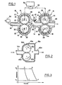
- Figure 1 schematically shows a constant displacement pump in the form of a gear pump motor (10) having successively, in the direction of flow, a compressor section (12), a combustion section (14) and a motor section (16).
- the compression section (12) comprises a casing (18) having inside two toothed wheels (20) which mesh, mounted on shafts (22), and arranged to rotate in the direction of the arrows.
- the drive section (16) has a housing (24) containing two gear wheels (26) which mesh, mounted on the shaft (28), and arranged to rotate in the direction indicated by the arrows.
- the combustion section (14) comprises a combustion chamber (30) having its inlet in communication with the outlet of the compressor (12) and its outlet in communication with the inlet of the drive section (16).
- a combustible gas for example a mixture of a vaporized fuel and air coming from a carburetor (34), enters through an inlet orifice (32) in the compression pump d 'where it is transported in elementary portions in the spaces (36) defined between two contiguous teeth and the inner surface of the housing (18).
- the elementary gas portions are discharged into the communication chamber bustion (30).
- the gas thus introduced into the combustion chamber can simply be air, in which case the fuel is injected directly into the combustion chamber (30) through an orifice (40). Combustion in the combustion chamber (30) is continuous under the conditions of temperature and pressure existing there.
- An ignition device such as a spark plug is installed to start the engine and, if necessary or desired, to maintain combustion during operation.
- the heated and pressurized products of combustion pass through the driving section (24) where they are transported in the spaces (44) between two adjacent teeth (46) and the inner surface of the housing (24).
- the gears (26) are thus moved in the direction of the arrows, and the gas escapes through an outlet orifice (48) to the outside or to another device capable of extracting energy from the gas.
- a certain part of the power obtained from the gears (26) rotated is transferred to the gears of the compressor in order to rotate them, for example by means of a mechanical rotation link (50).
- the value of K for this motor is greater than 1.0.
- An advantage of such an embodiment is that the rotation link (50) can be variable, so that the speed of the pump-compressor (12) relative to the pump-motor (16), is therefore the value of K , can be changed during engine operation to accommodate variations in engine load.
- thermodynamics there is a range of values for the volumetric ratio K defined above, dependent on the operating temperature (the temperature in the combustion chamber), which gives a capacity of output much greater than that envisaged in the preceding conceptions, where the value of K was necessarily bounded, in the interval from zero to one; values greater than unity were expressly excluded.
- the volumetric ratio K must have a value much greater than 1, typically of the order of five or more.
- K for a given motor as in FIG. 1, can be modified during operation, by means of a variable rotation link (50). Such an achievement would make it possible to choose K for the maximum power when the demand demands it and then to increase K to obtain an improved yield under conditions of least effort.
- variable transmission (50) can be controlled by a device (54) capable of measuring the load, so that the speed of the compressor will be increased or decreased relative to the speed of the engine according to a respective decrease or increase in the load, with a consequent increase or decrease of K.
- a device (54) capable of measuring the load, so that the speed of the compressor will be increased or decreased relative to the speed of the engine according to a respective decrease or increase in the load, with a consequent increase or decrease of K.
- Vc small elementary portion of air as it passes through the machine.
- the air portion is compressed to the pressure P 2 of the combustion chamber. Compression takes place quickly and therefore can be considered adiabatic.
- the portion of compressed air undergoes heating at constant pressure in the combustion chamber (2) until it reaches the temperature T 2 of the chamber.
- there is expansion of the portion during the heating phase and in fact it must expand until it reaches the volume Vm of an identical portion of air (heated and mixed with products of combustion) which is leaving the chamber to enter the motor pump (Cepi is a consequence of the constant regime that we have assumed).
- Figure 3 shows the diagram which represents the pressure and the volume of the portion during this process.
- the air enters the compressor at atmospheric pressure at point 1 of the slide. gram. It is compressed adiabatically from 1 to 2 when it is forced into the combustion chamber. Heating takes place at a constant pressure of 2 to 3, the gas expanding due to the addition of thermal energy produced by the combustion of the fuel. Finally, when the gas escapes from the machine, it expands adiabatically from 3 to 4, falling back to atmospheric pressure.
- thermodynamic cycle is that at constant pressure, familiar for example. in gas turbine applications.
- efficiency E of this cycle is equal to where T is the ratio of the specific heats of the air, roughly equal to 1.40.
- Equations (6) and (7) are new, having been obtained for the first time by the applicant, and they form the scientific basis of the invention described in this application.
- Figures 4 and 5 show that an attempt to operate a motor based on constant displacement pumps with a K value ⁇ 1.0, as taught in the prior art, would result in low efficiency and weak power.
- K the power starts to decrease if we go too far. Consequently, for a given motor, we would like to use it with K between fairly well defined limits. For example, for an engine designed for a temperature of 700 ° C, we would not take K greater than about five because of the reduction in power from this value; but it would be reasonable to take K around 4. Similarly, for an engine operating at 1000 ° C we would choose K below 7.5, and, for an engine at 1400'C, below 11.
- V m 50 cm 3 , which (for the gear pump) corresponds to a diameter of the gears of around 13 cm, for a thickness of 2.5 cm.
- V m 50 cm 3 and the same speed, these figures correspond to powers of 2.22 CV and 5.62 CV, respectively.
- the motor (10) may include other features unrelated to the quantity K considered above.
- the teeth (26a) of the gears in the driving part could be in contact with the casing (24a) only on an area close to the outlet of the combustion chamber thus facilitating the cooling of the driving section.
- Zone A of this part, downstream of the contact area between the teeth and the casing could contain a bath or jet of oil through which the teeth pass.
- the housing (24a) can be provided with fins or surrounded by a cooling bath. Cooling by forced air in the axial direction would be possible, especially with spoke gears.
- thicker or larger diameter gears can be used.
- the engine can be started by conventional methods. Starting would be considerably facilitated by means of a simple pipe with an exhaust member forming a decompressor, for example a simple by-pass valve, connected to the combustion chamber allowing the escape of a certain amount of air, thus reducing the pressure. internal during startup.
- a decompressor for example a simple by-pass valve
- the fuel can be introduced into the combustion chamber by various means, for example a carburetor or a nozzle (not shown) placed in the neck.
- the liquid fuels are supplied under high pressure in the chamber (for example around 5000 psi) to ensure good spraying.
- a suitable pump e.g. a small gear pump.
- the ignition can be obtained by an electric spark in the chamber (for example spark plug (42)). Gaseous fuels would be just as useful.
- the engine described above offers considerable advantages over other types of internal combustion engine. It combines the simplicity of the gas turbine with the superior characteristics of piston engines.
- Each of these engines has periods of very high pressure during its operation. As already indicated, in the engine described here, much higher temperatures than 700 ° C are workable, hence a higher yield than that of diesel and gasoline engines of common use.
- the engine described here can operate on a wide variety of fuels, including heavy oils. As the operating temperatures are far below those encountered during part of their cycle by diesel and petrol engines, the production of polluting gases is considerably reduced.
Landscapes
- Engineering & Computer Science (AREA)
- Chemical & Material Sciences (AREA)
- Combustion & Propulsion (AREA)
- Mechanical Engineering (AREA)
- General Engineering & Computer Science (AREA)
- Compressors, Vaccum Pumps And Other Relevant Systems (AREA)
- Output Control And Ontrol Of Special Type Engine (AREA)
Applications Claiming Priority (2)
| Application Number | Priority Date | Filing Date | Title |
|---|---|---|---|
| US86371386A | 1986-05-16 | 1986-05-16 | |
| US863713 | 1986-05-16 |
Publications (2)
| Publication Number | Publication Date |
|---|---|
| EP0246955A2 true EP0246955A2 (de) | 1987-11-25 |
| EP0246955A3 EP0246955A3 (de) | 1989-01-11 |
Family
ID=25341627
Family Applications (1)
| Application Number | Title | Priority Date | Filing Date |
|---|---|---|---|
| EP87401087A Withdrawn EP0246955A3 (de) | 1986-05-16 | 1987-05-14 | Brennkraftmaschine |
Country Status (1)
| Country | Link |
|---|---|
| EP (1) | EP0246955A3 (de) |
Cited By (4)
| Publication number | Priority date | Publication date | Assignee | Title |
|---|---|---|---|---|
| ES2154569A1 (es) * | 1998-10-14 | 2001-04-01 | Saiz Manuel Munoz | Motor rotativo. |
| WO2001063108A1 (en) * | 2000-02-24 | 2001-08-30 | Kjell Roar Kilen | Twin-shaft rotary engine |
| RU2205285C2 (ru) * | 2001-03-20 | 2003-05-27 | Нарижный Александр Афанасьевич | Двигатель внутреннего сгорания и устройство подготовки топливной смеси |
| CN108590771A (zh) * | 2018-04-18 | 2018-09-28 | 中国人民解放军海军工程大学 | 一种燃料电池系统高压比压气机及能量回收涡轮装置 |
Family Cites Families (3)
| Publication number | Priority date | Publication date | Assignee | Title |
|---|---|---|---|---|
| US2358815A (en) * | 1935-03-28 | 1944-09-26 | Jarvis C Marble | Compressor apparatus |
| JPS50102711A (de) * | 1974-01-25 | 1975-08-14 | ||
| US4228654A (en) * | 1978-12-07 | 1980-10-21 | Hill Craig C | Heat recuperative engine with improved recuperator |
-
1987
- 1987-05-14 EP EP87401087A patent/EP0246955A3/de not_active Withdrawn
Cited By (4)
| Publication number | Priority date | Publication date | Assignee | Title |
|---|---|---|---|---|
| ES2154569A1 (es) * | 1998-10-14 | 2001-04-01 | Saiz Manuel Munoz | Motor rotativo. |
| WO2001063108A1 (en) * | 2000-02-24 | 2001-08-30 | Kjell Roar Kilen | Twin-shaft rotary engine |
| RU2205285C2 (ru) * | 2001-03-20 | 2003-05-27 | Нарижный Александр Афанасьевич | Двигатель внутреннего сгорания и устройство подготовки топливной смеси |
| CN108590771A (zh) * | 2018-04-18 | 2018-09-28 | 中国人民解放军海军工程大学 | 一种燃料电池系统高压比压气机及能量回收涡轮装置 |
Also Published As
| Publication number | Publication date |
|---|---|
| EP0246955A3 (de) | 1989-01-11 |
Similar Documents
| Publication | Publication Date | Title |
|---|---|---|
| FR2748776A1 (fr) | Procede de moteur a combustion interne cyclique a chambre de combustion independante a volume constant | |
| EP0062043B1 (de) | Verfahren und maschine zur durchführung einer quasi-isothermischen zustandsänderung bei gaskompressions- oder expansionsvorgängen | |
| MC1412A1 (fr) | Moteur thermique rotatif,son procede de commande,et ensemble d'elements destines a former un tel moteur par transformation d'un moteur existant | |
| FR2779480A1 (fr) | Procede de fonctionnement et dispositif de moteur a injection d'air comprime additionnel fonctionnant en mono energie, ou en bi energie bi ou tri modes d'alimentation | |
| EP0034085B1 (de) | Gaserzeuger mit positiver Verdrängung | |
| FR2485087A1 (fr) | Moteur a combustion interne | |
| WO2003023206A1 (fr) | Turbine a gaz avec combustion intermittente | |
| EP0034958B1 (de) | Motor mit Drehkolben, die eine periodisch veränderliche Geschwindigkeit haben, und Antriebsmitteln | |
| EP1498590B1 (de) | Aufgeladene Viertakt-Brennkraftmaschine mit einer volumenändernden Abgasvorrichtung und Betriebsverfahren für eine solche Brennkraftmaschine | |
| FR2841598A1 (fr) | Appareil de commande pour un moteur a combustion interne et son procede de commande | |
| EP0246955A2 (de) | Brennkraftmaschine | |
| FR2478741A1 (fr) | Moteur a combustion interne parallele a soupape rotative et a equilibrage inherent | |
| FR2777943A1 (fr) | Moteur thermique a capsulismes differencies et apport de chaleur continu | |
| FR2668199A1 (fr) | Moteur d'automobile a combustion interne, de type a injection totale avec chauffage de l'air comprime par les gaz d'echappement. | |
| EP0024460A1 (de) | Verfahren für die Aufstellung rotierender Maschinen in mehreren neuen Anwendungen und Vorrichtungen für den Betrieb | |
| EP3259449A1 (de) | Scherenartige kompressions- und expansionsmaschine in einem wärmeenergierückgewinnungssystem | |
| FR2730274A1 (fr) | Moteur a pistons rotatifs et combustion externe | |
| EP1359309A1 (de) | Gasturbine mit einer Loben- und Röhren-Mischvorrichtung | |
| FR2690201A1 (fr) | Dispositif mécanique rotatif permettant la réalisation de compresseurs, de pompes ou de moteurs et moteurs selon ce dispositif. | |
| EP1167720B1 (de) | Isochore Brennkraftmaschine | |
| FR2944829A1 (fr) | Moteur rotatif a explosion equipe de pales coulissantes | |
| FR3033000B1 (fr) | Machine de compression et detente d'un fluide, ainsi que son utilisation dans un systeme de recuperation d'energie thermique | |
| FR2602825A1 (fr) | Moteur rotatif a combustion interne | |
| CA2141273A1 (fr) | Procede d'injections combinees de combustible avant et apres le point mort superieur du piston d'un moteur a combustion interne | |
| EP0886723A1 (de) | Brennkraftmaschine mit druckluftzündung und drehschieber |
Legal Events
| Date | Code | Title | Description |
|---|---|---|---|
| PUAI | Public reference made under article 153(3) epc to a published international application that has entered the european phase |
Free format text: ORIGINAL CODE: 0009012 |
|
| AK | Designated contracting states |
Kind code of ref document: A2 Designated state(s): CH DE FR GB IT LI |
|
| PUAL | Search report despatched |
Free format text: ORIGINAL CODE: 0009013 |
|
| AK | Designated contracting states |
Kind code of ref document: A3 Designated state(s): CH DE FR GB IT LI |
|
| STAA | Information on the status of an ep patent application or granted ep patent |
Free format text: STATUS: THE APPLICATION IS DEEMED TO BE WITHDRAWN |
|
| 18D | Application deemed to be withdrawn |
Effective date: 19890808 |