EP0246938B1 - Tastenfeld mit Strahlungsunterbrechung - Google Patents
Tastenfeld mit Strahlungsunterbrechung Download PDFInfo
- Publication number
- EP0246938B1 EP0246938B1 EP87400916A EP87400916A EP0246938B1 EP 0246938 B1 EP0246938 B1 EP 0246938B1 EP 87400916 A EP87400916 A EP 87400916A EP 87400916 A EP87400916 A EP 87400916A EP 0246938 B1 EP0246938 B1 EP 0246938B1
- Authority
- EP
- European Patent Office
- Prior art keywords
- keyboard
- radiation
- light
- key
- keys
- Prior art date
- Legal status (The legal status is an assumption and is not a legal conclusion. Google has not performed a legal analysis and makes no representation as to the accuracy of the status listed.)
- Expired - Lifetime
Links
- 230000005855 radiation Effects 0.000 title claims abstract description 51
- 239000011159 matrix material Substances 0.000 claims abstract description 7
- 239000000463 material Substances 0.000 claims description 6
- 238000007789 sealing Methods 0.000 claims description 2
- 239000012780 transparent material Substances 0.000 abstract description 9
- 238000011144 upstream manufacturing Methods 0.000 abstract description 3
- 230000005540 biological transmission Effects 0.000 description 5
- 239000000428 dust Substances 0.000 description 4
- 238000009434 installation Methods 0.000 description 4
- 238000004519 manufacturing process Methods 0.000 description 3
- 230000000994 depressogenic effect Effects 0.000 description 2
- 238000001514 detection method Methods 0.000 description 2
- 230000003287 optical effect Effects 0.000 description 2
- 239000013307 optical fiber Substances 0.000 description 2
- 230000000644 propagated effect Effects 0.000 description 2
- 230000035807 sensation Effects 0.000 description 2
- 241001482963 Thamnophis Species 0.000 description 1
- NIXOWILDQLNWCW-UHFFFAOYSA-N acrylic acid group Chemical group C(C=C)(=O)O NIXOWILDQLNWCW-UHFFFAOYSA-N 0.000 description 1
- 230000006978 adaptation Effects 0.000 description 1
- 229910000808 amorphous metal alloy Inorganic materials 0.000 description 1
- 230000000903 blocking effect Effects 0.000 description 1
- 229910052796 boron Inorganic materials 0.000 description 1
- 230000007547 defect Effects 0.000 description 1
- 230000008021 deposition Effects 0.000 description 1
- 238000010586 diagram Methods 0.000 description 1
- 229920001971 elastomer Polymers 0.000 description 1
- 239000000806 elastomer Substances 0.000 description 1
- 239000006263 elastomeric foam Substances 0.000 description 1
- 230000005670 electromagnetic radiation Effects 0.000 description 1
- 230000005284 excitation Effects 0.000 description 1
- 229920002457 flexible plastic Polymers 0.000 description 1
- 230000006870 function Effects 0.000 description 1
- 238000005286 illumination Methods 0.000 description 1
- 230000010365 information processing Effects 0.000 description 1
- 239000003550 marker Substances 0.000 description 1
- 238000000465 moulding Methods 0.000 description 1
- 238000005192 partition Methods 0.000 description 1
- 230000035515 penetration Effects 0.000 description 1
- 229920003023 plastic Polymers 0.000 description 1
- 230000000750 progressive effect Effects 0.000 description 1
- 230000001902 propagating effect Effects 0.000 description 1
- 239000007787 solid Substances 0.000 description 1
- 230000009466 transformation Effects 0.000 description 1
Images


Classifications
-
- H—ELECTRICITY
- H03—ELECTRONIC CIRCUITRY
- H03K—PULSE TECHNIQUE
- H03K17/00—Electronic switching or gating, i.e. not by contact-making and –breaking
- H03K17/94—Electronic switching or gating, i.e. not by contact-making and –breaking characterised by the way in which the control signals are generated
- H03K17/965—Switches controlled by moving an element forming part of the switch
- H03K17/968—Switches controlled by moving an element forming part of the switch using opto-electronic devices
- H03K17/969—Switches controlled by moving an element forming part of the switch using opto-electronic devices having a plurality of control members, e.g. keyboard
Definitions
- the present invention relates to a keyboard comprising a matrix of keys, a radiation emitter by column of keys, a radiation receiver by line of keys, means arranged at each crossing of a column and a line, for deflecting radiation from the corresponding transmitter to the corresponding receiver, means controlled by each key to interrupt the radiation from the corresponding transmitter, and means for controlling the transmitters sequentially and cyclically.
- Such a keyboard allows manual entry of alphanumeric data into a word processing machine, a computer, or a terminal connected to a telecommunications network, for example.
- each column includes a first light guide, made of transparent material with a greater index than that of the air, inside which the light emitted by the corresponding emitter is propagated, and each line includes a second light guide, made of the same material as the first guide, inside which propagates the light received by the corresponding receiver .
- Each means for deflecting the radiation from a transmitter to a receiver comprises, in the first guide, or emission guide, two reflecting surfaces for causing, out of the emission guide and in a direction parallel to that of the second guide, or reception guide, part of the light emitted, and, in the reception guide, a reflecting surface for bringing in the light exited from the emission guide.
- Each interruption means comprises an opaque flap which comes to be interposed between the transmission guide and the reception guide, to interrupt the light radiation.
- Such a keyboard has several drawbacks.
- the transparent material used for the guides not being perfect, the light propagates there with attenuation.
- the radiation from the transmitter undergoes three reflections.
- this radiation must pass through an air-transparent medium interface and then a transparent-air medium interface.
- each reflection or passage of the interface gives rise to losses of light energy.
- the portion of light emitted by a transmitter which is received by a receiver is relatively small. This reduces the operational safety of the keyboard and requires the use of powerful sources and sensitive sensors.
- the use and installation of relatively complex shape emission guides increase manufacturing costs.
- European application EP-A-0 151 022 also describes a matrix keyboard comprising a light emitter per column and a receiver per line and means for controlling the emitters sequentially and cyclically.
- this keyboard light propagates in the air, inside hollow and rectilinear channels corresponding to columns and rows.
- Such a keyboard therefore has none of the above drawbacks.
- the light propagating in a straight line, and the columns being substantially perpendicular to the lines, it is not possible to use, as in US Pat. No. 4,417,824, keys each controlling a single opaque flap. In fact, in the absence of means for deflecting the light radiation from the emitters to the receivers, no receiver never receives light from any emitter.
- keys are used which each control the installation, at the intersection of a column and a line, of means for deflecting the light radiation from the corresponding emitter to the corresponding receiver.
- These deflection means are, in this case, constituted by a reflecting surface inclined relative to the direction of propagation of the light in the column, for deflecting part of the light emitted by an angle of substantially 90 °, in the direction of the line.
- a totally reflecting surface controlled by the key to interpose on only part of the section of the propagation channel or a semi-reflective surface controlled by the key to interpose over the entire section of the propagation channel. In both cases, even if a key is pressed, it does not completely prevent the passage of light, which allows recognition of the keys pressed downstream, in the direction of propagation of the radiation, in the same column, or of those located upstream in the same line.
- a keyboard like the one just described if it does not have the defects inherent in keyboards using light guides made of transparent material with an index higher than that of air, has other drawbacks, however.
- each of the keys controlling the installation of a movable reflecting surface whose angle of inclination must remain strictly constant, is mechanically more complicated than a key which commands the installation of a flap opaque whose angle of inclination is not critical.
- pressing a key does not cancel the light downstream of this key, it does attenuation in relatively large proportions. This reduces the operational reliability of the keyboard, and therefore also results in the use of powerful sources and sensitive sensors.
- the present invention aims to overcome the above drawbacks.
- each means of interruption is in direct view of the corresponding transmitter, and each means of deflection is arranged, in the path of the beam of the corresponding transmitter, downstream of the associated interrupting means.
- the deflection means is arranged downstream of the operating position of the interrupting means.
- each line comprises means for guiding the radiation deflected by the deflection means.
- the guide means make it possible to guide the radiation so that the pressing of a key does not hinder the recognition of a key situated upstream in the same line.
- said radiation is radiation luminous
- the guide means comprise a strip of material transparent to said radiation
- each deflection means comprises a reflecting surface of said strip.
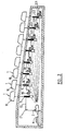
- a keyboard for manually entering data into an information processing machine, for example, comprises a matrix of keys 1, represented in dotted lines in FIG. 1.
- a radiation emitter in this case a light-emitting diode 2, arranged so that the keys of column 20 are on the path of the light beam which it emits.
- Each line 30 of the key matrix corresponds to a receiver of the emitted radiation, in this case a photodiode 3, arranged to be able to receive light radiation coming from each of the keys of line 30.
- each column 20 and each line 30 are arranged means 4, which will be described below, for deflecting part of the light emitted by the corresponding light-emitting diode 2 towards the corresponding photodiode 3.
- Each key controls a means of interrupting the light beam, in this case an opaque flap 5 which comes to interpose on the path of this beam.
- the examination of the output signals of the photodiodes 3 provides information on the keys 1 of the column of row j which are pressed. For example, if the photodiode of rank k delivers a zero output signal, it means that the key located at the intersection of the column of rank j and the row of rank k is pressed.
- an electronic circuit for example with a microprocessor, and comprising here printed plates 6 and 7, therefore delivers on a connector 61 an output signal corresponding at all times to the keys pressed, and performs the function known to those skilled in the art under the name "N key roll-over".
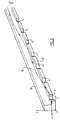
- a rectilinear hollow channel delimited by walls 21, here reflecting, corresponds to each column 20.
- Each channel 20 is arranged in the radiation axis of each light-emitting diode 2.
- the light-emitting diodes 2 are here with a narrow radiation diagram, as a first approximation contained in an angle of ⁇ 10 ° and of total radiated power of the order of 20 milliwatts for an excitation current of 100 milliamps at 20 degrees Celcius. Such diodes, emitting at a wavelength of 930 nanometers, are commonly available.
- a light radiation guide here a strip of transparent material with an index higher than that of air, corresponds to each line 30.
- Each strip 30 is arranged in the receiving axis of each photodiode 3.
- the photodiodes 3 are here PIN type.
- the bars 30 are produced here in a material of the acrylic type with an index substantially equal to 1.5, at the wavelength used.
- the channels 20 and the bars 30 here form an angle of the order of 76 °.
- the walls 21, here integral with the bottom of the keyboard housing have an upper edge 22 arranged to support the bars 30.
- the bars 30 are all identical and have a substantially L-shaped cross section. bars 30 are supported in recesses 221 of the upper edge 22 of each wall 21, of positions and shapes such that the surface corresponding to the lower part, located on the right, of the substantially vertical bar of the L of the cross section of each strip 30 is in direct view of the light-emitting diode 2.
- each wall 21 also includes recesses 222 which allow each flap 5 integral with the cap 10 of each button 1 to come into play on the path of the light beam between the light-emitting diode 2 and each strip 30. In position blocking, or interrupting, the radiation, each flap 5 is therefore in direct view of the light-emitting diode 2.
- the design of the recesses 221 and 222 of the upper edge 22 of the wall 21 is established by proceeding as follows.
- the spacing between the flaps 5 being imposed by the pitch between the keys 1, here close to 19 mm, the recess 222 for the flap 5 furthest from the light-emitting diode 2, hereinafter called the first flap, is provided to so that, in the depressed position, this flap 5 comes practically to touch the bottom of the keyboard case.
- a stroke of 4 mm of the flap 5 is sufficient, so as to control without a doubt the concealment or the illumination of an area with a height equal to 2 mm from the bar 30.
- the position of the recess 221 for the corresponding bar 30, or first bar 30, is therefore provided accordingly. Its shape is provided so that the direction of the substantially vertical bar of the L of the cross section of the first strip 30 has a direction substantially perpendicular to that of the light beam between the light-emitting diode 2 and this first strip 30.
- the recess 222 of the next flap 5, or second flap 5, is provided so that, in the depressed position, this second flap 5 does not come into play on the light beam between the light-emitting diode 2 and the first strip 30.
- the second flap 5 will therefore be further from the bottom of the housing than the first flap 5.
- the recess 221 of the second bar 30 is provided by following the same rules as above. Then, taking into account the inclination of the light beam between the light-emitting diode 2 and the second strip 30, relative to the light beam between this diode 2 and the first strip 30, the position of the second strip 30 is slightly tilted relative to the position of the first bar 30.
- the directions of the substantially vertical bars of the L of the straight sections of the bars 30 are not strictly perpendicular to the directions of light beams between the light-emitting diode 2 and these bars 30. This results from the fact that, taking into account the particular shape of the bars 30, which will be described below, an experimental adjustment of the position of these bars around from the position defined above, adjustment within the reach of those skilled in the art, makes it possible to optimize the optical transmission between the light-emitting diode 2 and each photodiode 3.
- the photodiodes 3 are protected from stray light by a screen 9 of matt black color absorbing the light which rises a few millimeters on the bars 30. This screen 9 also allows the precise positioning of the bars 30 in look at the photodiodes.
- the bars 30 also rest on a plate 35, with recesses similar to those of the walls 21, and disposed opposite the photodiodes 3.
- a plate of elastomeric foam 36 presses the bars 30 against the photodiodes 3.
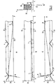
- each bar 30 is a cylinder of axis Oz which includes a body 32 and a flange 31 both of generally parallelepiped shape.
- the body 32 corresponds to a bar of the L of the cross section, bar which extends along an axis Ox
- the flange 31 corresponds to the other bar of this L, bar which extends along an Oy axis.
- the Ox, Oy, Oz coordinate system is a tri-rectangle coordinate system.
- the section of the body 32 of the bar is here a rectangle 4.5 mm high by 3 mm wide.
- the section of the rim 31 of the bar is here a square with a side of 1.5 mm.
- the length of a bar depends on the number of keys per line of the keyboard, and the pitch of these keys. It is here of the order of forty centimeters.
- rim 31 In the rim 31 are formed, at distances on the axis Oz, equal to the pitch between the keys, grooves with an axis substantially parallel to the axis Ox.
- the face 4 of these grooves intended to be on the side of the photodiode 2 is a face plane whose intersection with the yOz plane forms an angle from here 37 ° with the positive semi-axis Oz and an angle of 53 ° with the positive half-axis Oy, and whose intersection with the xOy plane here forms a 6 ° angle with the negative semi-axis Ox and an 84 ° angle with the negative half-axis Oy.
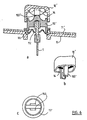
- control members between each cabochon 10 and the corresponding flap 5 form part of a single ply 11 of flexible plastic material of the elastomer type which covers the entire housing of the keyboard, without any opening towards the interior of the latter, which is thus made impermeable to the dust from the wear of the keys and to external pollution.
- the ply 11 comprises, at the location provided for each key 1, a substantially cylindrical key body 110, and, on the axis of the key body 110, a vertical finger 111, connected to the key body 110 by a bellows 112 , of the type known to corrugations.
- the height of the key body 110 and that of the finger 111 are variable and depend, as has been indicated, on the position of the line to which the corresponding key 1 belongs.
- the ply 11 is here supported by a rigid plate 13, having openings to allow the key bodies 110 to pass, the lower surface of which rests on the upper edge of the partitions 21.
- the cabochon 10 is provided internally with a rounded projection 101 which presses in the center of a spring leaf 14 embedded in a hard plastic ring 15 on which the inner edge of the cabochon 10 slides.
- This ring 15 rests on the body of the keys , it ensures the rigidity of the fingerboard.
- the spring 14 is a thin blade, preferably a blade of a ribbon of amorphous alloy of the Nickel-Iron-Chrome-Boron type, substantially 30 microns thick, cut chemically or by stamping to form a band of smaller width in its central part only at its ends, as shown in Figure 5 c .
- the ends of the blade 14 are anchored in the ring so that the blade 14 forms an arc of a circle, with an arrow of approximately 2 mm.
- the blade 14 deforms along the dotted line, ensuring a significant tactile sensation which prevents partial penetration or involuntary repetition.
- the protrusion 101 of the cap 10 is extended on two sides by cheeks 102 which fit into the upper part of the finger 111.
- the flap 5, of black color is here embedded in the lower part of the finger 111. It can have here four different shapes 5 a , 5 b , 5 c and 5 d , illustrated in FIG. 5 d , to adapt to the particular configuration of the cabochons 10 on the keyboard, while retaining strictly rectilinear columns 20 in the lower part of the case.
- the light radiation enters the corresponding bar 30. Its path is shown in FIGS. 3 and 4, materialized by the light ray bearing the reference 8. As can be seen in FIG. 4, because the angle between the bar 30 and the column 20 is here 76 °, the ray 8 arrives on the xOz plane under an incidence here of the order of 14 °. As the bar 30 is arranged so that the lower part of the body 32, located opposite the rim 31, is illuminated, the ray 8, inclined at 10 ° on the axis Oy after refraction by the air-material input interface transparent of the bar 30, strikes the surface 4 on which it is reflected. Given the position of the latter, the ray 8 is reflected in a direction close to that of the axis Oz. As the photodiode 2 is arranged in the direction of the axis Oz, it can therefore be said that the surface 4 constitutes a means of deflection of the light radiation from the light-emitting diode 2 towards the photodiode 3.
- the orientation of the surface 4 is such that the light ray 8 is reflected in a direction whose projection on the xOz plane is slightly inclined on the Oz axis, so as to also go towards the crescents.
- the radius after a first total reflection on the wall merged with the xOz plane, remains trapped in the body 32 over a fairly long distance. Indeed, it must undergo here about seven total reflections on the walls parallel to the plane xOz of the body 32 before being totally reflected on the upper wall, parallel to the plane yOz of the body 32, wall which returns it towards the lower part of the body 32 , which he reaches after about seven other reflections.
- the spoke 8 can return, during its propagation in the bar 30, on the rim 31 only after about 35 steps of keys.
- the orientation of the reflecting surface 4 is therefore such that, over the length of the strip 30, the propagation of the light ray 8 takes place in the body 32 of the bar 30, and not in the rim 31.
- the structure of the rim 31 is much more complex, taking into account the notches which are made there periodically to create reflective surfaces 4. These irregularities would be at the origin of light leaks if it were propagated there.
- the shape of the bar 30 is particularly judicious here.
- the bar 30 includes both means for deflecting the radiation, namely the surface 4, and guide means, namely the body 32. This makes it possible to obtain a deflection and guidance of the radiation with a minimum number of interfaces between the air and the transparent material.
- the arrangement of the bar 30 and the arrangement of the surface 4 are such that the deflection means distributed periodically along the bar 30, have no unfavorable influence on the propagation of light in the body 32 of the bar 30.
- the sealing of the housing avoids the deposition of dust on the input interface in the strip, and on the output interface, here flat for a good adaptation to the photodiode 2.
- Figures 6 show a first alternative embodiment of the keys 1.
- the elements identical to those of Figure 5 have the same reference.
- the ply 11 ′ does not include a touch body.
- the leaf spring 14 is mounted in the cap 10 ′, which also includes two internal sliding tabs 102 ′.
- the 15 ′ ring is a solid ring provided two openings 150 for guiding the sliding tabs 102 ′.
- the variant of FIG. 6 makes it possible to have a longer leaf spring 14, a wider bellows 112, and better vertical guidance of the button.
- FIGS. 7 show a second alternative embodiment of the keys 1.
- each key body 110 ⁇ is integral with the upper rigid plate 13 ⁇ of the keyboard. All the 110 ⁇ key bodies are thus obtained simultaneously during the molding of the plate 13 ⁇ .
- the cabochon 10 ⁇ slides outside the touch body 110 ⁇ , and consequently, any dust due to wear will fall outside the body 110 ⁇ and will not disturb the transmission of light inside of the keyboard, which makes it possible not to use a flexible ply like the plies 11 and 11 'of FIGS. 5 and 6.
- the spring 14 ⁇ is here a simple ribbon snake, from 1 to 3 mm wide, inserted in the key body 110 ⁇ , in abutment against the plate 13 ⁇ .
- the spring 14 ⁇ is pinched or glued at its ends.
- a rounded projection 101 ⁇ bears against the spring 14uyer.
- the profile of the projection 101 ⁇ is adjusted to obtain the desired tactile sensation when the key is pressed.
- the rod 51 of the flap 5 is fixed, for example by elastic straddling, to the projection 101 ⁇ .
- each bar 30 ′ is always substantially in the form of a cylinder, of cross section substantially in the form of L, with a body 32 ′ and a flange 31 ′ comparable to those of the bar 30 in FIG. 3.
- the flange 31 ' extends vertically, here from the side of the body 32 ′ furthest from the light-emitting diodes 2.
- Notches are formed in the rim 31 ′ to provide reflective surfaces 4 ′, inclined so that the reflected radiation remains guided inside the body 32 ′, after total reflection at 74 , on the vertical face of the body 32 ′ furthest from the light-emitting diodes 2.
- This variant is particularly well suited to the production of flat keyboards, and in which columns and bars are perpendicular.
- Figure 9 shows a second alternative embodiment of the bars.
- each bar 30 ⁇ intended to be arranged like the bar 30 is provided with a body 32 ⁇ of trapezoidal section, the two substantially vertical faces of the body 32 ⁇ no longer being parallel, but moving towards the top, at an angle ⁇ of a few degrees. In this way, the guided radiation remains more spatially concentrated, which presides over better detection.
- the arrangement of the keys which can be shifted from one row to the next by a multiple of a quarter of a step between keys, can be arbitrary and in particular conform to the standard alphanumeric typewriters, or even correspond to a regular layout for form a square or rectangle.
- light-emitting diodes can be replaced by laser diodes, and photodiodes by phototransistors, or by transmitters and receivers of other types of electromagnetic radiation or ultrasonic radiation.
- the keyboard can also be strictly optical by replacing the light-emitting diodes by arrivals of optical fibers having a numerical opening of 0.3, for example, and the PIN photodiodes by a termination of the strips connecting by a cone, of angle at the top equal to substantially 8 ° and 1 cm high, to an optical fiber having a digital aperture of 0.55, for example.
- the invention can also be used for a keyboard without keys where the operator's finger interrupts the path of the light, thus replacing the shutters which have been described.
- the invention can also be used for the detection and counting of any objects passing through hollow passages replacing the keys, or to constitute a panel with electronic output, using mechanical memory keys or marker objects placed in boxes in place of the keys, or, more generally, for any light transfer device implementing a strip similar to those which have been described.
Landscapes
- Input From Keyboards Or The Like (AREA)
- Push-Button Switches (AREA)
- Electronic Switches (AREA)
- Telephone Set Structure (AREA)
Claims (11)
Priority Applications (1)
| Application Number | Priority Date | Filing Date | Title |
|---|---|---|---|
| AT87400916T ATE67052T1 (de) | 1986-04-22 | 1987-04-21 | Tastenfeld mit strahlungsunterbrechung. |
Applications Claiming Priority (2)
| Application Number | Priority Date | Filing Date | Title |
|---|---|---|---|
| FR8605774A FR2597683B1 (fr) | 1986-04-22 | 1986-04-22 | Clavier a interrruption de rayonnement. |
| FR8605774 | 1986-04-22 |
Publications (2)
| Publication Number | Publication Date |
|---|---|
| EP0246938A1 EP0246938A1 (de) | 1987-11-25 |
| EP0246938B1 true EP0246938B1 (de) | 1991-09-04 |
Family
ID=9334471
Family Applications (1)
| Application Number | Title | Priority Date | Filing Date |
|---|---|---|---|
| EP87400916A Expired - Lifetime EP0246938B1 (de) | 1986-04-22 | 1987-04-21 | Tastenfeld mit Strahlungsunterbrechung |
Country Status (9)
| Country | Link |
|---|---|
| US (1) | US4860008A (de) |
| EP (1) | EP0246938B1 (de) |
| JP (1) | JPS6380420A (de) |
| AT (1) | ATE67052T1 (de) |
| CA (1) | CA1266313A (de) |
| DE (1) | DE3772624D1 (de) |
| ES (1) | ES2026556T3 (de) |
| FR (1) | FR2597683B1 (de) |
| GR (1) | GR3003271T3 (de) |
Cited By (1)
| Publication number | Priority date | Publication date | Assignee | Title |
|---|---|---|---|---|
| US12307021B2 (en) | 2023-10-31 | 2025-05-20 | Dell Products Lp | System and method for a quiet keyboard with optical matrix key positioning |
Families Citing this family (9)
| Publication number | Priority date | Publication date | Assignee | Title |
|---|---|---|---|---|
| SE460821B (sv) * | 1988-03-30 | 1989-11-20 | Electrolux Mecatronik Ab | Elektronisk tryckknappsstroemstaellare |
| GB9119092D0 (en) * | 1991-09-06 | 1991-10-23 | Sarnoff David Res Center | Optomechanical keyboard |
| US5563127A (en) * | 1993-03-24 | 1996-10-08 | The Dupont Merck Pharmaceutical Company | Boronic acid and ester inhibitors of thrombin |
| US8096714B2 (en) | 2006-10-31 | 2012-01-17 | Advantage Technology And Innovations, Inc. | Stenographic keyboard device providing extended set of keys and method for electronically adjusting key depth sensitivity |
| US7572078B2 (en) * | 2004-03-12 | 2009-08-11 | Advantage Technology & Innovations, Inc. | Electronic key depth sensing device and method for interpreting keystroke levels of the device |
| KR20070054299A (ko) * | 2005-11-23 | 2007-05-29 | 화남전자 주식회사 | 백라이트 기능을 가진 키보드 |
| CN105042404B (zh) * | 2015-05-28 | 2016-03-30 | 苏州达方电子有限公司 | 背光模组 |
| DE202019005869U1 (de) * | 2018-12-13 | 2022-11-18 | Razer (Asia-Pacific) Pte. Ltd. | Analoge Eingabe-Vorrichtung, Rechensystem und Computer-Analoge-Eingabe-Vorrichtung |
| CN111312547B (zh) * | 2019-06-18 | 2023-08-04 | 光宝电子(广州)有限公司 | 按键模块、应用其的键盘及电子装置 |
Citations (1)
| Publication number | Priority date | Publication date | Assignee | Title |
|---|---|---|---|---|
| US4417824A (en) * | 1982-03-29 | 1983-11-29 | International Business Machines Corporation | Optical keyboard with common light transmission members |
Family Cites Families (12)
| Publication number | Priority date | Publication date | Assignee | Title |
|---|---|---|---|---|
| US3603982A (en) * | 1969-05-02 | 1971-09-07 | Ncr Co | Data entry means |
| US3767022A (en) * | 1970-04-24 | 1973-10-23 | Singer Co | Return spring key stem boot |
| US3648050A (en) * | 1970-08-06 | 1972-03-07 | Tuh Kai Koo | Optoelectronic data entry means having plurality of control means to direct part of radiation in channel from radiation source to output channel |
| US3856127A (en) * | 1972-11-24 | 1974-12-24 | U Halfon | Photo-optical keyboard |
| US4384633A (en) * | 1981-03-23 | 1983-05-24 | Scm Corporation | Perforated acoustic transport member |
| FR2518864B1 (fr) * | 1981-12-23 | 1985-03-01 | Tech Electro Cie Indle | Clavier a touches en relief |
| US4480182A (en) * | 1982-03-16 | 1984-10-30 | Burroughs Corporation | Single plane optical membrane switch and keyboard |
| US4593191A (en) * | 1982-12-29 | 1986-06-03 | At&T Bell Laboratories | Pressure and optical sensitive device with deformable protrusions |
| FR2548394B1 (fr) * | 1983-06-29 | 1988-07-29 | Renault | Dispositif de commande opto-electronique |
| US4641026A (en) * | 1984-02-02 | 1987-02-03 | Texas Instruments Incorporated | Optically activated keyboard for digital system |
| WO1986001954A1 (fr) * | 1984-09-07 | 1986-03-27 | Alain Souloumiac | Clavier optique |
| US4912092A (en) * | 1986-03-27 | 1990-03-27 | The Regents Of The University Of California | Methods for increasing extracellular adenosine and for stabilizing mast cells |
-
1986
- 1986-04-22 FR FR8605774A patent/FR2597683B1/fr not_active Expired - Lifetime
-
1987
- 1987-04-20 US US07/039,948 patent/US4860008A/en not_active Expired - Fee Related
- 1987-04-21 ES ES198787400916T patent/ES2026556T3/es not_active Expired - Lifetime
- 1987-04-21 AT AT87400916T patent/ATE67052T1/de not_active IP Right Cessation
- 1987-04-21 DE DE8787400916T patent/DE3772624D1/de not_active Expired - Lifetime
- 1987-04-21 EP EP87400916A patent/EP0246938B1/de not_active Expired - Lifetime
- 1987-04-22 CA CA000535261A patent/CA1266313A/fr not_active Expired - Lifetime
- 1987-04-22 JP JP62099625A patent/JPS6380420A/ja active Pending
-
1991
- 1991-12-04 GR GR91401900T patent/GR3003271T3/el unknown
Patent Citations (1)
| Publication number | Priority date | Publication date | Assignee | Title |
|---|---|---|---|---|
| US4417824A (en) * | 1982-03-29 | 1983-11-29 | International Business Machines Corporation | Optical keyboard with common light transmission members |
Cited By (1)
| Publication number | Priority date | Publication date | Assignee | Title |
|---|---|---|---|---|
| US12307021B2 (en) | 2023-10-31 | 2025-05-20 | Dell Products Lp | System and method for a quiet keyboard with optical matrix key positioning |
Also Published As
| Publication number | Publication date |
|---|---|
| CA1266313A (fr) | 1990-02-27 |
| ES2026556T3 (es) | 1992-05-01 |
| EP0246938A1 (de) | 1987-11-25 |
| GR3003271T3 (en) | 1993-02-17 |
| US4860008A (en) | 1989-08-22 |
| JPS6380420A (ja) | 1988-04-11 |
| DE3772624D1 (de) | 1991-10-10 |
| FR2597683B1 (fr) | 1992-07-31 |
| FR2597683A1 (fr) | 1987-10-23 |
| ATE67052T1 (de) | 1991-09-15 |
Similar Documents
| Publication | Publication Date | Title |
|---|---|---|
| EP0246938B1 (de) | Tastenfeld mit Strahlungsunterbrechung | |
| EP0025097B1 (de) | Optischer Umschalter | |
| KR102425304B1 (ko) | 필드 내에서 거리 정보를 수집하기 위한 광학 시스템 | |
| US7995039B2 (en) | Touch pad system | |
| EP0258363B1 (de) | Massnahmen zur verbesserung von optischen tastenfeldern mit abtastung | |
| EP0115765B1 (de) | Drehschalter für optische Wellenführungsschaltung | |
| FR2570511A1 (fr) | Unite de circuit conduisant la lumiere | |
| FR2716742A1 (fr) | Appareil de lecture de surface inégale. | |
| EP1479338B1 (de) | Tragbares Gerät zur Erfassung einer physiologischen Messgrösse mit einem Gerät zur Beleuchtung der Oberfläche von organischem Gewebe | |
| FR2611263A1 (fr) | Dispositif pour mesurer des dimensions | |
| AU2007216782A1 (en) | Optical elements for waveguide-based optical touch input devices | |
| EP2960642A1 (de) | Optische kammer für gaserfassungsvorrichtung | |
| FR3070635B1 (fr) | Palette tactile a effet optique sur volant de conduite pour detection de doigt | |
| JP3849570B2 (ja) | 動作検出用部品 | |
| WO1987005759A1 (fr) | Ameliorations apportees aux claviers optiques a miroirs | |
| EP0004520A1 (de) | Tastatur mit einer aus Lichtteilern aufgebauten Matrix | |
| EP0397539A1 (de) | Berührungsempfindliche Anzeige mit geleiteten elastischen Wellen und oszillierender Schleife | |
| EP0096615B1 (de) | Optischer Schalter | |
| WO1986001954A1 (fr) | Clavier optique | |
| FR3025913A1 (fr) | Dispositif de lecture de codes-barres et machine pour l'analyse automatise d'un echantillon comprenant un tel dispositif | |
| EP3525015B1 (de) | Optisches monoblockelement mit diaphragma | |
| FR2518864A1 (fr) | Clavier a touches en relief | |
| US5981938A (en) | Opto-electronic device | |
| EP0497694A1 (de) | Optische Tastaturmatrix | |
| FR2595022A1 (fr) | Clavier optique |
Legal Events
| Date | Code | Title | Description |
|---|---|---|---|
| PUAI | Public reference made under article 153(3) epc to a published international application that has entered the european phase |
Free format text: ORIGINAL CODE: 0009012 |
|
| AK | Designated contracting states |
Kind code of ref document: A1 Designated state(s): AT BE CH DE ES FR GB GR IT LI LU NL SE |
|
| 17P | Request for examination filed |
Effective date: 19880511 |
|
| 17Q | First examination report despatched |
Effective date: 19891018 |
|
| RAP3 | Party data changed (applicant data changed or rights of an application transferred) |
Owner name: BATTAREL, CLAUDE |
|
| GRAA | (expected) grant |
Free format text: ORIGINAL CODE: 0009210 |
|
| AK | Designated contracting states |
Kind code of ref document: B1 Designated state(s): AT BE CH DE ES FR GB GR IT LI LU NL SE |
|
| REF | Corresponds to: |
Ref document number: 67052 Country of ref document: AT Date of ref document: 19910915 Kind code of ref document: T |
|
| 111L | Licence recorded |
Free format text: 0100 DATA CONVERSION TECHNOLOGIES * 0101 APR-COMPOSANTS |
|
| REF | Corresponds to: |
Ref document number: 3772624 Country of ref document: DE Date of ref document: 19911010 |
|
| REG | Reference to a national code |
Ref country code: CH Ref legal event code: PLI Owner name: DATA CONVERSION TECHNOLOGIES |
|
| ITF | It: translation for a ep patent filed | ||
| GBT | Gb: translation of ep patent filed (gb section 77(6)(a)/1977) | ||
| REG | Reference to a national code |
Ref country code: ES Ref legal event code: FG2A Ref document number: 2026556 Country of ref document: ES Kind code of ref document: T3 |
|
| PLBE | No opposition filed within time limit |
Free format text: ORIGINAL CODE: 0009261 |
|
| STAA | Information on the status of an ep patent application or granted ep patent |
Free format text: STATUS: NO OPPOSITION FILED WITHIN TIME LIMIT |
|
| 26N | No opposition filed | ||
| REG | Reference to a national code |
Ref country code: GR Ref legal event code: FG4A Free format text: 3003271 |
|
| EPTA | Lu: last paid annual fee | ||
| EAL | Se: european patent in force in sweden |
Ref document number: 87400916.0 |
|
| PGFP | Annual fee paid to national office [announced via postgrant information from national office to epo] |
Ref country code: SE Payment date: 19980415 Year of fee payment: 12 |
|
| PGFP | Annual fee paid to national office [announced via postgrant information from national office to epo] |
Ref country code: GB Payment date: 19980420 Year of fee payment: 12 |
|
| PGFP | Annual fee paid to national office [announced via postgrant information from national office to epo] |
Ref country code: FR Payment date: 19980424 Year of fee payment: 12 Ref country code: AT Payment date: 19980424 Year of fee payment: 12 |
|
| PGFP | Annual fee paid to national office [announced via postgrant information from national office to epo] |
Ref country code: ES Payment date: 19980427 Year of fee payment: 12 |
|
| PGFP | Annual fee paid to national office [announced via postgrant information from national office to epo] |
Ref country code: NL Payment date: 19980430 Year of fee payment: 12 Ref country code: GR Payment date: 19980430 Year of fee payment: 12 |
|
| PGFP | Annual fee paid to national office [announced via postgrant information from national office to epo] |
Ref country code: DE Payment date: 19980519 Year of fee payment: 12 |
|
| PGFP | Annual fee paid to national office [announced via postgrant information from national office to epo] |
Ref country code: CH Payment date: 19980520 Year of fee payment: 12 |
|
| PGFP | Annual fee paid to national office [announced via postgrant information from national office to epo] |
Ref country code: LU Payment date: 19980522 Year of fee payment: 12 |
|
| PGFP | Annual fee paid to national office [announced via postgrant information from national office to epo] |
Ref country code: BE Payment date: 19980615 Year of fee payment: 12 |
|
| PG25 | Lapsed in a contracting state [announced via postgrant information from national office to epo] |
Ref country code: LU Free format text: LAPSE BECAUSE OF NON-PAYMENT OF DUE FEES Effective date: 19990421 Ref country code: GB Free format text: LAPSE BECAUSE OF NON-PAYMENT OF DUE FEES Effective date: 19990421 Ref country code: AT Free format text: LAPSE BECAUSE OF NON-PAYMENT OF DUE FEES Effective date: 19990421 |
|
| PG25 | Lapsed in a contracting state [announced via postgrant information from national office to epo] |
Ref country code: SE Free format text: LAPSE BECAUSE OF NON-PAYMENT OF DUE FEES Effective date: 19990422 Ref country code: ES Free format text: LAPSE BECAUSE OF EXPIRATION OF PROTECTION Effective date: 19990422 |
|
| PG25 | Lapsed in a contracting state [announced via postgrant information from national office to epo] |
Ref country code: LI Free format text: LAPSE BECAUSE OF NON-PAYMENT OF DUE FEES Effective date: 19990430 Ref country code: GR Free format text: LAPSE BECAUSE OF NON-PAYMENT OF DUE FEES Effective date: 19990430 Ref country code: CH Free format text: LAPSE BECAUSE OF NON-PAYMENT OF DUE FEES Effective date: 19990430 Ref country code: BE Free format text: LAPSE BECAUSE OF NON-PAYMENT OF DUE FEES Effective date: 19990430 |
|
| BERE | Be: lapsed |
Owner name: BATTAREL CLAUDE Effective date: 19990430 |
|
| PG25 | Lapsed in a contracting state [announced via postgrant information from national office to epo] |
Ref country code: NL Free format text: LAPSE BECAUSE OF NON-PAYMENT OF DUE FEES Effective date: 19991101 |
|
| GBPC | Gb: european patent ceased through non-payment of renewal fee |
Effective date: 19990421 |
|
| REG | Reference to a national code |
Ref country code: CH Ref legal event code: PL |
|
| PG25 | Lapsed in a contracting state [announced via postgrant information from national office to epo] |
Ref country code: FR Free format text: LAPSE BECAUSE OF NON-PAYMENT OF DUE FEES Effective date: 19991231 |
|
| NLV4 | Nl: lapsed or anulled due to non-payment of the annual fee |
Effective date: 19991101 |
|
| EUG | Se: european patent has lapsed |
Ref document number: 87400916.0 |
|
| REG | Reference to a national code |
Ref country code: FR Ref legal event code: ST |
|
| PG25 | Lapsed in a contracting state [announced via postgrant information from national office to epo] |
Ref country code: DE Free format text: LAPSE BECAUSE OF NON-PAYMENT OF DUE FEES Effective date: 20000201 |
|
| REG | Reference to a national code |
Ref country code: ES Ref legal event code: FD2A Effective date: 20010601 |
|
| PG25 | Lapsed in a contracting state [announced via postgrant information from national office to epo] |
Ref country code: IT Free format text: LAPSE BECAUSE OF NON-PAYMENT OF DUE FEES;WARNING: LAPSES OF ITALIAN PATENTS WITH EFFECTIVE DATE BEFORE 2007 MAY HAVE OCCURRED AT ANY TIME BEFORE 2007. THE CORRECT EFFECTIVE DATE MAY BE DIFFERENT FROM THE ONE RECORDED. Effective date: 20050421 |