EP0246884B1 - Antriebseinheit für ein Fahrzeug mit Vierradantrieb - Google Patents
Antriebseinheit für ein Fahrzeug mit Vierradantrieb Download PDFInfo
- Publication number
- EP0246884B1 EP0246884B1 EP87304496A EP87304496A EP0246884B1 EP 0246884 B1 EP0246884 B1 EP 0246884B1 EP 87304496 A EP87304496 A EP 87304496A EP 87304496 A EP87304496 A EP 87304496A EP 0246884 B1 EP0246884 B1 EP 0246884B1
- Authority
- EP
- European Patent Office
- Prior art keywords
- clutch
- differential
- automatic transmission
- power transmission
- wheel drive
- Prior art date
- Legal status (The legal status is an assumption and is not a legal conclusion. Google has not performed a legal analysis and makes no representation as to the accuracy of the status listed.)
- Expired - Lifetime
Links
- 230000005540 biological transmission Effects 0.000 title claims abstract description 25
- 241000282472 Canis lupus familiaris Species 0.000 description 3
- 230000001276 controlling effect Effects 0.000 description 3
- 230000000452 restraining effect Effects 0.000 description 2
- 230000001133 acceleration Effects 0.000 description 1
- 230000001419 dependent effect Effects 0.000 description 1
- 239000003607 modifier Substances 0.000 description 1
- 230000001105 regulatory effect Effects 0.000 description 1
Images


Classifications
-
- B—PERFORMING OPERATIONS; TRANSPORTING
- B60—VEHICLES IN GENERAL
- B60K—ARRANGEMENT OR MOUNTING OF PROPULSION UNITS OR OF TRANSMISSIONS IN VEHICLES; ARRANGEMENT OR MOUNTING OF PLURAL DIVERSE PRIME-MOVERS IN VEHICLES; AUXILIARY DRIVES FOR VEHICLES; INSTRUMENTATION OR DASHBOARDS FOR VEHICLES; ARRANGEMENTS IN CONNECTION WITH COOLING, AIR INTAKE, GAS EXHAUST OR FUEL SUPPLY OF PROPULSION UNITS IN VEHICLES
- B60K17/00—Arrangement or mounting of transmissions in vehicles
- B60K17/34—Arrangement or mounting of transmissions in vehicles for driving both front and rear wheels, e.g. four wheel drive vehicles
- B60K17/344—Arrangement or mounting of transmissions in vehicles for driving both front and rear wheels, e.g. four wheel drive vehicles having a transfer gear
- B60K17/346—Arrangement or mounting of transmissions in vehicles for driving both front and rear wheels, e.g. four wheel drive vehicles having a transfer gear the transfer gear being a differential gear
- B60K17/3462—Arrangement or mounting of transmissions in vehicles for driving both front and rear wheels, e.g. four wheel drive vehicles having a transfer gear the transfer gear being a differential gear with means for changing distribution of torque between front and rear wheels
-
- B—PERFORMING OPERATIONS; TRANSPORTING
- B60—VEHICLES IN GENERAL
- B60K—ARRANGEMENT OR MOUNTING OF PROPULSION UNITS OR OF TRANSMISSIONS IN VEHICLES; ARRANGEMENT OR MOUNTING OF PLURAL DIVERSE PRIME-MOVERS IN VEHICLES; AUXILIARY DRIVES FOR VEHICLES; INSTRUMENTATION OR DASHBOARDS FOR VEHICLES; ARRANGEMENTS IN CONNECTION WITH COOLING, AIR INTAKE, GAS EXHAUST OR FUEL SUPPLY OF PROPULSION UNITS IN VEHICLES
- B60K23/00—Arrangement or mounting of control devices for vehicle transmissions, or parts thereof, not otherwise provided for
- B60K23/08—Arrangement or mounting of control devices for vehicle transmissions, or parts thereof, not otherwise provided for for changing number of driven wheels, for switching from driving one axle to driving two or more axles
- B60K23/0808—Arrangement or mounting of control devices for vehicle transmissions, or parts thereof, not otherwise provided for for changing number of driven wheels, for switching from driving one axle to driving two or more axles for varying torque distribution between driven axles, e.g. by transfer clutch
Definitions
- the present invention relates to a system for transmitting the power of an engine to the front and the rear wheels of a four wheel drive vehicle having an automatic transmission.
- a full time four-wheel drive vehicle having a central differential is well known.
- a differential lock system is provided for preventing front or rear wheels from skidding.
- a dog clutch device operated by a pneumatic actuator is widely used. However, if the actuator is operated when the vehicle is stationary or when cornering, the dog clutch does not engage unless the actuator is operated at the time when corresponding dogs coincide with each other. Further, it frequently happens that the clutch engages after some delay under particular driving conditions.
- An object of the present invention is to provide such a four-wheel drive system but where the clutch capacity can be quickly varied to control the distribution of the power to the driving wheels.
- a power transmission system for a four-wheel drive vehicle having an engine connected to an automatic transmission comprises a differential operatively connected to an output member of the automatic transmission and having first and second side gears, a first drive train connected to transmit rotation of the first side gear to a first drive shaft, a second drive train connected to transmit rotation of the second side gear to a second side shaft, a hydraulically operable clutch provided between the first and second side gears and arranged, when operated to connect the two side gears for locking the differential, and a hydraulic control circuit for controlling the supply of oil to the clutch characterised in that the clutch is controlled by pressure of said oil in dependency on the degree of opening of a throttle valve of the engine.
- the hydraulic control circuit is arranged to apply line pressure of the automatic transmission to the clutch and furthermore the control circuit has a solenoid operated control valve for controlling the supply of the oil.
- an automatic transmission 1 for a motor vehicle comprises a torque converter 3 for transmitting the power of an engine 2 to the transmission, a planetary gear device 4, a reverse clutch 5, a forward clutch 6, and a low and reverse brake 7, as is well known.
- a central differential 8 is disposed adjacent a rear portion of the transmission 1.
- the central differential 8 comprises a pinion shaft 10 connected to a ring gear 11 of the planetary gear device 4, a pair of pinions 12 mounted on the pinion shaft 10, a pair of side gears 13 and 14 engaged with the pinions 12, and a differential housing 15.
- a reduction gear 16 integral with the side gear 13 is secured to the housing 15 by a bolt 17 and engages with a reduction driven gear 18.
- the gear 18 is secured to a front wheel drive 20.
- the rotation of the front wheel drive shaft 20 is transmitted to the front wheels of the vehicle through a pinion 21 and a front differential 22.
- the side gear 14 is operatively connected to a rear drive shaft 23.
- the central differential 8 is operatively connected to a hydraulic multi-disc friction clutch 24 which serves as a differential lock device.
- the clutch 24 comprises an inner drum 25 having a plurality of upstanding discs and secured to a boss of the differential housing 15, an outer drum 26 having a plurality of inwardly extending discs and secured to a shaft of the side gear 14 by splines, a piston 27 slidably mounted in the outer drum 26, and a spring 28 provided between the piston 27 and a retainer 30 secured to the outer drum so as to urge the piston in the clutch disengage direction.
- An oil chamber 31 between the outer drum and the piston is supplied with oil from a hydraulic control system 32 of the automatic transmission, as described hereinafter.
- the hydraulic control system has an oil pressure regulator valve 33 for regulating the line pressure of oil supplied from an oil pump 42, a manual valve 34 for selecting the driving ranges, a 1-2 shift valve 35, a 2-3 shift valve 36, a pressure modifier valve 37, a downshift valve 38, a vacuum throttle valve 39, a throttle back-up valve 40, and a second lock valve 41. Since this hydraulic control circuit is well known, more detailed description will not be necessary.
- a hydraulic control circuit 60 for controlling the central differential.
- the control circuit 60 comprises a solenoid operated control valve 43 having an inlet port 44 communicated with a line pressure passage 45 of the hydraulic control system 32 through a passage 46 so as to be supplied with line pressure, an outlet port 47 communicated with the chamber 31 of the clutch 24 through a passage 48, a drain port 50, a spool 51, a solenoid 52 for shifting the spool 51, and a spring 53 for biasing the spool 51 to a drain position.
- the solenoid 52 is connected to a battery 54 of the vehicle through a switch 55 attached to a selector lever 56 for operating the manual valve 34 of the automatic transmission and an ignition switch 57.
- the central differential 8 When the switch 55 is opened, the central differential 8 operates to properly distribute the power of the engine to the front and rear wheels in accordance with the driving conditions.
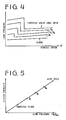
- the central differential 8 When the switch 55 is closed, the central differential 8 is locked with the capacity of the clutch 24 according to the line pressure which, in turn, is dependent on the degree of opening of a throttle valve of the engine, as shown in Figure 4.
- the clutch 24 is controlled by the line pressure when the degree of throttle opening is greater than one- quarter. At small values of the throttle opening, the line pressure is low, which means that the clutch has a small torque capacity. Accordingly, tight corner braking at low vehicle speed can be prevented.
- the clutch capacity increases, thereby preventing the driving wheels from skidding at high vehicle speed.
- tight corner braking can be prevented by slipping of the friction clutch at large steering angle and small acceleration.
Landscapes
- Engineering & Computer Science (AREA)
- Chemical & Material Sciences (AREA)
- Combustion & Propulsion (AREA)
- Transportation (AREA)
- Mechanical Engineering (AREA)
- Arrangement And Driving Of Transmission Devices (AREA)
- Arrangement And Mounting Of Devices That Control Transmission Of Motive Force (AREA)
- Control Of Vehicle Engines Or Engines For Specific Uses (AREA)
- Retarders (AREA)
- Transmission Devices (AREA)
Claims (3)
Priority Applications (1)
| Application Number | Priority Date | Filing Date | Title |
|---|---|---|---|
| AT87304496T ATE57346T1 (de) | 1986-05-23 | 1987-05-20 | Antriebseinheit fuer ein fahrzeug mit vierradantrieb. |
Applications Claiming Priority (2)
| Application Number | Priority Date | Filing Date | Title |
|---|---|---|---|
| JP119485/86 | 1986-05-23 | ||
| JP61119485A JP2514797B2 (ja) | 1986-05-23 | 1986-05-23 | 自動車用自動変速機の動力分配装置 |
Publications (3)
| Publication Number | Publication Date |
|---|---|
| EP0246884A2 EP0246884A2 (de) | 1987-11-25 |
| EP0246884A3 EP0246884A3 (en) | 1989-03-15 |
| EP0246884B1 true EP0246884B1 (de) | 1990-10-10 |
Family
ID=14762443
Family Applications (1)
| Application Number | Title | Priority Date | Filing Date |
|---|---|---|---|
| EP87304496A Expired - Lifetime EP0246884B1 (de) | 1986-05-23 | 1987-05-20 | Antriebseinheit für ein Fahrzeug mit Vierradantrieb |
Country Status (6)
| Country | Link |
|---|---|
| US (1) | US4787471A (de) |
| EP (1) | EP0246884B1 (de) |
| JP (1) | JP2514797B2 (de) |
| AT (1) | ATE57346T1 (de) |
| AU (1) | AU574952B2 (de) |
| DE (1) | DE3765460D1 (de) |
Families Citing this family (6)
| Publication number | Priority date | Publication date | Assignee | Title |
|---|---|---|---|---|
| US4909345A (en) * | 1987-09-29 | 1990-03-20 | Aisin Aw Co., Ltd. | Power transmission device for four wheel drive vehicles |
| DE3888369D1 (de) * | 1987-12-01 | 1994-04-14 | Zahnradfabrik Friedrichshafen | Vorrichtung zur elektro-hydraulischen betätigung einer ein verteilerdifferentialgetriebe eines kraftfahrzeugs sperrenden kupplung. |
| JP2612734B2 (ja) * | 1988-02-16 | 1997-05-21 | 富士重工業株式会社 | 4輪駆動車の動力分配装置 |
| US5125490A (en) * | 1989-01-27 | 1992-06-30 | Aisin Seiki K.K. | Center differential lock mechanism controlling device |
| WO2017147230A1 (en) * | 2016-02-23 | 2017-08-31 | Eaton Corporation | Hydraulic control unit having fill port |
| US11602989B2 (en) * | 2021-06-21 | 2023-03-14 | Arvinmeritor Technology, Llc | Axle assembly having an interaxle differential unit |
Family Cites Families (10)
| Publication number | Priority date | Publication date | Assignee | Title |
|---|---|---|---|---|
| US3674121A (en) * | 1970-09-21 | 1972-07-04 | Gen Motors Corp | Engagement control of friction drives |
| US4481877A (en) * | 1979-09-13 | 1984-11-13 | Fuji Jukogyo Kabushiki Kaisha | Automatic transmission for four wheel drive automotive vehicles |
| JPS5643035A (en) * | 1979-09-13 | 1981-04-21 | Fuji Heavy Ind Ltd | Four wheel drive with automatic transmission |
| US4444297A (en) * | 1980-11-27 | 1984-04-24 | Automotive Products Limited | Control system for a fluid pressure engaged clutch |
| JPS59216731A (ja) * | 1983-05-23 | 1984-12-06 | Nissan Motor Co Ltd | 4輪駆動車 |
| DE3338940A1 (de) * | 1983-10-27 | 1985-05-09 | Klöckner-Humboldt-Deutz AG, 5000 Köln | Ackerschlepper mit zwei antreibbaren, differentialgetriebe aufweisenden achsen |
| US4715467A (en) * | 1984-03-27 | 1987-12-29 | Fuji Jukogyo Kabushiki Kaisha | Control system for a four-wheel drive vehicle |
| JPS611538A (ja) * | 1984-06-12 | 1986-01-07 | Aisin Warner Ltd | 4輪駆動用自動変速機の制御装置 |
| US4964993A (en) * | 1984-10-16 | 1990-10-23 | Stemcor Corporation | Multiple-use molten metal filters |
| EP0213960B1 (de) * | 1985-09-03 | 1989-07-19 | Toyota Jidosha Kabushiki Kaisha | Anlage für Vierradantriebsübersetzungsgetriebe mit Kardangelenk der Kardanwelle in der Nähe des Motorgetriebes |
-
1986
- 1986-05-23 JP JP61119485A patent/JP2514797B2/ja not_active Expired - Fee Related
-
1987
- 1987-05-19 AU AU73204/87A patent/AU574952B2/en not_active Expired
- 1987-05-20 EP EP87304496A patent/EP0246884B1/de not_active Expired - Lifetime
- 1987-05-20 DE DE8787304496T patent/DE3765460D1/de not_active Expired - Lifetime
- 1987-05-20 AT AT87304496T patent/ATE57346T1/de not_active IP Right Cessation
- 1987-05-20 US US07/052,669 patent/US4787471A/en not_active Expired - Lifetime
Non-Patent Citations (1)
| Title |
|---|
| PATENT ABSTRACTS OF JAPAN, volume 10, no. 265 (M-515) (2321), 10th September 1986; & JP-A-61 89126 (NISSAN) 07-05-1986 (cat. A) * |
Also Published As
| Publication number | Publication date |
|---|---|
| DE3765460D1 (de) | 1990-11-15 |
| EP0246884A2 (de) | 1987-11-25 |
| AU7320487A (en) | 1987-12-10 |
| EP0246884A3 (en) | 1989-03-15 |
| AU574952B2 (en) | 1988-07-14 |
| JP2514797B2 (ja) | 1996-07-10 |
| US4787471A (en) | 1988-11-29 |
| JPS62275840A (ja) | 1987-11-30 |
| ATE57346T1 (de) | 1990-10-15 |
Similar Documents
| Publication | Publication Date | Title |
|---|---|---|
| US4552036A (en) | Automatic transmission for automotive vehicles | |
| US4481877A (en) | Automatic transmission for four wheel drive automotive vehicles | |
| JP3502426B2 (ja) | トランスミッションのシャトル・シフト操作時の減速方法 | |
| US4466502A (en) | System for controlling transmission torque of a four-wheel drive vehicle | |
| US4903551A (en) | Failsafe hydraulic control system for vehicle automatic transmission | |
| US4586583A (en) | System for controlling a power transmission of a four-wheel drive vehicle | |
| US4369671A (en) | Torque transfer mechanism with hydraulic control system for a four wheel drive vehicle | |
| US4480505A (en) | Automatic transmission for four wheel drive automotive vehicles | |
| US3675508A (en) | Powershift transmission | |
| US4503927A (en) | Hydraulic control system for four-wheel drive transfer mechanism for vehicles | |
| US4484654A (en) | Torque transfer mechanism for a four-wheel drive vehicle | |
| US3688607A (en) | Transmission and control | |
| US6231480B1 (en) | Lockup control system for fluid coupling of automatic transmission | |
| US3308686A (en) | Two speed planetary gear auxiliary range transmission | |
| JPH0794865B2 (ja) | 自動変速機における油圧制御装置 | |
| US4630704A (en) | System for controlling a power transmission of a four-wheel drive vehicle | |
| EP0424054B1 (de) | Kontrollsystem für die Momentenverteilung in einem Fahrzeug mit Vierradantrieb | |
| US4827807A (en) | Hydraulic control system for four-wheel drive torque transfer mechanism for vehicle | |
| EP0043539A2 (de) | Drosseldruckregelventil für Getriebe | |
| EP0246884B1 (de) | Antriebseinheit für ein Fahrzeug mit Vierradantrieb | |
| US7074148B2 (en) | Hydraulic controller of power transmission device | |
| US4991464A (en) | Engine brake control device for an automatic transmission | |
| US3523597A (en) | Automatic power transmission control system whereby application of vehicle brakes downshifts the transmission | |
| US4823648A (en) | Hydraulic control system for four-wheel drive torque tranfer mechanism for vehicle | |
| US4628770A (en) | Overdrive system for a four-wheel drive vehicle |
Legal Events
| Date | Code | Title | Description |
|---|---|---|---|
| PUAI | Public reference made under article 153(3) epc to a published international application that has entered the european phase |
Free format text: ORIGINAL CODE: 0009012 |
|
| 17P | Request for examination filed |
Effective date: 19870529 |
|
| AK | Designated contracting states |
Kind code of ref document: A2 Designated state(s): AT CH DE GB LI SE |
|
| PUAL | Search report despatched |
Free format text: ORIGINAL CODE: 0009013 |
|
| AK | Designated contracting states |
Kind code of ref document: A3 Designated state(s): AT CH DE GB LI SE |
|
| 17Q | First examination report despatched |
Effective date: 19891017 |
|
| GRAA | (expected) grant |
Free format text: ORIGINAL CODE: 0009210 |
|
| AK | Designated contracting states |
Kind code of ref document: B1 Designated state(s): AT CH DE GB LI SE |
|
| REF | Corresponds to: |
Ref document number: 57346 Country of ref document: AT Date of ref document: 19901015 Kind code of ref document: T |
|
| REF | Corresponds to: |
Ref document number: 3765460 Country of ref document: DE Date of ref document: 19901115 |
|
| PLBE | No opposition filed within time limit |
Free format text: ORIGINAL CODE: 0009261 |
|
| STAA | Information on the status of an ep patent application or granted ep patent |
Free format text: STATUS: NO OPPOSITION FILED WITHIN TIME LIMIT |
|
| 26N | No opposition filed | ||
| EAL | Se: european patent in force in sweden |
Ref document number: 87304496.0 |
|
| REG | Reference to a national code |
Ref country code: GB Ref legal event code: 746 Effective date: 19980506 |
|
| REG | Reference to a national code |
Ref country code: GB Ref legal event code: IF02 |
|
| PGFP | Annual fee paid to national office [announced via postgrant information from national office to epo] |
Ref country code: SE Payment date: 20060505 Year of fee payment: 20 |
|
| PGFP | Annual fee paid to national office [announced via postgrant information from national office to epo] |
Ref country code: AT Payment date: 20060511 Year of fee payment: 20 |
|
| PGFP | Annual fee paid to national office [announced via postgrant information from national office to epo] |
Ref country code: CH Payment date: 20060515 Year of fee payment: 20 |
|
| PGFP | Annual fee paid to national office [announced via postgrant information from national office to epo] |
Ref country code: GB Payment date: 20060517 Year of fee payment: 20 |
|
| PGFP | Annual fee paid to national office [announced via postgrant information from national office to epo] |
Ref country code: DE Payment date: 20060518 Year of fee payment: 20 |
|
| REG | Reference to a national code |
Ref country code: GB Ref legal event code: PE20 |
|
| REG | Reference to a national code |
Ref country code: CH Ref legal event code: PL |
|
| EUG | Se: european patent has lapsed | ||
| PG25 | Lapsed in a contracting state [announced via postgrant information from national office to epo] |
Ref country code: GB Free format text: LAPSE BECAUSE OF EXPIRATION OF PROTECTION Effective date: 20070519 |