EP0246720A2 - Vorrichtung zum Befestigen einer Dachhaut auf einer Konstruktion - Google Patents
Vorrichtung zum Befestigen einer Dachhaut auf einer Konstruktion Download PDFInfo
- Publication number
- EP0246720A2 EP0246720A2 EP19870300178 EP87300178A EP0246720A2 EP 0246720 A2 EP0246720 A2 EP 0246720A2 EP 19870300178 EP19870300178 EP 19870300178 EP 87300178 A EP87300178 A EP 87300178A EP 0246720 A2 EP0246720 A2 EP 0246720A2
- Authority
- EP
- European Patent Office
- Prior art keywords
- cap
- cylindrical
- anchoring plate
- axial opening
- cylindrical body
- Prior art date
- Legal status (The legal status is an assumption and is not a legal conclusion. Google has not performed a legal analysis and makes no representation as to the accuracy of the status listed.)
- Granted
Links
Images


Classifications
-
- E—FIXED CONSTRUCTIONS
- E04—BUILDING
- E04D—ROOF COVERINGS; SKY-LIGHTS; GUTTERS; ROOF-WORKING TOOLS
- E04D5/00—Roof covering by making use of flexible material, e.g. supplied in roll form
- E04D5/14—Fastening means therefor
- E04D5/141—Fastening means therefor characterised by the location of the fastening means
- E04D5/143—Fastening means therefor characterised by the location of the fastening means in the field of the flexible material
-
- E—FIXED CONSTRUCTIONS
- E04—BUILDING
- E04D—ROOF COVERINGS; SKY-LIGHTS; GUTTERS; ROOF-WORKING TOOLS
- E04D5/00—Roof covering by making use of flexible material, e.g. supplied in roll form
- E04D5/14—Fastening means therefor
- E04D5/144—Mechanical fastening means
- E04D5/145—Discrete fastening means, e.g. discs or clips
-
- E—FIXED CONSTRUCTIONS
- E04—BUILDING
- E04D—ROOF COVERINGS; SKY-LIGHTS; GUTTERS; ROOF-WORKING TOOLS
- E04D5/00—Roof covering by making use of flexible material, e.g. supplied in roll form
- E04D5/14—Fastening means therefor
- E04D5/144—Mechanical fastening means
- E04D5/147—Mechanical fastening means not perforating the flexible material
Definitions
- This invention relates to an apparatus for attaching roofing membrane to a structure, and more particularly to an apparatus that does not require puncturing of the roofing membrane.
- roofing systems used for various types of buildings.
- flexible sheet material for example, EPDM rubber membrane
- EPDM rubber membrane is becoming increasingly popular due to its many well known advantages.
- This membrane-type roofing is attached to the structure by basically four different systems.
- the first system is an adhered system wherein the entire surface is coated with suitable cement and the membrane is then stretched across the surface with separate layers of membrane being overlapped and cemented to form a water-tight barrier.
- This system is very time consuming and expensive due to the cost of cement and the labor in applying the cement.
- bonding takes place at only special plate areas and at the overlap between the sheeting material. This system suffers from many of the same deficiencies as the adhered system.
- a ballast system membrane is laid on top of the roof and a layer of small stones is placed across the roof to hold the membrane to the roof.
- mechanically fastened systems There are two separate types of mechanically fastened systems.
- One system incorporates battens which are arranged over the overlapping portions of the sheeting material and then secured to the roof with a layer of membrane being placed over the battens and adhered to the batten and the underlying membrane to form a water-tight barrier.
- a second type of mechanical fastening system incorporates anchors which are spaced across the roof and the membrane is then anchored at specific locations to the roof. Many of these anchoring systems require penetration of the roof membrane in the process of anchoring the membrane to the structure. Thus, an additional sealing component must be added increasing the time and expense necessary for attaching the membrane to the roof.
- Some anchoring systems have been adapted to eliminate the need for penetrating the roofing membrane. However, these anchoring systems are either complicated and require hardware that must be manufactured at considerable expense or can be easily damaged when workers are required to walk across
- Resan discloses a lubricated roofing membrane fastener which does not require that the rooting membrane be penetrated in order to attach it to the structure. However. Resan does not disclose the precise invention claimed in this application and suffers from being easlly tripped over or having the cover 35 kicked off when workers are required to cross the roof.
- Lane discloses a rail and cap strip for cocuring rubber roof membrane to a deck without fastener penetrations. Lane appears to be a combination of a batten system and anchor system. The only relevancy to the present invention is that no penetration of the membrane is required.
- Hahn discloses an arrangement for securing a flexible web to a walling means.
- the invention disclosed in Hahn does not require penetration of the flexible web and that is believed to be the extent of the relevancy to the present invention.
- Hahn requires a substantial portion of the anchoring means to remain above the web material allowing the anchor to be damaged or tripped over when workers are required to walk across the roof.
- Francovitch '606 discloses a roof membrane and anchoring system using dual anch'or plates.
- FIGS. 5-9 disclose anchoring mechanisms which do not require the penetration of the roofing membrane.
- Francovitch discloses a low profile anchoring systems which, to a certain extent, alleviates some of the problems inherent with other anchoring systems.
- Francovitch '804 discloses a membrane anchor. The relevancy of '804 is believed to be limited to disclosure of a plate in FIGS. 1-5 which has the same general outward shape as the anchoring plate component of the present invention.
- FIG. 9 illustrates a three-part device which does not require penetration of the roofing membrane. However, it appears the device must be inserted in a bore drilled into the roofing surface and therefore would require substantial time in placing the device. Additionally, the device disclosed in FIG. 9 does not incorporate the use of compression cuts in order to ease the insertion of the cap within the anchor plate.
- the French patent illustrates an anchoring mechanism which uses a cap that is inserted into a hole in the structure with the cap being compressible to be inserted Into the hole and then expandable to remain secured within the hole.
- the French patent requires a large hole to be drilled or bored in the existing structure so that any failure of the anchoring mechanism would almost invariably lead to leaks in the roof of the structure.
- One embodiment of the present invention is an apparatus for attaching roofing membrane to a structure which uses a disk-shaped anchoring plate with a flat bottom and a radiused top which is attached directly to the structure. There is an axial opening in the radiused top with a lip and a flange extending into the opening to form a channel within the opening.
- the membrane is then laid over the anchoring plate with a portion of the membrane inserted in the axial opening and then a cap is inserted in the opening to secure the membrane to the anchoring plate without causing penetration of the membrane.
- the cap has a disk-shaped top and a cylindrical body with V-shaped flanges at the bottom of the body.
- Compression cuts are made through the cylindrical body and the V-shaped flange tn allow the cylindrical body to be compressed from a first state, wherein the outside diameter of the cylindrical body is slightly less than the inside diameter of the lip in the axial opening of the anchoring plate, to a second state, wherein the greatest diametrical dimension of the cylindrical body and the V-shaped wedge is slightly less than the inside diameter of the lip in the axial opening in the anchoring plate.
- the cap is inserted into the anchoring plate, the cylindrical body again conforms to the first state.
- One variation of the present invention incorporates an cavity which extends through the cylindrical body and the disk to form a ring type cap which is inserted into the anchoring plate and then a plug having a diameter approximately equal to the diameter of the cylindrical opening is inserted into the ring cap thereby locking the cylindrical body in the first state.
- One object of the present invention is to provide a low profile system for attaching roofing membranes to structures which does not allow for the attachment means to be easily damaged by workers walking on the roof.
- a second object of the present invention is to provide a system for attaching roofing membrane to an existing structure which does not require penetration of the membrane.
- a further object of the present invention is to provide a low cost and economical system for attaching roofing membrane to an existing structure.
- Yet another object of the present invention is to provide a system for attaching roofing membrane to an existing structure which does not require extensive modification to the existing structure.
- Anchoring plate 20 for attachment to a structure 22 (FIGS. 9 and 10) such as the roof of a large building.
- Anchoring plate 20 is a disk 24 with a substantially planar bottom surface 26 and a radiused top surface 28.
- the top surface is convexly radiused so that there is a substantially thicker center portion with the anchoring plate 20 being thinner near the peripheral edge 30.
- Extending circumferentially around the peripheral edge is a thin planar ring 32 which extends between the peripheral edge 30 and peripheral edge of the radiused top surface 28.
- There is an axial opening 34 at the center of anchoring plate 20 which is cylindrical.
- axial opening 34 is defined as that part of the opening at the center of disk 24 with the greatest inside diameter. If axial opening 34 extended through the top surface with no structure extending into the axial opening, it would appear from the top view to be illustrated as dotted line 36 in FIG. 2. However, axial opening 34 does not extend through the radiused top surface 28 as a lip 38 extends radially into axial opening 34 from the radiused top surface 28. Lip 38 extends into axial opening 34 around the entire circumference of axial opening 34 as is best illustrated in FIG. 2. Lip 38 has a cylindrical side surface 40 and a ring shaped bottom surface 42. Also extending radially into axial opening 34 is a bottom flange 44.
- Bottom flange 44 has a ring-shaped top surface 46. Therefore, it should be understood that bottom flange 44 extends radially into axial opening 34 around the entire circumference of axial opening 34.
- a channel 48 is defined by ring-shaped bottom surface 42 of lip 38, ring-shaped top surface 46 of bottom flange 44 and radial axial opening 34.
- linear fastener 54 (FIGS. 9 and -10) may be inserted to attach anchoring plate 20 to structure 22.
- linear fastener 54 will depend upon the type of structure to which the anchoring plate is to be attached. Among the typical types of linear fasteners 54 are nails, screws, and rivets, however, any appropriate linear fastener for the type of structure 22 may be incorporated.
- a plurality of alternate attachment holes 56 are also provided.
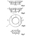
- Cap 60 which is inserted into anchoring plate 20 to secure the roofing membrane 58 (FIGS. 9 and 10) to anchoring plate 20, Referring mote particularly to FIGS. 3-5, a cap 60 of a first embodiment is illustrated.
- Cap 60 consists of a resilient cylindrical body 62 having a top end 64 and bottom end 66.
- Cylindrical body 62 has an outer wall 68 and an inner wall 70.
- Cylindrical body 62 has a longitudinal axis 72 about which inner wall 7 0 defines a concentric downwardly opening cylindrical cavity 74.
- Attached to the bottom end 66 is a V-shaped flange 76 which extends radially beyond the outer wall 68 around the entire circumference of cylindrical body 62.
- V-shaped flange 76 tapers inwardly from its top 75 to its bottom 77 .
- a plurality of compression cuts 78 extend through the cylindrical body and the V-shaped flange 76.
- Attached to the top end 64 of the cylindrical body 62 is a disk 8 0 which has an outside diameter 99 (FIG. 11) greater than the greatest diametrical dimension 97 of cylindrical body 62 and V-shaped flange 76.
- This disk 80 may be constructed with the radiused corners 82.
- FIGS. 6-8 there is illustrated a second embodiment, which at present is believed to be the preferred embodiment, of a cap 60 in accordance with the present invention.
- This cap also has a resilient cylindrical body 62 with a top end 64 and a bottom end 66 as well as an outer wall 68, an inner wall 70 and a longitudinal axis 72.
- this cap differs in that downwardly opening cylindrical cavity is also an upwardly opening cylindrical cavity 83 which is concentric about longitudinal axis 72. Since the cavity extends through what was the disk 80 in the first embodiment. in the second embodiment, there is a ring 84 attached to the top end 64 of the resilient cylindrical body 62. Additionally, there is a plug 86 sized to fit within the cylindrical cavity 83.
- the plug 86 has a taper 88 near the bottom 90 of the side walls 87 to ease the insertion of the plug into the cylindrical cavity 83. Additionally, in the bottom 90, there is a recess 92 of sufficient size to accommodate the head of the linear fastener 54.
- the plug 86 is of a length sufficient to allow the top surface 91 to be flush with the top surface 89 of ring 84 when the plug is inserted into cap 60 as is best illustrated in FIG. 10.
- FIGS. 9,10 and 11 The inter-relationship between the anchoring plate 20 and the cap 60 is best illustrated in FIGS. 9,10 and 11.
- the outside.diameter 93 of cylindrical body 62 is slightly less than the inside diameter 94 of cylindrical side surface of lip 38.
- the distance 95 between the bottom of the disk 80 or ring 84 to the top of the V-shaped flange 76 is slightly greater than the thickness 96 of the lip 38.
- the greatest diametrical dimension 97 of the cylindrical body 62 and the V-shaped flange 76 is slightly less than the inside diameter 98 of axial opening 34.
- the outside diameter 99 of disk 80 or ring 84 is substantially greater than the inside diameter 94 of cylindrical side surface 4 0 of lip 38.
- compression cut 78 is designed to allow the cylindrical body 62 of cap 60 to assume a first state illustrated in FIGS. 8, 4, 5. 10 and 11 wherein the sides 79 of the cut are parallel to one another. Additionally, the cap 60 can assume a second state best illustrated in FIG. 9 wherein the sides 79 of the cylindrical compression cut 78 converge toward bottom end 66 of the resilient cylindrical body 62. In the second state, the greatest diametrical dimension 97 of cylindrical body 62 and V-shaped flange 76 is diminished to be slightly less than the inside diameter 94 of cylindrical side surface 40 of lip 38.
- cap 60 This allows for the cap 60 to be inserted into anchoring plate 20 after membrane 58 has been extended across the anchoring plate 20 and inserted into axial opening 34.
- the cylindrical body 62 resumes its first state and the sides 79 of the compression cut 78 are once again parallel ( as illustrated by the dotted lines in FIG. 10) and the top of V-shaped flange 76 is received in channel 48.
- plug 86 may be inserted into cylindrical cavity 83 and thereby lock cylindrical body 62 into the first state so that the cap 60 cannot be inadvertently knocked out of the anchoring plate 20.
- Plug 86 and cylindrical cavity 83 may be designed so that plug 86 is driven into cylindrical cavity 83 or so that either or both plug 86 and cylindrical cavity 83 will have threads 100 which will allow the plug 86 to be screwed into cylindrical cavity 83. These threads 100 are illustrated by the dotted lines in FIGS. 7 and 8, while a smooth sided plug 86 and cylindrical cavity 83 are illustrated in the remainder of the drawings illustrating the second embodiment of cap 60 . As can be seen from FIGS. 9 and 10. the use of compression cut 78 and of the particular design of both the anchoring plate 20 and caps 60 allows the membrane 58 to be secured to the anchoring plate 20 which is secured to the structure 22 without membrane 58 being penetrated in any way so that the water-tight integrity of Membrane 58 is maintained.
- FIG. 10 best iliustrates that the anchoring system of the present invention is very low profile and therefore cannot be easily damaged by workers walking on the roof after or during installation.
- Anchor plate 20 because of radiused top surface 28, results in only slight and gradual deviation of the roof surface.
- Cap 60 does not protrude greatly beyond the roof membrane as only the thin ring 84 or disk 80 of cap 60 is not received within axial opening 34. Because so little of cap 60 protrudes above roofing membrane 58, there is very little chance that a blow sufficient to dislodge cap 60 could be administered by the foot of a worker walking on the roof.
- cap 60 and anchoring plate 20 may be manufactured or molded from a wide variety of materials.
- One material which is envisioned is a hard plastic because it is sufficiently flexible to be compressed, through the use of compression cuts 78, into the second state, yet rigid enough that once cap 60 and anchoring plate 20 are snapped together there will be secure attachment of roofing membrane 58 to structure 22.
Landscapes
- Engineering & Computer Science (AREA)
- Mechanical Engineering (AREA)
- Architecture (AREA)
- Civil Engineering (AREA)
- Structural Engineering (AREA)
- Roof Covering Using Slabs Or Stiff Sheets (AREA)
- Tents Or Canopies (AREA)
- Vehicle Interior And Exterior Ornaments, Soundproofing, And Insulation (AREA)
- Automobile Manufacture Line, Endless Track Vehicle, Trailer (AREA)
Priority Applications (1)
| Application Number | Priority Date | Filing Date | Title |
|---|---|---|---|
| AT87300178T ATE69851T1 (de) | 1986-05-22 | 1987-01-09 | Vorrichtung zum befestigen einer dachhaut auf einer konstruktion. |
Applications Claiming Priority (2)
| Application Number | Priority Date | Filing Date | Title |
|---|---|---|---|
| US06/865,765 US4658558A (en) | 1986-05-22 | 1986-05-22 | Apparatus for attaching roofing membrane to a structure |
| US865765 | 1986-05-22 |
Publications (3)
| Publication Number | Publication Date |
|---|---|
| EP0246720A2 true EP0246720A2 (de) | 1987-11-25 |
| EP0246720A3 EP0246720A3 (en) | 1989-03-29 |
| EP0246720B1 EP0246720B1 (de) | 1991-11-27 |
Family
ID=25346180
Family Applications (1)
| Application Number | Title | Priority Date | Filing Date |
|---|---|---|---|
| EP87300178A Expired EP0246720B1 (de) | 1986-05-22 | 1987-01-09 | Vorrichtung zum Befestigen einer Dachhaut auf einer Konstruktion |
Country Status (4)
| Country | Link |
|---|---|
| US (2) | US4658558A (de) |
| EP (1) | EP0246720B1 (de) |
| AT (1) | ATE69851T1 (de) |
| DE (1) | DE3774762D1 (de) |
Families Citing this family (32)
| Publication number | Priority date | Publication date | Assignee | Title |
|---|---|---|---|---|
| US4825613A (en) * | 1987-08-03 | 1989-05-02 | North American Roofing Company, Inc. | Non rotatable apparatus for securing roofing insulation blocks and an outer membrane |
| US4999963A (en) * | 1986-05-22 | 1991-03-19 | North American Roofing Company, Inc. | Apparatus for attaching roofing membrane to a structure |
| US4658558A (en) * | 1986-05-22 | 1987-04-21 | North American Roofing Company, Inc. | Apparatus for attaching roofing membrane to a structure |
| US4727699A (en) * | 1987-04-07 | 1988-03-01 | Sargent Richard G | Roofing membrane securement system |
| US4790037A (en) * | 1987-05-13 | 1988-12-13 | Air-Lok Pool Covers, Inc. | Swimming pool cover assembly |
| US4912895A (en) * | 1987-12-28 | 1990-04-03 | Ford Motor Company | Adjustable spacer |
| US4858412A (en) * | 1988-03-28 | 1989-08-22 | Kassem Gary M | Non-penetrating elastomeric membrane anchoring system |
| US4987714A (en) * | 1988-08-25 | 1991-01-29 | Lemke Stuart H | Method for installing a roof fastener |
| US5255485A (en) * | 1988-08-25 | 1993-10-26 | Stuart H. Lemke | Apparatus and method for installing roofing fasteners |
| JPH087138Y2 (ja) * | 1991-04-05 | 1996-03-04 | 日本精工株式会社 | リニアガイド装置のレール取付穴用キャップ |
| US5378102A (en) * | 1991-09-30 | 1995-01-03 | Sfs Stadler, Inc. | Barrel assembly and composite stress plate |
| JP3043237B2 (ja) * | 1993-11-24 | 2000-05-22 | ダイワ精工株式会社 | 魚釣用リール |
| SE502627C2 (sv) * | 1994-04-25 | 1995-11-27 | Sandvik Ab | Anordning för skydd mot överåtdragning av bultar, skruvar och dylikt |
| GB2315309B (en) * | 1996-07-12 | 2000-02-16 | Philip Denman | Device for restricting access to a head element of a fastener and method of using the device |
| DE19646951A1 (de) * | 1996-11-13 | 1998-05-14 | Hilti Ag | Befestigungselement |
| US20040209975A1 (en) * | 1997-04-02 | 2004-10-21 | Subelka John C. | Dental composite restorative material and method of restoring a tooth |
| US6262142B1 (en) | 1997-04-02 | 2001-07-17 | Dentsply Research & Development | Translucent wear resistant dental enamel material and method |
| US6353040B1 (en) | 1997-04-02 | 2002-03-05 | Dentsply Research & Development Corp. | Dental composite restorative material and method of restoring a tooth |
| US7797906B2 (en) * | 2007-10-22 | 2010-09-21 | Single Source Roofing Corporation | Non-penetrating elastomeric membrane anchoring system |
| JP4435821B2 (ja) * | 2007-10-30 | 2010-03-24 | 株式会社ホンダアクセス | 車載用物品支持具 |
| DE102007055878A1 (de) * | 2007-12-19 | 2009-06-25 | Hilti Aktiengesellschaft | Abdichtelement |
| JP5926649B2 (ja) * | 2012-08-13 | 2016-05-25 | フジモリ産業株式会社 | 防水シート取付具 |
| US9468399B2 (en) * | 2014-12-09 | 2016-10-18 | SensaRx, LLC | Detection of changes from a seated or lying body position by sensing body angle |
| US10781835B2 (en) | 2015-03-31 | 2020-09-22 | Tremco Incorporated | Mechanically detachable membrane for pre-applied waterproofing |
| US9765529B2 (en) * | 2015-09-11 | 2017-09-19 | Charles Porter | Panel fastener |
| US10190616B2 (en) | 2016-01-04 | 2019-01-29 | Celcore Incorporated | Roof cover fastener |
| US10781587B2 (en) | 2016-12-14 | 2020-09-22 | Solsera, Inc. | Structural attachment sealing system |
| USD844424S1 (en) | 2017-06-23 | 2019-04-02 | Celcore Incorporated | Roof cover fastener |
| US10767684B1 (en) | 2019-04-26 | 2020-09-08 | Solsera, Inc. | Flat roof mounting device |
| US11746821B2 (en) | 2019-04-26 | 2023-09-05 | Solsera, Inc. | Flat roof mounting device |
| US11962137B2 (en) | 2020-04-21 | 2024-04-16 | Unirac Inc. | Electric junction box mount apparatus |
| US20230279662A1 (en) * | 2022-03-07 | 2023-09-07 | Bmic Llc | Fastener systems for roof structures |
Family Cites Families (14)
| Publication number | Priority date | Publication date | Assignee | Title |
|---|---|---|---|---|
| DE1609328C3 (de) * | 1965-09-27 | 1975-12-04 | Hilti Ag, Schaan (Liechtenstein) | Vorrichtung zum Befestigen biegsam«! Flächengebilde, beispielsweise Kunststoffolien für Abdichtungszwecke, an einem Untergrund |
| FR2330901A1 (fr) * | 1975-11-04 | 1977-06-03 | Itw De France | Dispositif de fixation assurant l'etancheite |
| US4136598A (en) * | 1977-08-19 | 1979-01-30 | Hughes Rodney R | Snap-on cap and washer assembly |
| US4380413A (en) * | 1980-11-03 | 1983-04-19 | Illinois Tool Works Inc. | Load-distributive washer for use with compressible material |
| DE3134973C2 (de) * | 1981-01-23 | 1983-12-29 | Veith Pirelli AG, 6128 Höchst | Vorrichtung zur Befestigung einer flexiblen Bahn an einer Wandung |
| US4394096A (en) * | 1981-08-27 | 1983-07-19 | Menasha Corporation | Attachment system for plastic liners |
| US4455804A (en) * | 1982-02-19 | 1984-06-26 | Single-Ply Institute Of America, Inc. | Membrane anchor |
| US4520606A (en) * | 1983-01-27 | 1985-06-04 | Francovitch Thomas F | Roof membrane anchoring systems using dual anchor plates |
| US4519175A (en) * | 1983-06-15 | 1985-05-28 | Carlisle Corporation | Lubricated roofing membrane fastener |
| US4549331A (en) * | 1983-10-12 | 1985-10-29 | Plus One Ltd. | Button for receiving and securing a fabric covering therefor and fabric-covered button assembly formed therewith |
| US4543758A (en) * | 1984-02-22 | 1985-10-01 | Lane Bennie L | Rail and cap strip for securing rubber roof membrane to a deck without fastener penetrations |
| US4586301A (en) * | 1984-08-06 | 1986-05-06 | W. P. Hickman Company | Retainer clamp membrane fastening system |
| US4617771A (en) * | 1985-09-26 | 1986-10-21 | The Firestone Tire & Rubber Company | Mechanical fastener for roofing membrane and method of applying same |
| US4658558A (en) * | 1986-05-22 | 1987-04-21 | North American Roofing Company, Inc. | Apparatus for attaching roofing membrane to a structure |
-
1986
- 1986-05-22 US US06/865,765 patent/US4658558A/en not_active Expired - Lifetime
-
1987
- 1987-01-09 EP EP87300178A patent/EP0246720B1/de not_active Expired
- 1987-01-09 AT AT87300178T patent/ATE69851T1/de not_active IP Right Cessation
- 1987-01-09 DE DE8787300178T patent/DE3774762D1/de not_active Expired - Fee Related
- 1987-03-02 US US07/020,561 patent/US4777775A/en not_active Expired - Lifetime
Also Published As
| Publication number | Publication date |
|---|---|
| US4658558A (en) | 1987-04-21 |
| DE3774762D1 (de) | 1992-01-09 |
| EP0246720B1 (de) | 1991-11-27 |
| EP0246720A3 (en) | 1989-03-29 |
| ATE69851T1 (de) | 1991-12-15 |
| US4777775A (en) | 1988-10-18 |
Similar Documents
| Publication | Publication Date | Title |
|---|---|---|
| EP0246720A2 (de) | Vorrichtung zum Befestigen einer Dachhaut auf einer Konstruktion | |
| US4999963A (en) | Apparatus for attaching roofing membrane to a structure | |
| US4631887A (en) | Non-penetrating roof membrane anchoring system | |
| US4757662A (en) | Membrane roofing fastener | |
| US4727699A (en) | Roofing membrane securement system | |
| US5063722A (en) | Gripstay channel veneer anchor assembly | |
| US4694513A (en) | Drain | |
| US3971182A (en) | Portable wall assembly | |
| US4900208A (en) | Roofing fastener | |
| AU604528B2 (en) | Fastener assembly for a roof membrane | |
| US4972642A (en) | Footings for post or beam construction | |
| US5143498A (en) | Roofing fastening device | |
| US5267423A (en) | Self-drilling anchor and bearing plate assembly | |
| US4763456A (en) | Roof anchor and stress plate assembly | |
| US4686808A (en) | Roofing system, method and holddown apparatus | |
| US4881861A (en) | Fastening assembly | |
| US4653246A (en) | Insulation board for attachment to walls | |
| US5404682A (en) | Adjustable mounting for a post system | |
| US3545152A (en) | Concrete insert | |
| US4862664A (en) | Roofing fastener for fastener assembly and roof assemblies | |
| GB2070179A (en) | A plate suitable for use with a fastener to secure insulation to a roof deck | |
| US4617771A (en) | Mechanical fastener for roofing membrane and method of applying same | |
| US5255485A (en) | Apparatus and method for installing roofing fasteners | |
| US4619094A (en) | Non-penetrating mechanical fastener for roofing membrane and method of applying same | |
| GB2157788A (en) | Anchoring devices |
Legal Events
| Date | Code | Title | Description |
|---|---|---|---|
| PUAI | Public reference made under article 153(3) epc to a published international application that has entered the european phase |
Free format text: ORIGINAL CODE: 0009012 |
|
| AK | Designated contracting states |
Kind code of ref document: A2 Designated state(s): AT BE CH DE ES FR GB GR IT LI LU NL SE |
|
| PUAL | Search report despatched |
Free format text: ORIGINAL CODE: 0009013 |
|
| AK | Designated contracting states |
Kind code of ref document: A3 Designated state(s): AT BE CH DE ES FR GB GR IT LI LU NL SE |
|
| 17P | Request for examination filed |
Effective date: 19890510 |
|
| 17Q | First examination report despatched |
Effective date: 19891109 |
|
| RAP1 | Party data changed (applicant data changed or rights of an application transferred) |
Owner name: NORTH AMERICAN ROOFING SYSTEMS, INC. |
|
| RAP3 | Party data changed (applicant data changed or rights of an application transferred) |
Owner name: NORTH AMERICAN ROOFING SYSTEMS, INC. |
|
| GRAA | (expected) grant |
Free format text: ORIGINAL CODE: 0009210 |
|
| AK | Designated contracting states |
Kind code of ref document: B1 Designated state(s): AT BE CH DE ES FR GB GR IT LI LU NL SE |
|
| PG25 | Lapsed in a contracting state [announced via postgrant information from national office to epo] |
Ref country code: IT Free format text: LAPSE BECAUSE OF FAILURE TO SUBMIT A TRANSLATION OF THE DESCRIPTION OR TO PAY THE FEE WITHIN THE PRE;WARNING: LAPSES OF ITALIAN PATENTS WITH EFFECTIVE DATE BEFORE 2007 MAY HAVE OCCURRED AT ANY TIME BEFORE 2007. THE CORRECT EFFECTIVE DATE MAY BE DIFFERENT FROM THE ONE RECORDED.SCRIBED TIME-LIMIT Effective date: 19911127 Ref country code: GR Free format text: LAPSE BECAUSE OF FAILURE TO SUBMIT A TRANSLATION OF THE DESCRIPTION OR TO PAY THE FEE WITHIN THE PRESCRIBED TIME-LIMIT Effective date: 19911127 Ref country code: BE Effective date: 19911127 Ref country code: LI Effective date: 19911127 Ref country code: CH Effective date: 19911127 Ref country code: SE Effective date: 19911127 Ref country code: AT Effective date: 19911127 Ref country code: NL Effective date: 19911127 |
|
| REF | Corresponds to: |
Ref document number: 69851 Country of ref document: AT Date of ref document: 19911215 Kind code of ref document: T |
|
| REF | Corresponds to: |
Ref document number: 3774762 Country of ref document: DE Date of ref document: 19920109 |
|
| PG25 | Lapsed in a contracting state [announced via postgrant information from national office to epo] |
Ref country code: LU Free format text: LAPSE BECAUSE OF NON-PAYMENT OF DUE FEES Effective date: 19920131 |
|
| PG25 | Lapsed in a contracting state [announced via postgrant information from national office to epo] |
Ref country code: ES Free format text: LAPSE BECAUSE OF FAILURE TO SUBMIT A TRANSLATION OF THE DESCRIPTION OR TO PAY THE FEE WITHIN THE PRESCRIBED TIME-LIMIT Effective date: 19920310 |
|
| REG | Reference to a national code |
Ref country code: CH Ref legal event code: PL |
|
| EN | Fr: translation not filed | ||
| PG25 | Lapsed in a contracting state [announced via postgrant information from national office to epo] |
Ref country code: FR Effective date: 19920417 |
|
| NLV1 | Nl: lapsed or annulled due to failure to fulfill the requirements of art. 29p and 29m of the patents act | ||
| PG25 | Lapsed in a contracting state [announced via postgrant information from national office to epo] |
Ref country code: DE Effective date: 19921001 |
|
| PLBE | No opposition filed within time limit |
Free format text: ORIGINAL CODE: 0009261 |
|
| STAA | Information on the status of an ep patent application or granted ep patent |
Free format text: STATUS: NO OPPOSITION FILED WITHIN TIME LIMIT |
|
| 26N | No opposition filed | ||
| REG | Reference to a national code |
Ref country code: FR Ref legal event code: ST |
|
| PGFP | Annual fee paid to national office [announced via postgrant information from national office to epo] |
Ref country code: GB Payment date: 19981218 Year of fee payment: 13 |
|
| PG25 | Lapsed in a contracting state [announced via postgrant information from national office to epo] |
Ref country code: GB Free format text: LAPSE BECAUSE OF NON-PAYMENT OF DUE FEES Effective date: 20000109 |
|
| GBPC | Gb: european patent ceased through non-payment of renewal fee |
Effective date: 20000109 |