EP0246496A2 - Tire curing system - Google Patents
Tire curing system Download PDFInfo
- Publication number
- EP0246496A2 EP0246496A2 EP87106584A EP87106584A EP0246496A2 EP 0246496 A2 EP0246496 A2 EP 0246496A2 EP 87106584 A EP87106584 A EP 87106584A EP 87106584 A EP87106584 A EP 87106584A EP 0246496 A2 EP0246496 A2 EP 0246496A2
- Authority
- EP
- European Patent Office
- Prior art keywords
- curing
- loading
- units
- path
- unloading
- Prior art date
- Legal status (The legal status is an assumption and is not a legal conclusion. Google has not performed a legal analysis and makes no representation as to the accuracy of the status listed.)
- Granted
Links
- 238000010438 heat treatment Methods 0.000 claims abstract description 10
- 230000005484 gravity Effects 0.000 claims description 5
- 230000008878 coupling Effects 0.000 claims description 4
- 238000010168 coupling process Methods 0.000 claims description 4
- 238000005859 coupling reaction Methods 0.000 claims description 4
- 238000004519 manufacturing process Methods 0.000 description 5
- 238000011144 upstream manufacturing Methods 0.000 description 3
- 230000005540 biological transmission Effects 0.000 description 2
- 230000009977 dual effect Effects 0.000 description 2
- 229920001971 elastomer Polymers 0.000 description 2
- 239000000806 elastomer Substances 0.000 description 2
- 238000001914 filtration Methods 0.000 description 2
- 238000003754 machining Methods 0.000 description 2
- 230000002035 prolonged effect Effects 0.000 description 2
- IJGRMHOSHXDMSA-UHFFFAOYSA-N Atomic nitrogen Chemical compound N#N IJGRMHOSHXDMSA-UHFFFAOYSA-N 0.000 description 1
- 241000722921 Tulipa gesneriana Species 0.000 description 1
- 229910001873 dinitrogen Inorganic materials 0.000 description 1
- 238000000605 extraction Methods 0.000 description 1
- 239000007789 gas Substances 0.000 description 1
- 239000000463 material Substances 0.000 description 1
- 238000000034 method Methods 0.000 description 1
- 230000002093 peripheral effect Effects 0.000 description 1
- 238000000746 purification Methods 0.000 description 1
- 230000001105 regulatory effect Effects 0.000 description 1
- 230000000284 resting effect Effects 0.000 description 1
- 230000000717 retained effect Effects 0.000 description 1
- 238000007789 sealing Methods 0.000 description 1
- 238000007493 shaping process Methods 0.000 description 1
- XLYOFNOQVPJJNP-UHFFFAOYSA-N water Substances O XLYOFNOQVPJJNP-UHFFFAOYSA-N 0.000 description 1
Images


Classifications
-
- B—PERFORMING OPERATIONS; TRANSPORTING
- B29—WORKING OF PLASTICS; WORKING OF SUBSTANCES IN A PLASTIC STATE IN GENERAL
- B29C—SHAPING OR JOINING OF PLASTICS; SHAPING OF MATERIAL IN A PLASTIC STATE, NOT OTHERWISE PROVIDED FOR; AFTER-TREATMENT OF THE SHAPED PRODUCTS, e.g. REPAIRING
- B29C33/00—Moulds or cores; Details thereof or accessories therefor
- B29C33/02—Moulds or cores; Details thereof or accessories therefor with incorporated heating or cooling means
-
- B—PERFORMING OPERATIONS; TRANSPORTING
- B29—WORKING OF PLASTICS; WORKING OF SUBSTANCES IN A PLASTIC STATE IN GENERAL
- B29D—PRODUCING PARTICULAR ARTICLES FROM PLASTICS OR FROM SUBSTANCES IN A PLASTIC STATE
- B29D30/00—Producing pneumatic or solid tyres or parts thereof
- B29D30/005—General arrangement or lay-out of plants for the processing of tyres or parts thereof
-
- B—PERFORMING OPERATIONS; TRANSPORTING
- B29—WORKING OF PLASTICS; WORKING OF SUBSTANCES IN A PLASTIC STATE IN GENERAL
- B29C—SHAPING OR JOINING OF PLASTICS; SHAPING OF MATERIAL IN A PLASTIC STATE, NOT OTHERWISE PROVIDED FOR; AFTER-TREATMENT OF THE SHAPED PRODUCTS, e.g. REPAIRING
- B29C33/00—Moulds or cores; Details thereof or accessories therefor
- B29C33/34—Moulds or cores; Details thereof or accessories therefor movable, e.g. to or from the moulding station
- B29C33/36—Moulds or cores; Details thereof or accessories therefor movable, e.g. to or from the moulding station continuously movable in one direction, e.g. in a closed circuit
-
- B—PERFORMING OPERATIONS; TRANSPORTING
- B29—WORKING OF PLASTICS; WORKING OF SUBSTANCES IN A PLASTIC STATE IN GENERAL
- B29C—SHAPING OR JOINING OF PLASTICS; SHAPING OF MATERIAL IN A PLASTIC STATE, NOT OTHERWISE PROVIDED FOR; AFTER-TREATMENT OF THE SHAPED PRODUCTS, e.g. REPAIRING
- B29C35/00—Heating, cooling or curing, e.g. crosslinking or vulcanising; Apparatus therefor
- B29C35/02—Heating or curing, e.g. crosslinking or vulcanizing during moulding, e.g. in a mould
-
- B—PERFORMING OPERATIONS; TRANSPORTING
- B29—WORKING OF PLASTICS; WORKING OF SUBSTANCES IN A PLASTIC STATE IN GENERAL
- B29D—PRODUCING PARTICULAR ARTICLES FROM PLASTICS OR FROM SUBSTANCES IN A PLASTIC STATE
- B29D30/00—Producing pneumatic or solid tyres or parts thereof
-
- B—PERFORMING OPERATIONS; TRANSPORTING
- B29—WORKING OF PLASTICS; WORKING OF SUBSTANCES IN A PLASTIC STATE IN GENERAL
- B29D—PRODUCING PARTICULAR ARTICLES FROM PLASTICS OR FROM SUBSTANCES IN A PLASTIC STATE
- B29D30/00—Producing pneumatic or solid tyres or parts thereof
- B29D30/06—Pneumatic tyres or parts thereof (e.g. produced by casting, moulding, compression moulding, injection moulding, centrifugal casting)
- B29D30/0601—Vulcanising tyres; Vulcanising presses for tyres
- B29D30/065—Tyre-vulcanising presses with two or more moulds, e.g. stacked upon each other
- B29D2030/0651—Tyre-vulcanising presses with two or more moulds, e.g. stacked upon each other the moulds being arranged side by side, or in a circle
-
- B—PERFORMING OPERATIONS; TRANSPORTING
- B29—WORKING OF PLASTICS; WORKING OF SUBSTANCES IN A PLASTIC STATE IN GENERAL
- B29D—PRODUCING PARTICULAR ARTICLES FROM PLASTICS OR FROM SUBSTANCES IN A PLASTIC STATE
- B29D30/00—Producing pneumatic or solid tyres or parts thereof
- B29D30/06—Pneumatic tyres or parts thereof (e.g. produced by casting, moulding, compression moulding, injection moulding, centrifugal casting)
- B29D30/0601—Vulcanising tyres; Vulcanising presses for tyres
- B29D30/0662—Accessories, details or auxiliary operations
- B29D2030/0666—Heating by using fluids
- B29D2030/0667—Circulating the fluids, e.g. introducing and removing them into and from the moulds; devices therefor
- B29D2030/067—Circulating the fluids, e.g. introducing and removing them into and from the moulds; devices therefor the vulcanizing fluids being gases or vapours
-
- B—PERFORMING OPERATIONS; TRANSPORTING
- B29—WORKING OF PLASTICS; WORKING OF SUBSTANCES IN A PLASTIC STATE IN GENERAL
- B29L—INDEXING SCHEME ASSOCIATED WITH SUBCLASS B29C, RELATING TO PARTICULAR ARTICLES
- B29L2030/00—Pneumatic or solid tyres or parts thereof
Definitions
- the present invention relates to a tire curing system.
- Such systems are known to generally present one or two molds, each comprising top and bottom mold halves defining an annular chamber for a green tire.
- the top mold half is usually connected to a moving crosspiece on the press, whereas the bottom mold half is mounted on the bed of the press and supports a deformable inner tube or curing bladder designed to occupy the said annular chamber when inflated with a heat-exchanging curing media.
- the said curing media usually consisting of relatively hot steam, is supplied under pressure by an external feeder, which provides for heating the curing media, possibly after producing and filtering it, and circulating it under pressure inside the mold for the length of time required for curing.
- a major drawback of known systems of the aforementioned type is that they involve relatively high manufacturing cost and provide for relatively low output. Such systems in fact require a relatively high-cost press for every one or two molds, which press remains engaged throughout the entire curing operation.
- systems comprising a number of molds mounted in a fixed manner on an indexing fixture which, turning about a fixed vertical axis, feeds the molds, one by one, through a loading station where each mold is opened, loaded and closed by a fastening device on the mold itself.
- Each mold is then turned on the indexing fixture and supplied, as long as required for curing, with steam under pressure fed from a centralized feeding device connected to all the molds on the indexing fixture.
- a tire curing system characterized by the fact that it comprises a number of mobile curing units, each designed to house a respective green tire; loading means and unloading means for respectively loading.said tires on and unloading said tires off respective ones of said curing units, a loop path for the said units; guide means for said mobile curing units, said guide means defining a path extending between said loading means and said unloading means; means for selectively feeding the said units along the said path; and individual coupling means provided on each said curing unit for releasably and independently coupling the same to said guide means; each of said curing units incorporating a mold for a respective green tire, a closed circuit designed to receive, at the said loading means, a given supply of curing media under pressure, means for force circulating the said curing media supply inside the said closed circuit, and individual elements for heating both the said mold and the said curing media supply.
- Numeral 1 in Fig. 1 indicates a system for curing tires 2, said system comprising a number of mobile curing units 3, each designed to receive a respective tire 2.
- Each unit 3 is mounted in a fixed manner on a respective carriage 4 mounted on rollers 5 enabling carriage 4 to travel along two tubular rails 6 defining a loop path or circuit 7 along which mobile units 3 are fed in the direction indicated by arrow 8.
- Circuit 7 comprises a first portion 9, extending through a station 10 for loading and unloading tires 2 on and off respective units 3, and a second portion 11 comprising two branches 12 and 13 arranged in parallel.
- the upstream end of each branch 12 and 13, in the travelling direction of units 3, is selectively connectable to a downstream end of circuit portion 9 by means of a switch device 14 comprising a rail section 15 designed to move between two different operating positions by virtue of actuator 16.
- the downstream ends of branches 12 and 13 are connected to the upstream end of portion 9 by means of a three-way intersection 17 controlled by a locking device 18 designed to move selectively between two operating positions, for selectively closing the outlet of either of branches 12 and 13.
- both branches 12 and 13 slope downwardly, and portion 9 of circuit 7 is divided into two downward-sloping sections 19 and 20.
- section 19 extends downwards through station 10, and presents a downstream end lower than the upstream end of section 20 to which it is connected by a lift 21 supporting a rail section 22 and designed to move vertically between two different operating positions, by virtue of actuator 23.
- each mobile curing unit 3 comprises a mold 24 consisting of a bottom mold half 25 and a top mold half 26, both annular and interconnected by a bayonet joint 27 in the form of an outer ring 28 surrounding mold 24.
- Ring 28 includes an outer extension 29 (Fig.2) which may be acted on for turning ring 28 about mold 24 and between a locking position, wherein ring 28 locks together, in contacting manner, an outer annular flange 30 on mold half 25 and a number of wedge-shaped teeth 31 extending radially outwardly of mold half 26, and an opening position, wherein ring 28 presents slots 32 facing teeth 31, thus enabling axial detachment of mold half 26 from mold half 25.
- Fig.2 an outer extension 29
- bottom mold half 25 is formed in two annular pieces 81 and 82, the first consisting of a cup-shaped outer casing and being provided with annular flange 30, and the second consisting of a torus constituting the the bottom mold half proper.
- Torus 82 is mounted inside casing 81 so as to slide towards mold half 26 under the thrust of a flexible compensating member 83 housed inside a variable-volume annular chamber 84 defined between the lower surface of torus 82 and the upper surface of the end wall of casing 81.
- flexible member 83 consists of a layer of flexibile material which may obviously be replaced, in variations not shown, for example, by set springs or gas under pressure.
- mold half 25 On its inner edge, mold half 25 presents a top annular groove 33 defining a supporting seat for annular body 34.
- Casing 38 houses, at the bottom, a fan 39 having a drive motor 40, and comprises a substantially cylindrical side wall 41 a top portion of which engages, in radially slack manner, a center hole 42 on mold half 25, in such a manner as to define an annular sliding slit 43 for a cylindrical tubular piston 44 the outside diameter of which is smaller than the inside diameter of tire 2.
- piston 44 faces holes 37 and is connected, at the top, to annular body 34, which acts as a stop for arresting the downward axial slide of piston 44 and, at the same time, as an extracting element for extracting tire 2 from mold half 25.
- Side wall 41 is closed at the top by a cap 45 which is fitted over hole 42.
- the top portion of cap 45 and the top portion of wall 41 are fitted respectively with a top annular fastening element 46 and a bottom annular fastening element 47 for respectively fastening the top and bottom edges of an annular inner tube or curing bladder 48 made of elastomer, having a substantially C-shaped radial half section and designed to expand inside tire 2.
- Annular fastening elements 46 and 47 present respective outside diameters smaller than the inside diameter of tubular piston 44, and are separated by a flat annular lip 49 made of elastomer, the inner edge of which is secured to the outer peripheral surface of cap 45.
- Casing 38 is fitted inside with a heating element 50 having a number of through axial channels 51 and dividing the space inside casing 38 into a top chamber 52 and a bottom chamber 53.
- Chambers 52 and 53 communicate with the space inside inner tube 48 via respective rows of holes 54 and 55 formed respectively through the top of wall 41 above lip 49 and through wall 41 below lip 49.
- Chamber 53 and housing fan 39 define, together with channels 51, chamber 52, the space inside inner tube 48, and holes 54 and 55, a closed pneumatic circuit 56 for circulating a given supply of heat-exchanging curing media, preferably nitrogen gas, injected externally, at loading station 10, through a supply/exhaust valve 57 mounted on the bottom wall portion of casing 38.
- a closed pneumatic circuit 56 for circulating a given supply of heat-exchanging curing media, preferably nitrogen gas, injected externally, at loading station 10, through a supply/exhaust valve 57 mounted on the bottom wall portion of casing 38.
- Molds halves 25 and 26 are fitted with electrical heating resistors 58 connected, together with heating element 50 and motor 40, to an external electrical power source (not shown) by means of a connector 59 located outside mold 24 and connected, in sliding manner, to a power supply and control data transmission rail 60 extending along rail 6.
- station 10 comprises a portal or superstructure 61 through which run rails..6 and which is fitted with a locking device 62 for arresting each carriage 4 in a given loading/unloading position underneath portal 61.
- a carriage 4 in the said loading/unloading position its respective curing unit 3 is positioned with its top mold half 26 directly beneath a lifting device 63 comprising a magnetic head 64 and an actuating device 65 supported on the upper crosspiece of portal 61 and designed to move head 64 from a lowered position, contacting top mold half 26, connected to bottom mold half 25, into a raised position.
- a lifting device 63 comprising a magnetic head 64 and an actuating device 65 supported on the upper crosspiece of portal 61 and designed to move head 64 from a lowered position, contacting top mold half 26, connected to bottom mold half 25, into a raised position.
- respective curing unit 3 moves into position with extension 29, of its outer ring 28 engaging a pair of horizontal actuators 66 which may be operated for turning outer ring 28 on mold 24 between two operating positions for respectively opening and closing bayonet joint 27.
- each of holes 37 on bell 35 is located over a respective actuator or vertical hydraulic cylinder 67 mounted in a fixed manner underneath portal 61 and designed to move piston 44 between a normal lowered position and a raised extraction and loading position.
- valve 57 is located over an ejector 68 on a pneumatic loading circuit, which ejector is located beneath portal 61 and designed to move, by virtue of actuator 68a, between a lowered idle position and a raised position. In the latter position, ejector 68 engages valve 57 in such a manner as to open it, exhaust the said curing media inside unit 3 and subsequently inject a new supply of curing media.
- loading station 10 also includes a loading robot 69, which is located adjacent to portal 61 and includes a supporting body 70, a platform 71 mounted on supporting body 70 and turning in relation to the same about a vertical axis, and an articulated arm 72 mounted on platform 71 for moving, in relation to the same and in a substantially vertical plane, a known type of ring fastening device 73 comprising an outer ring 74 having a number of inner radial pistons 75 designed to engage the tread surface of a tire 2.
- a loading robot 69 which is located adjacent to portal 61 and includes a supporting body 70, a platform 71 mounted on supporting body 70 and turning in relation to the same about a vertical axis, and an articulated arm 72 mounted on platform 71 for moving, in relation to the same and in a substantially vertical plane, a known type of ring fastening device 73 comprising an outer ring 74 having a number of inner radial pistons 75 designed to engage the tread surface of a tire 2.
- system 1 as described also includes a thermally insulated outer case 76 for retaining the heat given off by units 3 during curing.
- System 1 may be operated in two ways, depending on whether it is supplied with one or two types of tires.
- unit 3 With unit 3 in the loading/unloading position beneath portal 61, its respective connector 59 engages a section 77 of rail 60, said section 77 enabling only the transmission of control signals, and no supply of electrical power to unit 3.
- Ejector 68 is raised for releasing the pressurized curing media charge inside unit 3, after which, horizontal actuators 66 are activated so as to turn ring 28 and open bayonet joint 27, and lifting device 63 is moved down so as to engage magnetic head 64 with top mold half 26. Mold 24 is then opened, by lifting up magnetic head 64 and top mold half 26.
- actuators 67 are operated for pushing up piston 44 which performs a dual function by first deforming inner tube 48 into a "tulip" shape and extracting it from cured tire 2, and then lifting tire 2 out and over bottom mold half 25 into ring 74 on fastening device 73 already positioned between raised top mold half 26 and bottom mold half 25. Subsequent to the operation of pistons 75, cured tire 2 is gripped by fastening device 73 and carried, by the operation of robot 69, over to an unloading table (not shown).
- Robot 69 then grasps a green tire 2 off a supply conveyor (not shown) and after conveying same, releases it onto open bottom mold half 25, specifically on annular body 34 on piston 44 held up by actuators 67. Actuators 67 are then lowered for lowering piston 44, which performs a dual function by first reinserting annular body 34 inside respective groove 33 and placing green tire 2 onto bottom mold half 25, as well as releasing inner tube 48 which is thereafter supplied by ejector 68 with a relatively low-pressure "shaping charge" for inflating inner tube 48 and inserting it inside green tire 2.
- top mold half 26 is lowered onto bottom mold half 25 and released by magnetic head 64, with actuators 66 being operated for closing bayonet joint 27.
- the rest of the curing media charge is injected by ejector 68, and unit 3, now fully released, is allowed to run down, by force of gravity, along section 19 of portion 9 of circuit 7, by releasing device 62.
- Rails 6, extending along circuit section 19, are usually occupied by further units 3 resting against one another and against a lock gate 78 at the entry to lift 21 designed to transfer units 3 one at a time from section 19 to section 20, at a rate depending on the required curing time.
- unit 3 After travelling along branch 12 or 13, unit 3 proceeds by force of gravity through intersection 17, along an initial portion of circuit section 19, and stops against a lock gate 79 which opens to let one unit 3 at a time into station 10 where it is stopped against lock device 62.
- the time taken for any unit 3 to travel the whole circuit 7 is regulated mainly by lift 21, in such a manner as to exactly equal the time required for curing its tire 2.
- a few units 3 are kept idle by locking device 18 on whichever of branches 12 and 13 is not being employed at the time.
- such units may be set up for receiving tires of different design from tires 2 being processed at the time on system 1, thus enabling production change by simply operating locking device 18 and switch device 14.
- station 10 may be supplied with a succession of units 3 for tires 2 of different designs, thus operating system 1 in the aforementioned second operating mode.
- branches 12 and 13 may obviously be operated for curing tires of a given number of different designs, either simultaneously or successively.
- system 1 provides for a high degree of versatility, while at the same time eliminating downtime for production changes, by virtue of the design of units 3, each of which, is fully independent of both other units 3 as well as station 10, and may be handled in any manner along circuit 7.
- a further advantage of system 1, and one not to be underestimated, is that the heat given off by curing units 3 is retained by outer casing 76 and partly absorbed by stand-by units 3 which, when operated, are thus preheated and require relatively little energy for attaining the required curing temperature.
Abstract
Description
- The present invention relates to a tire curing system.
- Such systems are known to generally present one or two molds, each comprising top and bottom mold halves defining an annular chamber for a green tire. The top mold half is usually connected to a moving crosspiece on the press, whereas the bottom mold half is mounted on the bed of the press and supports a deformable inner tube or curing bladder designed to occupy the said annular chamber when inflated with a heat-exchanging curing media. The said curing media, usually consisting of relatively hot steam, is supplied under pressure by an external feeder, which provides for heating the curing media, possibly after producing and filtering it, and circulating it under pressure inside the mold for the length of time required for curing.
- A major drawback of known systems of the aforementioned type is that they involve relatively high manufacturing cost and provide for relatively low output. Such systems in fact require a relatively high-cost press for every one or two molds, which press remains engaged throughout the entire curing operation.
- Furthermore, the slightest change in design entails relatively prolonged downtime for machining, during which time the press remains idle. Also, if the heat-exchanging curing media employed consists, as it does in all known present cases, of relatively hot steam, systems of the aforementioned type must therefore include an extremely high-cost accessory system for water purification and steam production.
- For partially overcoming these drawbacks, systems have been devised comprising a number of molds mounted in a fixed manner on an indexing fixture which, turning about a fixed vertical axis, feeds the molds, one by one, through a loading station where each mold is opened, loaded and closed by a fastening device on the mold itself. Each mold is then turned on the indexing fixture and supplied, as long as required for curing, with steam under pressure fed from a centralized feeding device connected to all the molds on the indexing fixture.
- Though systems of the aforementioned type involve no presses and provide for using a large number of molds at the same time, they are nevertheless extremely expensive in that they also require a separate system for filtering, producing, heating and supplying steam, as well as a number of sliding joints for connecting each moving mold to the said system. Furthermore, the said indexing fixture, to which the bottom half of each mold is necessarily integrally connected, imposes the same supply route and the same curing time for each mold, with no possibility of selective curing.
- Finally, in this case also, the slightest change in design entails relatively prolonged downtime during which the system remains idle.
- It is an object of the present invention to provide a curing system involving none of the aforementioned drawbacks, and which provides for a high degree of production flexibility.
- In particular, it is an object of the present invention to provide a system which may be operated selectively for enabling either sequence curing of tires of different design, or curing of a given design and switching to another with substantially no downtime involved for machining.
- According to the present invention, there is provided a tire curing system, characterized by the fact that it comprises a number of mobile curing units, each designed to house a respective green tire; loading means and unloading means for respectively loading.said tires on and unloading said tires off respective ones of said curing units, a loop path for the said units; guide means for said mobile curing units, said guide means defining a path extending between said loading means and said unloading means; means for selectively feeding the said units along the said path; and individual coupling means provided on each said curing unit for releasably and independently coupling the same to said guide means; each of said curing units incorporating a mold for a respective green tire, a closed circuit designed to receive, at the said loading means, a given supply of curing media under pressure, means for force circulating the said curing media supply inside the said closed circuit, and individual elements for heating both the said mold and the said curing media supply.
- The invention will now be described by way of example with reference to the attached drawings in which:
- - Figure 1 is a schematic perspective view of a tire curing system in accordance with the present invention;
- - Figure 2 is a schematic perspective view of a loading station in Figure 1; and
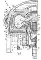
- - Figure 3 is an axial half section of a curing unit used in the curing system shown in Figure 1.
- Numeral 1 in Fig. 1 indicates a system for curing
tires 2, said system comprising a number ofmobile curing units 3, each designed to receive arespective tire 2. - For a detailed description of curing
unit 3, reference should be made to co-pending U.S. Application Serial No...(51-H).. filed concurrently herewith by the Assignee of the present invention and which is incorporated herein by reference in the interest of full disclosure. - Each
unit 3 is mounted in a fixed manner on a respective carriage 4 mounted onrollers 5 enabling carriage 4 to travel along two tubular rails 6 defining a loop path or circuit 7 along whichmobile units 3 are fed in the direction indicated by arrow 8. - Circuit 7 comprises a
first portion 9, extending through a station 10 for loading and unloadingtires 2 on and offrespective units 3, and a second portion 11 comprising twobranches 12 and 13 arranged in parallel. The upstream end of eachbranch 12 and 13, in the travelling direction ofunits 3, is selectively connectable to a downstream end ofcircuit portion 9 by means of aswitch device 14 comprising a rail section 15 designed to move between two different operating positions by virtue of actuator 16. The downstream ends ofbranches 12 and 13 are connected to the upstream end ofportion 9 by means of a three-way intersection 17 controlled by a locking device 18 designed to move selectively between two operating positions, for selectively closing the outlet of either ofbranches 12 and 13. - As shown in Fig. 1, both
branches 12 and 13 slope downwardly, andportion 9 of circuit 7 is divided into two downward-sloping sections 19 and 20. In more detail, from intersection 17, section 19 extends downwards through station 10, and presents a downstream end lower than the upstream end of section 20 to which it is connected by a lift 21 supporting a rail section 22 and designed to move vertically between two different operating positions, by virtue of actuator 23. - As shown in Fig. 3, each
mobile curing unit 3 comprises amold 24 consisting of abottom mold half 25 and atop mold half 26, both annular and interconnected by abayonet joint 27 in the form of anouter ring 28 surroundingmold 24. -
Ring 28 includes an outer extension 29 (Fig.2) which may be acted on for turningring 28 aboutmold 24 and between a locking position, wherein ring 28 locks together, in contacting manner, an outerannular flange 30 onmold half 25 and a number of wedge-shaped teeth 31 extending radially outwardly ofmold half 26, and an opening position, whereinring 28 presentsslots 32 facingteeth 31, thus enabling axial detachment ofmold half 26 frommold half 25. - For ensuring efficient sealing at all times during curing, between
mold halves bottom mold half 25 is formed in twoannular pieces annular flange 30, and the second consisting of a torus constituting the the bottom mold half proper. Torus 82 is mounted insidecasing 81 so as to slide towardsmold half 26 under the thrust of a flexible compensatingmember 83 housed inside a variable-volumeannular chamber 84 defined between the lower surface oftorus 82 and the upper surface of the end wall ofcasing 81. - In the example shown,
flexible member 83 consists of a layer of flexibile material which may obviously be replaced, in variations not shown, for example, by set springs or gas under pressure. - On its inner edge,
mold half 25 presents a top annular groove 33 defining a supporting seat for annular body 34. - To the bottom surface of
mold half 25 is connected the top flanged end of abell 35 coaxial withmold 24. Anend wall 36 onbell 35 presents a number of throughholes 37 and supports a bottom portion of a substantiallycylindrical casing 38. - Casing 38 houses, at the bottom, a
fan 39 having adrive motor 40, and comprises a substantially cylindrical side wall 41 a top portion of which engages, in radially slack manner, a center hole 42 onmold half 25, in such a manner as to define an annularsliding slit 43 for a cylindricaltubular piston 44 the outside diameter of which is smaller than the inside diameter oftire 2. At the bottom,piston 44 facesholes 37 and is connected, at the top, to annular body 34, which acts as a stop for arresting the downward axial slide ofpiston 44 and, at the same time, as an extracting element for extractingtire 2 frommold half 25. -
Side wall 41 is closed at the top by acap 45 which is fitted over hole 42. The top portion ofcap 45 and the top portion ofwall 41 are fitted respectively with a topannular fastening element 46 and a bottomannular fastening element 47 for respectively fastening the top and bottom edges of an annular inner tube or curing bladder 48 made of elastomer, having a substantially C-shaped radial half section and designed to expand insidetire 2. -
Annular fastening elements tubular piston 44, and are separated by a flatannular lip 49 made of elastomer, the inner edge of which is secured to the outer peripheral surface ofcap 45. -
Casing 38 is fitted inside with aheating element 50 having a number of throughaxial channels 51 and dividing the space insidecasing 38 into atop chamber 52 and abottom chamber 53. Chambers 52 and 53 communicate with the space inside inner tube 48 via respective rows ofholes wall 41 abovelip 49 and throughwall 41 belowlip 49. -
Chamber 53 andhousing fan 39 define, together withchannels 51,chamber 52, the space inside inner tube 48, andholes pneumatic circuit 56 for circulating a given supply of heat-exchanging curing media, preferably nitrogen gas, injected externally, at loading station 10, through a supply/exhaust valve 57 mounted on the bottom wall portion ofcasing 38. -
Molds halves electrical heating resistors 58 connected, together withheating element 50 andmotor 40, to an external electrical power source (not shown) by means of aconnector 59 located outsidemold 24 and connected, in sliding manner, to a power supply and controldata transmission rail 60 extending along rail 6. - As shown in Fig. 2, station 10 comprises a portal or
superstructure 61 through which run rails..6 and which is fitted with alocking device 62 for arresting each carriage 4 in a given loading/unloading position underneathportal 61. - With a carriage 4 in the said loading/unloading position, its
respective curing unit 3 is positioned with itstop mold half 26 directly beneath alifting device 63 comprising amagnetic head 64 and an actuatingdevice 65 supported on the upper crosspiece ofportal 61 and designed to movehead 64 from a lowered position, contactingtop mold half 26, connected tobottom mold half 25, into a raised position. - With a carriage 4 in the said loading/unloading position,
respective curing unit 3 moves into position withextension 29, of itsouter ring 28 engaging a pair ofhorizontal actuators 66 which may be operated for turningouter ring 28 onmold 24 between two operating positions for respectively opening and closingbayonet joint 27. Also, each ofholes 37 onbell 35 is located over a respective actuator or verticalhydraulic cylinder 67 mounted in a fixed manner underneathportal 61 and designed to movepiston 44 between a normal lowered position and a raised extraction and loading position. Finally,valve 57 is located over anejector 68 on a pneumatic loading circuit, which ejector is located beneathportal 61 and designed to move, by virtue ofactuator 68a, between a lowered idle position and a raised position. In the latter position,ejector 68 engagesvalve 57 in such a manner as to open it, exhaust the said curing media insideunit 3 and subsequently inject a new supply of curing media. - As shown in Fig. 1, loading station 10 also includes a loading robot 69, which is located adjacent to
portal 61 and includes a supportingbody 70, a platform 71 mounted on supportingbody 70 and turning in relation to the same about a vertical axis, and an articulatedarm 72 mounted on platform 71 for moving, in relation to the same and in a substantially vertical plane, a known type ofring fastening device 73 comprising an outer ring 74 having a number of innerradial pistons 75 designed to engage the tread surface of atire 2. - Finally, system 1 as described also includes a thermally insulated outer case 76 for retaining the heat given off by
units 3 during curing. - System 1 may be operated in two ways, depending on whether it is supplied with one or two types of tires.
- The one-type-tyre operating mode will now be described starting from the time when
unit 3, having completed its curing cycle, arrives in station 10 and is locked, bylocking device 62, beneathportal 61. - With
unit 3 in the loading/unloading position beneathportal 61, itsrespective connector 59 engages asection 77 ofrail 60, saidsection 77 enabling only the transmission of control signals, and no supply of electrical power tounit 3. -
Ejector 68 is raised for releasing the pressurized curing media charge insideunit 3, after which,horizontal actuators 66 are activated so as to turnring 28 andopen bayonet joint 27, andlifting device 63 is moved down so as to engagemagnetic head 64 withtop mold half 26. Mold 24 is then opened, by lifting upmagnetic head 64 andtop mold half 26. At the same time,actuators 67 are operated for pushing uppiston 44 which performs a dual function by first deforming inner tube 48 into a "tulip" shape and extracting it from curedtire 2, and then liftingtire 2 out and overbottom mold half 25 into ring 74 onfastening device 73 already positioned between raisedtop mold half 26 andbottom mold half 25. Subsequent to the operation ofpistons 75, curedtire 2 is gripped byfastening device 73 and carried, by the operation of robot 69, over to an unloading table (not shown). - Robot 69 then grasps a
green tire 2 off a supply conveyor (not shown) and after conveying same, releases it onto openbottom mold half 25, specifically on annular body 34 onpiston 44 held up byactuators 67.Actuators 67 are then lowered for loweringpiston 44, which performs a dual function by first reinserting annular body 34 inside respective groove 33 and placinggreen tire 2 ontobottom mold half 25, as well as releasing inner tube 48 which is thereafter supplied byejector 68 with a relatively low-pressure "shaping charge" for inflating inner tube 48 and inserting it insidegreen tire 2. - At this point in time,
top mold half 26 is lowered ontobottom mold half 25 and released bymagnetic head 64, withactuators 66 being operated for closingbayonet joint 27. The rest of the curing media charge is injected byejector 68, andunit 3, now fully released, is allowed to run down, by force of gravity, along section 19 ofportion 9 of circuit 7, by releasingdevice 62. - Downward travel of
unit 3 along section 19 causesrespective connector 59 to hook up automatically to the conducting portion ofrail 60, and also activatesresistors 58,heating element 50 andfan 39 for commencing the curing process. - Rails 6, extending along circuit section 19, are usually occupied by
further units 3 resting against one another and against alock gate 78 at the entry to lift 21 designed to transferunits 3 one at a time from section 19 to section 20, at a rate depending on the required curing time. - Travelling by force of gravity along section 20,
unit 3 comes to circuit portion 11 and runs onto whichever one ofbranches 12 and 13 is held open byswitch device 14. - After travelling along
branch 12 or 13,unit 3 proceeds by force of gravity through intersection 17, along an initial portion of circuit section 19, and stops against a lock gate 79 which opens to let oneunit 3 at a time into station 10 where it is stopped againstlock device 62. - The time taken for any
unit 3 to travel the whole circuit 7 is regulated mainly by lift 21, in such a manner as to exactly equal the time required for curing itstire 2. - Consequently, upon arrival of a
unit 3 in station 10, itsrespective tire 2 may be unloaded so as to enable thatunit 3 to commence a new cycle. - As shown in Fig. 1, a
few units 3 are kept idle by locking device 18 on whichever ofbranches 12 and 13 is not being employed at the time. During normal operation of system 1, such units may be set up for receiving tires of different design fromtires 2 being processed at the time on system 1, thus enabling production change by simply operating locking device 18 andswitch device 14. - Similarly, by operating locking device 18 and
switch device 14, station 10 may be supplied with a succession ofunits 3 fortires 2 of different designs, thus operating system 1 in the aforementioned second operating mode. - As further branches may be added on parallel with
branches 12 and 13, system 1 may obviously be operated for curing tires of a given number of different designs, either simultaneously or successively. - The advantages of system 1 as compared with known curing systems will be clear from the foregoing description. In particular, it provides for a high degree of versatility, while at the same time eliminating downtime for production changes, by virtue of the design of
units 3, each of which, is fully independent of bothother units 3 as well as station 10, and may be handled in any manner along circuit 7. - A further advantage of system 1, and one not to be underestimated, is that the heat given off by curing
units 3 is retained by outer casing 76 and partly absorbed by stand-byunits 3 which, when operated, are thus preheated and require relatively little energy for attaining the required curing temperature.
Claims (12)
Priority Applications (1)
| Application Number | Priority Date | Filing Date | Title |
|---|---|---|---|
| AT87106584T ATE57494T1 (en) | 1986-05-20 | 1987-05-07 | TIRE CURING PLANT. |
Applications Claiming Priority (2)
| Application Number | Priority Date | Filing Date | Title |
|---|---|---|---|
| IT67414/86A IT1189673B (en) | 1986-05-20 | 1986-05-20 | TIRE VULCANIZATION SYSTEM |
| IT6741486 | 1986-05-20 |
Publications (3)
| Publication Number | Publication Date |
|---|---|
| EP0246496A2 true EP0246496A2 (en) | 1987-11-25 |
| EP0246496A3 EP0246496A3 (en) | 1988-01-27 |
| EP0246496B1 EP0246496B1 (en) | 1990-10-17 |
Family
ID=11302186
Family Applications (1)
| Application Number | Title | Priority Date | Filing Date |
|---|---|---|---|
| EP87106584A Expired - Lifetime EP0246496B1 (en) | 1986-05-20 | 1987-05-07 | Tire curing system |
Country Status (13)
| Country | Link |
|---|---|
| US (1) | US4728274A (en) |
| EP (1) | EP0246496B1 (en) |
| JP (1) | JPH085069B2 (en) |
| KR (1) | KR950010634B1 (en) |
| CN (1) | CN1009067B (en) |
| AT (1) | ATE57494T1 (en) |
| BR (1) | BR8702541A (en) |
| CA (1) | CA1291305C (en) |
| DE (1) | DE3765577D1 (en) |
| ES (1) | ES2018496B3 (en) |
| IT (1) | IT1189673B (en) |
| MX (1) | MX171148B (en) |
| PT (1) | PT84893B (en) |
Cited By (3)
| Publication number | Priority date | Publication date | Assignee | Title |
|---|---|---|---|---|
| EP0638409A1 (en) * | 1993-08-09 | 1995-02-15 | Sedepro | Method and apparatus for vulcanizing tyres |
| EP0709179A3 (en) * | 1994-10-31 | 1996-10-30 | Mitsubishi Heavy Ind Ltd | Tire vulcanizer |
| EP2030771A1 (en) * | 2007-09-01 | 2009-03-04 | Continental Aktiengesellschaft | Method for continuously supplying energy to a work platform for producing vehicle tyres which can be moved |
Families Citing this family (41)
| Publication number | Priority date | Publication date | Assignee | Title |
|---|---|---|---|---|
| IT1207852B (en) * | 1987-05-27 | 1989-06-01 | Cisap Spa | HANDLING SYSTEM FOR TIRES TO BE REBUILT AT THE VULCANISING PRESSES, WITH SELECTION FROM DIFFERENT WAREHOUSES. |
| IT1240403B (en) * | 1990-07-17 | 1993-12-10 | Firestone Int Dev Spa | VULCANIZATION DEVICE FOR TIRES |
| IT1240508B (en) * | 1990-07-27 | 1993-12-17 | Firestone Int Dev Spa | LOADING-UNLOADING AND STABILIZATION OF VEHICLE TIRES |
| IT1240509B (en) * | 1990-07-27 | 1993-12-17 | Firestone Int Dev Spa | METHOD OF PREHEATING, VULCANIZATION AND STABILIZATION OF VEHICLE TIRES |
| IT1240510B (en) * | 1990-07-27 | 1993-12-17 | Firestone Int Dev Spa | METHOD AND STABILIZATION DEVICE OF VULCANIZED TIRES |
| IT1242795B (en) * | 1990-12-21 | 1994-05-18 | Firestone Int Dev Spa | METHOD FOR THE VECTOR ASSEMBLY OF RAW TIRES IN A VULCANIZATION MOLD. |
| JPH07117055A (en) * | 1993-10-21 | 1995-05-09 | Kobe Steel Ltd | Loader system and loader method for tire vulcanizing machine |
| FR2715602A1 (en) * | 1994-02-02 | 1995-08-04 | Sedepro | Tire assembly and vulcanization. |
| JPH07227850A (en) * | 1994-02-15 | 1995-08-29 | Kobe Steel Ltd | Green tire feed apparatus in tire vulcanizing machine factory |
| FR2720972A1 (en) | 1994-06-09 | 1995-12-15 | Sedepro | Vulcanization of tires: intake of calories from the inside. |
| JPH0857858A (en) * | 1994-08-25 | 1996-03-05 | Kobe Steel Ltd | Tire vulcanizing system |
| JP3219643B2 (en) * | 1994-11-18 | 2001-10-15 | 三菱重工業株式会社 | Tire mold transporter |
| JP3300735B2 (en) * | 1995-07-14 | 2002-07-08 | 三菱重工業株式会社 | Mold assembly for tire vulcanization |
| US6610238B1 (en) | 1997-11-14 | 2003-08-26 | The Goodyear Tire And Rubber Company | Tire curing system and method |
| JP4115601B2 (en) * | 1997-12-08 | 2008-07-09 | 株式会社ブリヂストン | Pneumatic tire production system and production equipment in this system |
| JP2001079851A (en) * | 1999-09-17 | 2001-03-27 | Kobe Steel Ltd | Vulcanizer |
| US7005023B2 (en) * | 1999-10-29 | 2006-02-28 | Pirelli Pneumatici S.P.A. | Method of manufacturing tires |
| AU1859001A (en) * | 1999-12-01 | 2001-06-12 | Pirelli Pneumatici S.P.A. | Plant for producing tyres of different types simultaneously |
| US6626219B2 (en) | 1999-12-28 | 2003-09-30 | Exxonmobil Chemical Patents Inc. | Inner tube compositions having improved heat resistance characteristics |
| US7328733B2 (en) * | 1999-12-28 | 2008-02-12 | Exxonmobil Chemical Patents Inc. | Inner tube compositions having improved heat resistance characteristics |
| US20050133149A1 (en) * | 2003-12-19 | 2005-06-23 | Sieverding Mark A. | Single station tire curing method and apparatus |
| DE602005011685D1 (en) * | 2005-07-29 | 2009-01-22 | Pirelli | METHOD AND DEVICE FOR VULCANIZING TIRES FOR MOTOR VEHICLES |
| US20080083482A1 (en) * | 2006-10-10 | 2008-04-10 | Brian Matthew Logan | Method for adhering an electronic device to a tire inner liner |
| US7910043B2 (en) * | 2007-12-21 | 2011-03-22 | The Goodyear Tire & Rubber Company | Tire building and cure station coupling apparatus and method |
| US7802975B2 (en) * | 2007-12-21 | 2010-09-28 | The Goodyear Tire & Rubber Company | Loading apparatus for assembly and disassembly of a tire curing mold |
| US7854603B2 (en) * | 2007-12-21 | 2010-12-21 | The Goodyear Tire & Rubber Company | Tire building core assembly and disassembly station |
| US7874822B2 (en) * | 2007-12-21 | 2011-01-25 | The Goodyear Tire & Rubber Company | Tire building core segment manipulator apparatus |
| US7891962B2 (en) | 2007-12-21 | 2011-02-22 | The Goodyear Tire & Rubber Company | Tire building core manipulator apparatus |
| US7896632B2 (en) * | 2007-12-21 | 2011-03-01 | The Goodyear Tire & Rubber Company | Apparatus for disassembling a tire building core |
| US8113806B2 (en) * | 2007-12-21 | 2012-02-14 | The Goodyear Tire & Rubber Company | Apparatus and method for assembling, disassembling and storing a tire building core |
| US8127434B2 (en) * | 2007-12-21 | 2012-03-06 | The Goodyear Tire & Rubber Company | Apparatus assembly and disassembly of a tire curing mold |
| US7785061B2 (en) * | 2007-12-21 | 2010-08-31 | The Goodyear Tire & Rubber Company | Apparatus and method for reorienting a tire and core assembly in a tire manufacturing line |
| US8431062B2 (en) * | 2007-12-21 | 2013-04-30 | The Goodyear Tire & Rubber Company | Tire unloading apparatus and method in a curing line |
| US7887312B2 (en) * | 2008-11-12 | 2011-02-15 | The Goodyear Tire & Rubber Company | Tire building core |
| US20100139844A1 (en) * | 2008-12-04 | 2010-06-10 | Dennis Alan Lundell | Tire building core handling mechanism and method |
| US20100143083A1 (en) * | 2008-12-04 | 2010-06-10 | Dennis Alan Lundell | Tire building core transport assembly and method |
| JP5725906B2 (en) * | 2011-02-25 | 2015-05-27 | 三菱重工マシナリーテクノロジー株式会社 | Tire vulcanizer |
| US8646404B2 (en) * | 2011-09-26 | 2014-02-11 | Todd E. Hendricks, SR. | Modular system with platformed robot, booth, and fluid delivery system for tire spraying |
| DE102013003057A1 (en) * | 2013-02-22 | 2014-08-28 | Eisenmann Ag | Plant for surface treatment of objects |
| US9192953B2 (en) | 2013-12-04 | 2015-11-24 | Pioneer Industrial Systems, Llc | Precision fluid delivery system |
| DE102018217337A1 (en) * | 2018-10-10 | 2020-04-16 | Festo Se & Co. Kg | Movement device, tire handling device and method for operating a fluidic actuator |
Citations (1)
| Publication number | Priority date | Publication date | Assignee | Title |
|---|---|---|---|---|
| EP0086766A2 (en) * | 1982-02-17 | 1983-08-24 | Hugo Verner Elm | Plant for the vulcanization of tyres |
Family Cites Families (13)
| Publication number | Priority date | Publication date | Assignee | Title |
|---|---|---|---|---|
| US1452836A (en) * | 1923-04-24 | Conveyer system | ||
| US1566251A (en) * | 1918-08-01 | 1925-12-15 | Firestone Tire & Rubber Co | Tire-vulcanizing apparatus |
| US1465609A (en) * | 1919-03-24 | 1923-08-21 | Dunlop Rubber Co | Conveyer for vulcanizing presses |
| US1522446A (en) * | 1921-01-10 | 1925-01-06 | Haas Rawley De Witt | Mold-handling mechanism for tire-curing apparatus |
| US1491020A (en) * | 1922-10-17 | 1924-04-22 | Morgan & Wright | Tire-shaping press |
| US1751869A (en) * | 1928-12-22 | 1930-03-25 | Goodrich Co B F | Vulcanizing apparatus |
| US1895943A (en) * | 1932-03-25 | 1933-01-31 | Goodrich Co B F | Method of and apparatus for removing tires from molds |
| US1895909A (en) * | 1932-04-07 | 1933-01-31 | Goodrich Co B F | Method of and apparatus for loosening and removing articles from molds |
| US2124613A (en) * | 1936-11-24 | 1938-07-26 | Us Rubber Prod Inc | Method and apparatus for removing articles from molds |
| DE1579197A1 (en) * | 1965-09-02 | 1970-04-30 | Chepos Zd Y Chemickeho A Potra | Vulcanizing press, especially for car tires |
| US3809739A (en) * | 1969-12-09 | 1974-05-07 | Owens Corning Fiberglass Corp | High speed molding process |
| US3988077A (en) * | 1975-03-04 | 1976-10-26 | Alexei Mikhailovich Naratov | Pneumatic tire vulcanizing apparatus |
| SU956292A1 (en) * | 1981-03-30 | 1982-09-07 | Всесоюзный Научно-Исследовательский Институт Резинотехнического Машиностроения | Apparatus for vulcanization of pneumatic tyre casings |
-
1986
- 1986-05-20 IT IT67414/86A patent/IT1189673B/en active
-
1987
- 1987-05-07 ES ES87106584T patent/ES2018496B3/en not_active Expired - Lifetime
- 1987-05-07 DE DE8787106584T patent/DE3765577D1/en not_active Expired - Fee Related
- 1987-05-07 AT AT87106584T patent/ATE57494T1/en not_active IP Right Cessation
- 1987-05-07 EP EP87106584A patent/EP0246496B1/en not_active Expired - Lifetime
- 1987-05-18 US US07/050,661 patent/US4728274A/en not_active Expired - Lifetime
- 1987-05-19 BR BR8702541A patent/BR8702541A/en not_active IP Right Cessation
- 1987-05-19 PT PT84893A patent/PT84893B/en unknown
- 1987-05-19 MX MX006542A patent/MX171148B/en unknown
- 1987-05-20 KR KR1019870005059A patent/KR950010634B1/en not_active IP Right Cessation
- 1987-05-20 JP JP62123636A patent/JPH085069B2/en not_active Expired - Fee Related
- 1987-05-20 CN CN87103666A patent/CN1009067B/en not_active Expired
- 1987-05-20 CA CA000537555A patent/CA1291305C/en not_active Expired - Lifetime
Patent Citations (1)
| Publication number | Priority date | Publication date | Assignee | Title |
|---|---|---|---|---|
| EP0086766A2 (en) * | 1982-02-17 | 1983-08-24 | Hugo Verner Elm | Plant for the vulcanization of tyres |
Cited By (5)
| Publication number | Priority date | Publication date | Assignee | Title |
|---|---|---|---|---|
| EP0638409A1 (en) * | 1993-08-09 | 1995-02-15 | Sedepro | Method and apparatus for vulcanizing tyres |
| FR2708888A1 (en) * | 1993-08-09 | 1995-02-17 | Sedepro | Method and apparatus for vulcanizing tires. |
| EP0709179A3 (en) * | 1994-10-31 | 1996-10-30 | Mitsubishi Heavy Ind Ltd | Tire vulcanizer |
| US5681594A (en) * | 1994-10-31 | 1997-10-28 | Mitsubishi Jukogyo Kabushiki Kaisha | Tire vulcanizer |
| EP2030771A1 (en) * | 2007-09-01 | 2009-03-04 | Continental Aktiengesellschaft | Method for continuously supplying energy to a work platform for producing vehicle tyres which can be moved |
Also Published As
| Publication number | Publication date |
|---|---|
| ES2018496B3 (en) | 1991-04-16 |
| ATE57494T1 (en) | 1990-11-15 |
| PT84893B (en) | 1990-02-08 |
| EP0246496B1 (en) | 1990-10-17 |
| BR8702541A (en) | 1988-02-23 |
| JPS62290507A (en) | 1987-12-17 |
| EP0246496A3 (en) | 1988-01-27 |
| CA1291305C (en) | 1991-10-29 |
| JPH085069B2 (en) | 1996-01-24 |
| PT84893A (en) | 1987-06-01 |
| IT1189673B (en) | 1988-02-04 |
| CN1009067B (en) | 1990-08-08 |
| KR870010930A (en) | 1987-12-18 |
| IT8667414A0 (en) | 1986-05-20 |
| US4728274A (en) | 1988-03-01 |
| DE3765577D1 (en) | 1990-11-22 |
| KR950010634B1 (en) | 1995-09-21 |
| CN87103666A (en) | 1988-02-17 |
| MX171148B (en) | 1993-10-05 |
Similar Documents
| Publication | Publication Date | Title |
|---|---|---|
| EP0246496B1 (en) | Tire curing system | |
| KR0155224B1 (en) | Tire vulcanizing system | |
| EP0246495B1 (en) | Mobile tire curing unit | |
| JPH07223275A (en) | Assembly and vulcanization of tire | |
| US5820885A (en) | Tire vulcanizing system | |
| EP2072226B1 (en) | Loading apparatus and method for assembly and disassembly of a tire curing mold | |
| US8127434B2 (en) | Apparatus assembly and disassembly of a tire curing mold | |
| KR0158524B1 (en) | Tire valcanizing mold assembly | |
| US7910043B2 (en) | Tire building and cure station coupling apparatus and method | |
| US8431062B2 (en) | Tire unloading apparatus and method in a curing line | |
| EP0468345B1 (en) | Vehicle tire loading-unloading and stabilizing device | |
| JP2703170B2 (en) | Tire vulcanizing equipment | |
| US7891962B2 (en) | Tire building core manipulator apparatus | |
| US8113806B2 (en) | Apparatus and method for assembling, disassembling and storing a tire building core | |
| JP3300735B2 (en) | Mold assembly for tire vulcanization | |
| US20090159207A1 (en) | Apparatus and method for disassembling a tire building core | |
| JP3095591B2 (en) | Tire vulcanizing equipment | |
| US7874822B2 (en) | Tire building core segment manipulator apparatus | |
| JP3272568B2 (en) | Tire mold transporter | |
| JP3993286B2 (en) | Tire vulcanization equipment | |
| JP4623882B2 (en) | Tire vulcanization system |
Legal Events
| Date | Code | Title | Description |
|---|---|---|---|
| PUAI | Public reference made under article 153(3) epc to a published international application that has entered the european phase |
Free format text: ORIGINAL CODE: 0009012 |
|
| AK | Designated contracting states |
Kind code of ref document: A2 Designated state(s): AT BE DE ES FR GB IT LU NL SE |
|
| PUAL | Search report despatched |
Free format text: ORIGINAL CODE: 0009013 |
|
| AK | Designated contracting states |
Kind code of ref document: A3 Designated state(s): AT BE DE ES FR GB IT LU NL SE |
|
| 17P | Request for examination filed |
Effective date: 19880411 |
|
| 17Q | First examination report despatched |
Effective date: 19890209 |
|
| RAP1 | Party data changed (applicant data changed or rights of an application transferred) |
Owner name: BRIDGESTONE/FIRESTONE, INC. |
|
| GRAA | (expected) grant |
Free format text: ORIGINAL CODE: 0009210 |
|
| AK | Designated contracting states |
Kind code of ref document: B1 Designated state(s): AT BE DE ES FR GB IT LU NL SE |
|
| REF | Corresponds to: |
Ref document number: 57494 Country of ref document: AT Date of ref document: 19901115 Kind code of ref document: T |
|
| REF | Corresponds to: |
Ref document number: 3765577 Country of ref document: DE Date of ref document: 19901122 |
|
| ET | Fr: translation filed | ||
| ITF | It: translation for a ep patent filed |
Owner name: STUDIO TORTA SOCIETA' SEMPLICE |
|
| PLBE | No opposition filed within time limit |
Free format text: ORIGINAL CODE: 0009261 |
|
| STAA | Information on the status of an ep patent application or granted ep patent |
Free format text: STATUS: NO OPPOSITION FILED WITHIN TIME LIMIT |
|
| 26N | No opposition filed | ||
| ITTA | It: last paid annual fee | ||
| EPTA | Lu: last paid annual fee | ||
| EAL | Se: european patent in force in sweden |
Ref document number: 87106584.3 |
|
| PGFP | Annual fee paid to national office [announced via postgrant information from national office to epo] |
Ref country code: AT Payment date: 19950421 Year of fee payment: 9 |
|
| PGFP | Annual fee paid to national office [announced via postgrant information from national office to epo] |
Ref country code: SE Payment date: 19950424 Year of fee payment: 9 |
|
| PG25 | Lapsed in a contracting state [announced via postgrant information from national office to epo] |
Ref country code: AT Effective date: 19960507 |
|
| PG25 | Lapsed in a contracting state [announced via postgrant information from national office to epo] |
Ref country code: SE Effective date: 19960508 |
|
| EUG | Se: european patent has lapsed |
Ref document number: 87106584.3 |
|
| REG | Reference to a national code |
Ref country code: GB Ref legal event code: IF02 |
|
| PGFP | Annual fee paid to national office [announced via postgrant information from national office to epo] |
Ref country code: NL Payment date: 20040413 Year of fee payment: 18 |
|
| PGFP | Annual fee paid to national office [announced via postgrant information from national office to epo] |
Ref country code: BE Payment date: 20040603 Year of fee payment: 18 |
|
| PGFP | Annual fee paid to national office [announced via postgrant information from national office to epo] |
Ref country code: GB Payment date: 20050406 Year of fee payment: 19 |
|
| PGFP | Annual fee paid to national office [announced via postgrant information from national office to epo] |
Ref country code: FR Payment date: 20050517 Year of fee payment: 19 |
|
| PGFP | Annual fee paid to national office [announced via postgrant information from national office to epo] |
Ref country code: ES Payment date: 20050519 Year of fee payment: 19 |
|
| PG25 | Lapsed in a contracting state [announced via postgrant information from national office to epo] |
Ref country code: BE Free format text: LAPSE BECAUSE OF NON-PAYMENT OF DUE FEES Effective date: 20050531 |
|
| PGFP | Annual fee paid to national office [announced via postgrant information from national office to epo] |
Ref country code: DE Payment date: 20050531 Year of fee payment: 19 |
|
| PGFP | Annual fee paid to national office [announced via postgrant information from national office to epo] |
Ref country code: LU Payment date: 20050603 Year of fee payment: 19 |
|
| BERE | Be: lapsed |
Owner name: *BRIDGESTONE/FIRESTONE INC. Effective date: 20050531 |
|
| PG25 | Lapsed in a contracting state [announced via postgrant information from national office to epo] |
Ref country code: NL Free format text: LAPSE BECAUSE OF NON-PAYMENT OF DUE FEES Effective date: 20051201 |
|
| NLV4 | Nl: lapsed or anulled due to non-payment of the annual fee |
Effective date: 20051201 |
|
| PG25 | Lapsed in a contracting state [announced via postgrant information from national office to epo] |
Ref country code: GB Free format text: LAPSE BECAUSE OF NON-PAYMENT OF DUE FEES Effective date: 20060507 |
|
| PG25 | Lapsed in a contracting state [announced via postgrant information from national office to epo] |
Ref country code: ES Free format text: LAPSE BECAUSE OF NON-PAYMENT OF DUE FEES Effective date: 20060508 |
|
| PGFP | Annual fee paid to national office [announced via postgrant information from national office to epo] |
Ref country code: IT Payment date: 20060531 Year of fee payment: 20 |
|
| PG25 | Lapsed in a contracting state [announced via postgrant information from national office to epo] |
Ref country code: DE Free format text: LAPSE BECAUSE OF NON-PAYMENT OF DUE FEES Effective date: 20061201 |
|
| GBPC | Gb: european patent ceased through non-payment of renewal fee |
Effective date: 20060507 |
|
| REG | Reference to a national code |
Ref country code: FR Ref legal event code: ST Effective date: 20070131 |
|
| REG | Reference to a national code |
Ref country code: ES Ref legal event code: FD2A Effective date: 20060508 |
|
| BERE | Be: lapsed |
Owner name: *BRIDGESTONE/FIRESTONE INC. Effective date: 20050531 |
|
| PG25 | Lapsed in a contracting state [announced via postgrant information from national office to epo] |
Ref country code: FR Free format text: LAPSE BECAUSE OF NON-PAYMENT OF DUE FEES Effective date: 20060531 |
|
| PG25 | Lapsed in a contracting state [announced via postgrant information from national office to epo] |
Ref country code: LU Free format text: LAPSE BECAUSE OF NON-PAYMENT OF DUE FEES Effective date: 20060507 |