EP0246468B1 - A linear drive motor with symmetric magnetic fields for a cooling system - Google Patents
A linear drive motor with symmetric magnetic fields for a cooling system Download PDFInfo
- Publication number
- EP0246468B1 EP0246468B1 EP87106154A EP87106154A EP0246468B1 EP 0246468 B1 EP0246468 B1 EP 0246468B1 EP 87106154 A EP87106154 A EP 87106154A EP 87106154 A EP87106154 A EP 87106154A EP 0246468 B1 EP0246468 B1 EP 0246468B1
- Authority
- EP
- European Patent Office
- Prior art keywords
- pistons
- compressor
- electrical
- armature
- armatures
- Prior art date
- Legal status (The legal status is an assumption and is not a legal conclusion. Google has not performed a legal analysis and makes no representation as to the accuracy of the status listed.)
- Expired - Lifetime
Links
- 238000001816 cooling Methods 0.000 title claims description 13
- 238000004804 winding Methods 0.000 claims description 15
- XEEYBQQBJWHFJM-UHFFFAOYSA-N Iron Chemical compound [Fe] XEEYBQQBJWHFJM-UHFFFAOYSA-N 0.000 claims description 12
- 230000006698 induction Effects 0.000 claims description 9
- 230000004907 flux Effects 0.000 claims description 6
- 229910052742 iron Inorganic materials 0.000 claims description 6
- 239000002826 coolant Substances 0.000 claims description 3
- 230000000712 assembly Effects 0.000 description 8
- 238000000429 assembly Methods 0.000 description 8
- 230000009977 dual effect Effects 0.000 description 7
- 239000011159 matrix material Substances 0.000 description 7
- 239000012530 fluid Substances 0.000 description 6
- 238000010586 diagram Methods 0.000 description 5
- 239000001307 helium Substances 0.000 description 4
- 229910052734 helium Inorganic materials 0.000 description 4
- SWQJXJOGLNCZEY-UHFFFAOYSA-N helium atom Chemical compound [He] SWQJXJOGLNCZEY-UHFFFAOYSA-N 0.000 description 4
- 230000006835 compression Effects 0.000 description 3
- 238000007906 compression Methods 0.000 description 3
- 238000000034 method Methods 0.000 description 3
- 230000015556 catabolic process Effects 0.000 description 2
- 239000004020 conductor Substances 0.000 description 2
- 238000006731 degradation reaction Methods 0.000 description 2
- 239000007789 gas Substances 0.000 description 2
- 238000001514 detection method Methods 0.000 description 1
- 230000001627 detrimental effect Effects 0.000 description 1
- 230000000694 effects Effects 0.000 description 1
- 238000004146 energy storage Methods 0.000 description 1
- 239000000284 extract Substances 0.000 description 1
- 230000010354 integration Effects 0.000 description 1
- 239000000463 material Substances 0.000 description 1
- 230000007246 mechanism Effects 0.000 description 1
- 230000010355 oscillation Effects 0.000 description 1
- 230000008569 process Effects 0.000 description 1
- 238000010792 warming Methods 0.000 description 1
Images


Classifications
-
- F—MECHANICAL ENGINEERING; LIGHTING; HEATING; WEAPONS; BLASTING
- F25—REFRIGERATION OR COOLING; COMBINED HEATING AND REFRIGERATION SYSTEMS; HEAT PUMP SYSTEMS; MANUFACTURE OR STORAGE OF ICE; LIQUEFACTION SOLIDIFICATION OF GASES
- F25B—REFRIGERATION MACHINES, PLANTS OR SYSTEMS; COMBINED HEATING AND REFRIGERATION SYSTEMS; HEAT PUMP SYSTEMS
- F25B9/00—Compression machines, plants or systems, in which the refrigerant is air or other gas of low boiling point
- F25B9/14—Compression machines, plants or systems, in which the refrigerant is air or other gas of low boiling point characterised by the cycle used, e.g. Stirling cycle
-
- H—ELECTRICITY
- H02—GENERATION; CONVERSION OR DISTRIBUTION OF ELECTRIC POWER
- H02K—DYNAMO-ELECTRIC MACHINES
- H02K33/00—Motors with reciprocating, oscillating or vibrating magnet, armature or coil system
- H02K33/02—Motors with reciprocating, oscillating or vibrating magnet, armature or coil system with armatures moved one way by energisation of a single coil system and returned by mechanical force, e.g. by springs
- H02K33/04—Motors with reciprocating, oscillating or vibrating magnet, armature or coil system with armatures moved one way by energisation of a single coil system and returned by mechanical force, e.g. by springs wherein the frequency of operation is determined by the frequency of uninterrupted AC energisation
- H02K33/06—Motors with reciprocating, oscillating or vibrating magnet, armature or coil system with armatures moved one way by energisation of a single coil system and returned by mechanical force, e.g. by springs wherein the frequency of operation is determined by the frequency of uninterrupted AC energisation with polarised armatures
-
- H—ELECTRICITY
- H02—GENERATION; CONVERSION OR DISTRIBUTION OF ELECTRIC POWER
- H02K—DYNAMO-ELECTRIC MACHINES
- H02K33/00—Motors with reciprocating, oscillating or vibrating magnet, armature or coil system
- H02K33/18—Motors with reciprocating, oscillating or vibrating magnet, armature or coil system with coil systems moving upon intermittent or reversed energisation thereof by interaction with a fixed field system, e.g. permanent magnets
-
- F—MECHANICAL ENGINEERING; LIGHTING; HEATING; WEAPONS; BLASTING
- F25—REFRIGERATION OR COOLING; COMBINED HEATING AND REFRIGERATION SYSTEMS; HEAT PUMP SYSTEMS; MANUFACTURE OR STORAGE OF ICE; LIQUEFACTION SOLIDIFICATION OF GASES
- F25B—REFRIGERATION MACHINES, PLANTS OR SYSTEMS; COMBINED HEATING AND REFRIGERATION SYSTEMS; HEAT PUMP SYSTEMS
- F25B2309/00—Gas cycle refrigeration machines
- F25B2309/001—Gas cycle refrigeration machines with a linear configuration or a linear motor
Definitions
- This invention relates to a compressor having a balanced linear induction motor.
- This compressor is to be used in a cooling system for an infrared detector.
- US-A-4545209 discloses such a compressor wherein permanent magnets are mounted ot two moving armatures which are each surrounded by a respective stationary drive coil and connected to a respective piston.
- GB-A-1,383,134 a linear induction motor is described which uses two separate permanent magnets cooperating with magnetic fields generated by electrical windings on armatures. Both structures suffer from the drawback that it is industrially unrealistic to produce permanent magnets having identical magnetic strenghts whether at the outset or after a certain operating time. The electrical windings would unavoidably be subjected to uneven forces during their reciprocating motion, thus resulting in undesirable vibrations. Due to this drawback the compressor known from this document cannot be used in a cooling system as mentioned above, where very specific requirements have to be met.
- I/R detectors are used for detection of infrared energy and it is usually necessary to maintain the detector at a cryogenic temperature.
- An example of a prior art cooling system is disclosed in US-A- 3,851,173.
- the integration of linear resonant coolers into the infrared night sight has encountered several problems.
- a large external magnetic field is generally emitted by the compressor motor which causes EMI problems in the infrared system.
- the slightest relative motion between the magnetic field and the conductors within the field induces electrical noise on the video circuit which is connected to the infrared detectors causing a degradation in the video output.
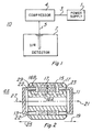
- FIG 1 is a block diagram of a cooling system 10 incorporating a dual armature compressor 4.
- the dual armature compressor 4 is powered by a power supply 1 which is connected to the dual armature compressor 4 via conductors 3.
- the dual armature compressor 4 compresses a coolant such as helium and applies it via a conduit 5 to an expander 6 shaped like a cold finger that is thermally connected to an infrared detector 7.
- the cooling system described operates on what is referred to in the art as the Stirling cycle.
- the compressor 4 has a balanced linear motor design which is illustrated in a section view in Figure 2.
- the balanced linear motor has a generally cylindrical shape with a permanent magnet 15, an inner and outer iron focusing field 16A and 16B, and two identical coils end assemblies 11 and 13 with each end assembly including a coil winding.
- the permanent magnet 15 produces lines of magnetic flux 17 which follow two independent, but symmetrical magnetic flux paths through the iron focusing fields 16A and 16B, and across identical air gaps 22 at each end. Close symmetry of the magnetic flux field in each air gap 22 is assured by the mirror image geometry of the focusing fields 16A and 16B.
- Two identical coil windings, 23 and 29, operate in the air gaps 22 and are driven by a common electrical input wave form.
- the coil windings 23 and 29 may be electrically connected in parallel or in series with attention to polarity.
- voltage When voltage is applied to the coil windings 23 and 29, the current flows to generate an induced magnetic force in opposition to the force produced by magnetic flux 17 in the air gaps.
- the magnetic force sets the movable coils 11 and 13 in linear motion in the direction of arrows 21 and 27. Reversing the current direction through the coil windings 23 and 29 reverses the magnetic force and the direction of motion 19 and 25 of the coils 11 and 13.
- Complete symmetry of the magnet 15, focusing fields 16A and 16B, air gaps, coil windings 23 and 29, and the applied current result in a balanced, opposed motion of the two end assemblies 11 and 13. Also, since the permanent magnet 15 is fully enclosed by the focusing fields 16A and 16B and the air gaps 22, the entire available flux of the magnet can be focused across the air gaps 22 and the detrimental external magnetic field of the motor is minimized.
- Figure 3 is a sectional view of a closed loop cooling system 10 that utilizes the linear induction 4A drive motor with symmetric magnetic fields to drive the compressor 4.
- the end assemblies 11 and 13 are attached to identical pistons 63.
- a compression space 65 is formed between the two opposed pistons 63 and the space is ported through a transfer tube 5 to an expander 6.
- Each piston 63 is biased toward midstroke position by a set of mechanical springs 61 and 59.
- Springs 59 each represents a set of three springs equally spaced around the diameter of the end assemblies 11 and 13 which make continuous electrical contact between the identical windings 23 and 29 and the stationaly electrical contacts 67.
- Figure 4 shows a waveform 83 of the voltage that is applied to the compressor 4 from the power supply 1 when D/C power is used. It is essentially a square wave step function operating in a 360 degree cycle. It starts at a +1 and at approximately 60 degrees, point 81, drops to the zero level and then at 120 degrees, point 82, drops to a -1 level where it stays until 210 degrees, point 84 then it goes back to zero and at 300 degrees, point 86 the waveform returns to the positive 1 position. This is approximately equivalent to the sinusoidal waveform that as indicated by waveform 83.
- the expander 6 includes a mounting flange 53 for mounting of expander to the IR detector 7.
- the compressed coolant such as helium
- the compressed coolant is applied via the helium transfer tube 5 to the expander 6 where it enters a movable displacer 58 having a matrix reservoir 57.
- Matrix reservoir 57 serves as an energy storage and heat exchange device. It has an appropriate linear temperature gradient - the end in contact with expansion volume 55 is approximately at the machine's cryogenic temperature; the opposite end is approximately at the external ambient temperature. During portions of the cycle in which pressure is increasing there is a net flow of working fluid toward cold volume 55. The matrix reservoir absorbs energy from the working fluid thus precooling the fluid as it flows toward cold volume 55. As the pressure declines, the mirror image process occurs. There is a net flow of fluid toward the ambient end of the matrix reservoir. Heat exchange between the fluid and matrix extracts energy from the matrix (warming the fluid). The energy extracted during this depressurization phase is similar in magnitude to that absorbed during pressurization. The design and material selection of the matrix reservoir is well documented in the scientific literature (see, for instance, US-A-4,404,808.
Landscapes
- Engineering & Computer Science (AREA)
- Power Engineering (AREA)
- Physics & Mathematics (AREA)
- Mechanical Engineering (AREA)
- Thermal Sciences (AREA)
- General Engineering & Computer Science (AREA)
- Compressors, Vaccum Pumps And Other Relevant Systems (AREA)
- Linear Motors (AREA)
- Reciprocating, Oscillating Or Vibrating Motors (AREA)
Description
- This invention relates to a compressor having a balanced linear induction motor.
- This compressor is to be used in a cooling system for an infrared detector. US-A-4545209 discloses such a compressor wherein permanent magnets are mounted ot two moving armatures which are each surrounded by a respective stationary drive coil and connected to a respective piston. In GB-A-1,383,134 a linear induction motor is described which uses two separate permanent magnets cooperating with magnetic fields generated by electrical windings on armatures. Both structures suffer from the drawback that it is industrially unrealistic to produce permanent magnets having identical magnetic strenghts whether at the outset or after a certain operating time. The electrical windings would unavoidably be subjected to uneven forces during their reciprocating motion, thus resulting in undesirable vibrations. Due to this drawback the compressor known from this document cannot be used in a cooling system as mentioned above, where very specific requirements have to be met.
- Infrared (I/R) detectors are used for detection of infrared energy and it is usually necessary to maintain the detector at a cryogenic temperature. An example of a prior art cooling system is disclosed in US-A- 3,851,173. In the case where the infrared detector is part of a night sight, the integration of linear resonant coolers into the infrared night sight has encountered several problems. A large external magnetic field is generally emitted by the compressor motor which causes EMI problems in the infrared system. The slightest relative motion between the magnetic field and the conductors within the field induces electrical noise on the video circuit which is connected to the infrared detectors causing a degradation in the video output.
- Another problem is the vibration caused by the compressor at its resonant frequency. In infrared systems, precision optics are used that are sensitive to vibrations. This, of course, also causes degradation in the video output.
- Several schemes have been employed to minimize the effect of EMI interferences or noise from the linear compressor. Heavy shielding of the compressor to intercept the external magnetic field, extensive shielding of the video circuit, and placing the compressor more remotely from the electronics have been tried. Each of these solutions have undesirable consequences.
- One solution for reducing vibration has been to include a spring mass type harmonic balancer within the compressor. However, with a balancer any variation in the frequency of operation results in a decrease in the balancer efficiency. Also, external sources of vibration can excite undamped oscillations.
- It is therefore the object of this invention to provide a compressor having a balanced linear induction motor which operates with a minimum of vibration and with a minimum of magnetic fields external to the compressor.
- For achieving this object the compressor is provided with the features of claim 1. Further improvements and advantageous features are indicated in
claims - The invention will now be described in the specification in conjunction with the Figures in which:
- Figure 1 is a block diagram of a cooling system including a compressor according to the invention;
- Figure 2 is a sectional diagram of the dual armature linear motor according to the invention;
- Figure 3 is a sectional view of the cooling system of Figure 1;
- Figure 4 is a waveform diagram of the voltages that are used to operate the dual action linear induction motor of the compressor according to the invention; and
- Figure 5 is a waveform diagram illustrating the pressure of the dual armature linear induction motor type compressor according to the invention.
- Figure 1 is a block diagram of a
cooling system 10 incorporating adual armature compressor 4. Thedual armature compressor 4 is powered by a power supply 1 which is connected to thedual armature compressor 4 viaconductors 3. Thedual armature compressor 4 compresses a coolant such as helium and applies it via aconduit 5 to an expander 6 shaped like a cold finger that is thermally connected to an infrared detector 7. The expander 6, through the expansion of the compressed gas from thecompressor 4, cools the IR detector 7. The cooling system described operates on what is referred to in the art as the Stirling cycle. - The
compressor 4 has a balanced linear motor design which is illustrated in a section view in Figure 2. The balanced linear motor has a generally cylindrical shape with apermanent magnet 15, an inner and outeriron focusing field coils end assemblies 11 and 13 with each end assembly including a coil winding. Thepermanent magnet 15 produces lines of magnetic flux 17 which follow two independent, but symmetrical magnetic flux paths through theiron focusing fields identical air gaps 22 at each end. Close symmetry of the magnetic flux field in eachair gap 22 is assured by the mirror image geometry of thefocusing fields air gaps 22 and are driven by a common electrical input wave form. Thecoil windings coil windings movable coils 11 and 13 in linear motion in the direction ofarrows coil windings motion coils 11 and 13. Complete symmetry of themagnet 15, focusingfields coil windings end assemblies 11 and 13. Also, since thepermanent magnet 15 is fully enclosed by thefocusing fields air gaps 22, the entire available flux of the magnet can be focused across theair gaps 22 and the detrimental external magnetic field of the motor is minimized. - Figure 3 is a sectional view of a closed
loop cooling system 10 that utilizes thelinear induction 4A drive motor with symmetric magnetic fields to drive thecompressor 4. Theend assemblies 11 and 13 are attached toidentical pistons 63. Acompression space 65 is formed between the twoopposed pistons 63 and the space is ported through atransfer tube 5 to an expander 6. Eachpiston 63 is biased toward midstroke position by a set ofmechanical springs Springs 59 each represents a set of three springs equally spaced around the diameter of theend assemblies 11 and 13 which make continuous electrical contact between theidentical windings electrical contacts 67. By applying an A/C type voltage (Figure 4) to theelectrical contacts 67 which cyclically reverses the current direction through theidentical windings end assemblies 11, and 13, causing thepistons 63 to oscillate with opposed, balanced motion. When theoperating compressor 4 is presssurized with a gas, such as helium, the opposing motion of the pistons create a sinusoidal fluctuation of thecompression space 65 and the working volume pressure (Figure 5). The end assemblies 11 and 13 and consequently the pistons vibrate as a forced spring mass system; therefore, minimum electrical power is required when the frequency of the A/C power input matches the mechanical resonance of the assemblies. Complet symmetry of themotor 4A,pistons 63, andspring mechanisms end assemblies 11 and 13, thereby mutually cancelling the vibrations transmitted to the compressor housing. The result is a smooth, balanced operation of thecompressor 4 at any operating frequency. - Figure 4 shows a waveform 83 of the voltage that is applied to the
compressor 4 from the power supply 1 when D/C power is used. It is essentially a square wave step function operating in a 360 degree cycle. It starts at a +1 and at approximately 60 degrees,point 81, drops to the zero level and then at 120 degrees,point 82, drops to a -1 level where it stays until 210 degrees,point 84 then it goes back to zero and at 300 degrees,point 86 the waveform returns to the positive 1 position. This is approximately equivalent to the sinusoidal waveform that as indicated by waveform 83. - In Figure 5 the working volume pressure that is present in the
compression space 65 is represented bywaveform 87. At resonant it is a sinusoidal waveform that is essentially 90 degrees out of phase with waveform 83 of Figure 4. - Returning to Figure 3 the expander 6 includes a
mounting flange 53 for mounting of expander to the IR detector 7. The compressed coolant, such as helium, is applied via thehelium transfer tube 5 to the expander 6 where it enters amovable displacer 58 having amatrix reservoir 57. - There are a variety of methods currently employed to produce cooling by the expander. For instance, refer to US-A-3,765,187. US-A-4,543,793, US-A-4,385,499. All of these techniques may be used with the linear drive compressor described in this invention; however, the expander used in the embodiment shown includes compressed
springs spring guide 70 for guiding themoveable displacer 58. The goal is to properly phase the motion of thedisplacer 58 with the workingvolume pressure waveform 87. Notice that the reciprocating motion ofdisplacer 58 modulates thecold volume 55. It is well known that the cooling produced inexpansion volume 55 is given by:
-
Matrix reservoir 57 serves as an energy storage and heat exchange device. It has an appropriate linear temperature gradient - the end in contact withexpansion volume 55 is approximately at the machine's cryogenic temperature; the opposite end is approximately at the external ambient temperature. During portions of the cycle in which pressure is increasing there is a net flow of working fluid towardcold volume 55. The matrix reservoir absorbs energy from the working fluid thus precooling the fluid as it flows towardcold volume 55. As the pressure declines, the mirror image process occurs. There is a net flow of fluid toward the ambient end of the matrix reservoir. Heat exchange between the fluid and matrix extracts energy from the matrix (warming the fluid). The energy extracted during this depressurization phase is similar in magnitude to that absorbed during pressurization. The design and material selection of the matrix reservoir is well documented in the scientific literature (see, for instance, US-A-4,404,808.
Claims (3)
a stator having a generally cylindrical shape and first length and first mechanical axis, said stator includes inner and outer iron focusing field members (16A, 16B) spaced apart form each other and a cylindrically shaped permanent magnet (15) centered between said inner and outer iron members and having a length less than said first length to form air gaps (22) on opposing ends of said inner and outer iron member, a pair of movable armatures (11, 13) centered around said mechanical axis, each of said armatures being generally cylindrical in shape and each positioned on opposing ends of said stator and within the air gaps, said armature also including an electrical winding (23, 29) wound around said armature, said permanent magnet (15) produces two independent but symmetrical magnetic flux paths (17) through the iron focusing field members (16A, 16B), across air gaps (22) and through electrical windings (23, 29), such that when an alternating electrical signal is applied to said windings the magnetic force sets the movable armature (11, 13) and pistons (63) in balanced linear motion in opposing directions, and a pair of pistons (63), one of said pistons coupled to one of said armatures and the other of said pistons coupled to the other of said armatures to compress and expand a predetermined volume (65) located at the end of said pistons.
Applications Claiming Priority (2)
| Application Number | Priority Date | Filing Date | Title |
|---|---|---|---|
| US867850 | 1986-05-23 | ||
| US06/867,850 US4713939A (en) | 1986-05-23 | 1986-05-23 | Linear drive motor with symmetric magnetic fields for a cooling system |
Publications (3)
| Publication Number | Publication Date |
|---|---|
| EP0246468A2 EP0246468A2 (en) | 1987-11-25 |
| EP0246468A3 EP0246468A3 (en) | 1988-10-19 |
| EP0246468B1 true EP0246468B1 (en) | 1991-12-18 |
Family
ID=25350588
Family Applications (1)
| Application Number | Title | Priority Date | Filing Date |
|---|---|---|---|
| EP87106154A Expired - Lifetime EP0246468B1 (en) | 1986-05-23 | 1987-04-28 | A linear drive motor with symmetric magnetic fields for a cooling system |
Country Status (5)
| Country | Link |
|---|---|
| US (1) | US4713939A (en) |
| EP (1) | EP0246468B1 (en) |
| KR (1) | KR960009341B1 (en) |
| DE (1) | DE3775270D1 (en) |
| IL (1) | IL82565A (en) |
Families Citing this family (21)
| Publication number | Priority date | Publication date | Assignee | Title |
|---|---|---|---|---|
| US4908536A (en) * | 1985-10-30 | 1990-03-13 | Hudimac Albert A | Vibration suppressing by electrical termination impedance |
| US4862695A (en) * | 1986-11-05 | 1989-09-05 | Ice Cryogenic Engineering Ltd. | Split sterling cryogenic cooler |
| JPH076702B2 (en) * | 1987-09-04 | 1995-01-30 | 三菱電機株式会社 | Gas cycle engine |
| US4819439A (en) * | 1987-10-08 | 1989-04-11 | Helix Technology Corporation | Linear drive motor with improved dynamic absorber |
| US4798054A (en) * | 1987-10-08 | 1989-01-17 | Helix Technology Corporation | Linear drive motor with flexure bearing support |
| US4846861A (en) * | 1988-05-06 | 1989-07-11 | Hughes Aircraft Company | Cryogenic refrigerator having a regenerator with primary and secondary flow paths |
| JP2552709B2 (en) * | 1988-05-24 | 1996-11-13 | 三菱電機株式会社 | refrigerator |
| DE59000576D1 (en) * | 1990-01-18 | 1993-01-21 | Leybold Ag | COLD HEAD WITH A REFRIGERATOR WORKING AFTER THE GIFFORD / MC MAHON PRINCIPLE. |
| EP0575384B1 (en) * | 1991-03-13 | 1996-12-11 | ITT Automotive Europe GmbH | Twin-tube shock absorber |
| FR2702269B1 (en) * | 1993-03-02 | 1995-04-07 | Cryotechnologies | Chiller fitted with a cold finger of the pulsed tube type. |
| JP3175534B2 (en) * | 1995-06-05 | 2001-06-11 | ダイキン工業株式会社 | Stirling refrigerator |
| US5693991A (en) * | 1996-02-09 | 1997-12-02 | Medis El Ltd. | Synchronous twin reciprocating piston apparatus |
| US5703418A (en) * | 1996-03-22 | 1997-12-30 | Northern Magnetics, Inc. | DC cooled linear motor |
| US6129527A (en) * | 1999-04-16 | 2000-10-10 | Litton Systems, Inc. | Electrically operated linear motor with integrated flexure spring and circuit for use in reciprocating compressor |
| EP1188221B1 (en) | 1999-06-21 | 2007-05-30 | Fisher & Paykel Appliances Limited | Linear motor |
| NZ515578A (en) | 2001-11-20 | 2004-03-26 | Fisher & Paykel Appliances Ltd | Reduction of power to free piston linear motor to reduce piston overshoot |
| US6914351B2 (en) | 2003-07-02 | 2005-07-05 | Tiax Llc | Linear electrical machine for electric power generation or motive drive |
| NZ527999A (en) | 2003-09-02 | 2005-08-26 | Fisher & Paykel Appliances Ltd | Controller improvements |
| US7032400B2 (en) | 2004-03-29 | 2006-04-25 | Hussmann Corporation | Refrigeration unit having a linear compressor |
| KR100582754B1 (en) * | 2004-12-09 | 2006-05-22 | (주)코라 | Linear Motor Compressor |
| DE102009023967A1 (en) | 2009-06-05 | 2010-12-16 | Danfoss Compressors Gmbh | Stirling cooler |
Family Cites Families (8)
| Publication number | Priority date | Publication date | Assignee | Title |
|---|---|---|---|---|
| FR2135998A5 (en) * | 1972-03-08 | 1972-12-22 | Commissariat Energie Atomique | |
| US3781559A (en) * | 1972-06-19 | 1973-12-25 | Texas Instruments Inc | Variable field of view scanning system |
| US3851173A (en) * | 1973-06-25 | 1974-11-26 | Texas Instruments Inc | Thermal energy receiver |
| US4002935A (en) * | 1975-05-15 | 1977-01-11 | A. O. Smith Corporation | Reciprocating linear motor |
| GB2038949A (en) * | 1979-01-09 | 1980-07-30 | Matoba T | Compressor |
| US4545209A (en) * | 1983-01-17 | 1985-10-08 | Helix Technology Corporation | Cryogenic refrigeration system with linear drive motors |
| US4534176A (en) * | 1984-03-23 | 1985-08-13 | The United States Of America As Represented By The Secretary Of The Army | Linear resonance cryogenic cooler |
| US4610143A (en) * | 1984-12-18 | 1986-09-09 | North American Philips Corporation | Long life vibration canceller having a gas spring |
-
1986
- 1986-05-23 US US06/867,850 patent/US4713939A/en not_active Expired - Lifetime
-
1987
- 1987-04-28 EP EP87106154A patent/EP0246468B1/en not_active Expired - Lifetime
- 1987-04-28 DE DE8787106154T patent/DE3775270D1/en not_active Expired - Lifetime
- 1987-05-18 IL IL82565A patent/IL82565A/en not_active IP Right Cessation
- 1987-05-22 KR KR87005078A patent/KR960009341B1/en not_active Expired - Fee Related
Also Published As
| Publication number | Publication date |
|---|---|
| IL82565A0 (en) | 1987-11-30 |
| KR870011461A (en) | 1987-12-23 |
| DE3775270D1 (en) | 1992-01-30 |
| IL82565A (en) | 1990-08-31 |
| EP0246468A3 (en) | 1988-10-19 |
| EP0246468A2 (en) | 1987-11-25 |
| KR960009341B1 (en) | 1996-07-18 |
| US4713939A (en) | 1987-12-22 |
Similar Documents
| Publication | Publication Date | Title |
|---|---|---|
| EP0246468B1 (en) | A linear drive motor with symmetric magnetic fields for a cooling system | |
| US3991585A (en) | Cold-gas refrigerator | |
| US5231337A (en) | Vibratory acoustic compressor | |
| US3220201A (en) | Cryogenic refrigerator operating on the stirling cycle | |
| JPH0788985B2 (en) | refrigerator | |
| US7247957B2 (en) | Electromechanical transducer linear compressor and radio transmission antenna | |
| EP0500992B1 (en) | Cryogenic refrigerator | |
| JPH076702B2 (en) | Gas cycle engine | |
| US4822390A (en) | Closed cycle gas refrigerator | |
| US5177971A (en) | Refrigerator | |
| WO1990012961A1 (en) | Stirling cycle machine and compressor for use therein | |
| EP0335643B1 (en) | Gas refrigerator | |
| US3573514A (en) | Reciprocating motor with excursion multiplication | |
| US3355676A (en) | Electrodynamical oscillating device | |
| JPH03253778A (en) | Vibration isolating device for reciprocating compressor of refrigerator | |
| JPH11148736A (en) | Electromagnetic driven reciprocating mechanism | |
| JPH04143551A (en) | refrigerator | |
| JPH076701B2 (en) | Gas cycle engine | |
| JP2546081B2 (en) | Linear motor compressor | |
| JPH0579720A (en) | Refrigerator | |
| JP3175476B2 (en) | Vibrating compressor | |
| JPH05126042A (en) | Linear motor compressor | |
| JPH0689960B2 (en) | Chiller | |
| JPH04143554A (en) | Refrigerator | |
| JPH04313650A (en) | Cooler |
Legal Events
| Date | Code | Title | Description |
|---|---|---|---|
| PUAI | Public reference made under article 153(3) epc to a published international application that has entered the european phase |
Free format text: ORIGINAL CODE: 0009012 |
|
| AK | Designated contracting states |
Kind code of ref document: A2 Designated state(s): CH DE LI |
|
| PUAL | Search report despatched |
Free format text: ORIGINAL CODE: 0009013 |
|
| AK | Designated contracting states |
Kind code of ref document: A3 Designated state(s): CH DE LI |
|
| 17P | Request for examination filed |
Effective date: 19890414 |
|
| 17Q | First examination report despatched |
Effective date: 19891113 |
|
| GRAA | (expected) grant |
Free format text: ORIGINAL CODE: 0009210 |
|
| AK | Designated contracting states |
Kind code of ref document: B1 Designated state(s): CH DE LI |
|
| REF | Corresponds to: |
Ref document number: 3775270 Country of ref document: DE Date of ref document: 19920130 |
|
| PLBE | No opposition filed within time limit |
Free format text: ORIGINAL CODE: 0009261 |
|
| STAA | Information on the status of an ep patent application or granted ep patent |
Free format text: STATUS: NO OPPOSITION FILED WITHIN TIME LIMIT |
|
| 26N | No opposition filed | ||
| REG | Reference to a national code |
Ref country code: CH Ref legal event code: PUE Owner name: TEXAS INSTRUMENTS INCORPORATED TRANSFER- RAYTHEON |
|
| PGFP | Annual fee paid to national office [announced via postgrant information from national office to epo] |
Ref country code: CH Payment date: 20020430 Year of fee payment: 16 |
|
| PGFP | Annual fee paid to national office [announced via postgrant information from national office to epo] |
Ref country code: DE Payment date: 20020502 Year of fee payment: 16 |
|
| PG25 | Lapsed in a contracting state [announced via postgrant information from national office to epo] |
Ref country code: LI Free format text: LAPSE BECAUSE OF NON-PAYMENT OF DUE FEES Effective date: 20030430 Ref country code: CH Free format text: LAPSE BECAUSE OF NON-PAYMENT OF DUE FEES Effective date: 20030430 |
|
| PG25 | Lapsed in a contracting state [announced via postgrant information from national office to epo] |
Ref country code: DE Free format text: LAPSE BECAUSE OF NON-PAYMENT OF DUE FEES Effective date: 20031101 |
|
| REG | Reference to a national code |
Ref country code: CH Ref legal event code: PL |