EP0245939B1 - A process for assembling a rotary valve - Google Patents
A process for assembling a rotary valve Download PDFInfo
- Publication number
- EP0245939B1 EP0245939B1 EP19870302904 EP87302904A EP0245939B1 EP 0245939 B1 EP0245939 B1 EP 0245939B1 EP 19870302904 EP19870302904 EP 19870302904 EP 87302904 A EP87302904 A EP 87302904A EP 0245939 B1 EP0245939 B1 EP 0245939B1
- Authority
- EP
- European Patent Office
- Prior art keywords
- sleeve
- valve
- rotor
- spring component
- spring
- Prior art date
- Legal status (The legal status is an assumption and is not a legal conclusion. Google has not performed a legal analysis and makes no representation as to the accuracy of the status listed.)
- Expired - Lifetime
Links
- 238000000034 method Methods 0.000 title claims description 20
- 230000007935 neutral effect Effects 0.000 claims description 44
- 239000012530 fluid Substances 0.000 claims description 15
- 230000000694 effects Effects 0.000 claims description 11
- 238000003466 welding Methods 0.000 claims description 5
- 239000000853 adhesive Substances 0.000 claims description 4
- 230000001070 adhesive effect Effects 0.000 claims description 4
- 230000008878 coupling Effects 0.000 description 5
- 238000010168 coupling process Methods 0.000 description 5
- 238000005859 coupling reaction Methods 0.000 description 5
- 210000005069 ears Anatomy 0.000 description 5
- 238000006073 displacement reaction Methods 0.000 description 4
- 230000000295 complement effect Effects 0.000 description 2
- 238000004026 adhesive bonding Methods 0.000 description 1
- 230000002411 adverse Effects 0.000 description 1
- 238000004891 communication Methods 0.000 description 1
- 230000002093 peripheral effect Effects 0.000 description 1
Images

Classifications
-
- B—PERFORMING OPERATIONS; TRANSPORTING
- B62—LAND VEHICLES FOR TRAVELLING OTHERWISE THAN ON RAILS
- B62D—MOTOR VEHICLES; TRAILERS
- B62D5/00—Power-assisted or power-driven steering
- B62D5/06—Power-assisted or power-driven steering fluid, i.e. using a pressurised fluid for most or all the force required for steering a vehicle
- B62D5/08—Power-assisted or power-driven steering fluid, i.e. using a pressurised fluid for most or all the force required for steering a vehicle characterised by type of steering valve used
- B62D5/083—Rotary valves
-
- Y—GENERAL TAGGING OF NEW TECHNOLOGICAL DEVELOPMENTS; GENERAL TAGGING OF CROSS-SECTIONAL TECHNOLOGIES SPANNING OVER SEVERAL SECTIONS OF THE IPC; TECHNICAL SUBJECTS COVERED BY FORMER USPC CROSS-REFERENCE ART COLLECTIONS [XRACs] AND DIGESTS
- Y10—TECHNICAL SUBJECTS COVERED BY FORMER USPC
- Y10T—TECHNICAL SUBJECTS COVERED BY FORMER US CLASSIFICATION
- Y10T137/00—Fluid handling
- Y10T137/8593—Systems
- Y10T137/86493—Multi-way valve unit
- Y10T137/86574—Supply and exhaust
- Y10T137/86638—Rotary valve
- Y10T137/86646—Plug type
- Y10T137/86662—Axial and radial flow
Definitions
- the present invention relates to rotary valves and is particularly concerned with a process for assembling such a rotary valve. More particularly the invention concerns a rotary valve of the type having a sleeve member, a rotor member within the sleeve member and relative rotation between which members about an axis and from a neutral condition causes an adjustment in the valve, C-spring means circumferentially biasing the sleeve member relative to the rotor member and the assembly to said neutral condition, the C-spring means being located around the axis and having a mouth within which is located a first abutment secured relative to the rotor member and a second abutment secured relative to the sleeve member, the abutments reacting against the C-spring means in the mouth thereof to enlarge the mouth during relative rotation between the rotor and sleeve members to effect the said biasing - such a rotary valve will hereinafter be referred to as "of the type specified”.
- Rotary valves of the type specified are frequently employed in power assisted vehicle steering gears where relative rotation between the rotor and sleeve members in response to a steering input torque and from the neutral condition adjusts the valve to control the power assistance which is provided.
- the biasing of the C-spring means either independently or in combination with other spring biasing such as a torsion rod as is well known in rotary valves, causes the rotary valve to revert to its neutral condition upon removal of the input torque; an example of a rotary valve of the type specified is to be found in our British Patent Specification No. 1,603,198.
- valve is correctly set-up (sometimes referred to as "balanced") when in its neutral condition, that is to say that the spring biasing means which reacts between the rotor and sleeve members should bias those members rotationally relative to each other and to the neutral condition in which condition fluid flow, if any, through the valve should present predetermined, balanced, characteristics.
- a typical rotary valve of the type specified for a power assisted vehicle steering gear will provide open centre, open return characteristics in its neutral condition and in this condition a supply of fluid under pressure to a common inlet port of the valve should provide pressure drops which are balanced over outlet ports of the valve these ports corresponding to connections on the valve, for example, to opposite sides of a power assistance ram and to a fluid exhaust or return.
- a rotary valve which does not provide balanced characteristics in a neutral condition as aforementioned is undesirable as it will be appreciated that, particularly in a power assisted steering gear, the use of such a valve can adversely effect the characteristics of the steering gear to an unacceptable extent.
- U.S. 4,143,676 discloses a rotary valve of the type specified which is balanced by circumferential adjustment in the positioning of one of the abutments against which the C-spring means reacts by use of adjustment screws.
- a process for assembling a rotary valve having a sleeve member, a rotor member within the sleeve member and relative rotation between which members about an axis and from a neutral condition causes an adjustment in the valve, C-spring means circumferentially biasing the sleeve member relative to the rotor member and the valve to said neutral condition, the C-spring means being located around the axis and having a mouth within which is located a first abutment secured relative to the rotor member and a second abutment secured relative to the sleeve member, the abutments reacting against the C-spring means in the mouth thereof to enlarge the mouth during relative rotation between the rotor and sleeve members to effect said biasing, and which process comprises an adjustment in the location of the circumferential position of one of said abutments relative to its respective sleeve or rotor member and positioning the rotor member circumferentially relative to the sleeve member
- the rotor and sleeve members of the rotary valve will initially be assembled so that the abutments of those members will initially be located for engagement with the C-spring biasing and this initial location of the two abutments will determine a neutral condition of the valve.
- the valve can be tested by subjecting it to fluid under pressure (conveniently from an air pressure line although usually the rotary valve will be used in practice for controlling hydraulic fluid) and pressure readings taken over various ports of the valve to assess whether the valve is in a preferred neutral condition or otherwise.
- one or other (or possibly both) of the locations for the abutments is displaced circumferentially relative to its respective rotor or sleeve member (to which that location or abutment will eventually be secured) by circumferential adjustment of the spring component so that, in effect, the sleeve is rotated partially relative to the rotor until a balanced or the predetermined neutral condition for the valve is achieved.
- the respective one or both of the abutments or the locations for those abutments is secured in position relative to its respective rotor or sleeve members by securing the spring component to that respective member.
- a jig This initial adjustment of the rotor and sleeve members and effective positioning of the abutments (or the location for those abutments or the respective members) by adjustment of the spring component and the fluid pressure testing of the valve to determine the neutral condition is conveniently achieved in a jig.
- the jig will generally correspond to a housing in which the valve will be accommodated in practice but may have the facility to provide convenient access for the purpose of adjusting the spring component circumferentially relative to the respective sleeve or rotor member to which it is to be secured.
- One or other (or each) of the sleeve and rotor members can carry the spring component which component itself carries, or is intended to engage with, the abutment which is to be circumferentially displaceable in unison with the respective sleeve member or rotor member.
- the spring component is circumferentially adjustable relative to its respective sleeve member or rotor member for the purpose of positioning the circumferential location of the abutment relative to the sleeve or rotor member with which that abutment is to be circumferentially displaceable as a unit; ultimately (that is following the determination of the preferred neutral condition) the spring component is fixedly secured relative to its sleeve or rotor member for rotation in unison with that member.
- the spring component is conveniently fixedly secured relative to its respective sleeve or rotor member by a simple locking screw, rivet or a simple welding, bonding or adhesive techniques.
- the spring component is conveniently in the form of a second C-spring means which extends around the axis of the valve assembly and is spring biased into frictional engagement with its respective sleeve or rotor member but can be displaced against its biasing to permit circumferential displacement between itself and its member as the rotary valve is being set up to provide the predetermined characteristics in the neutral condition.
- the spring biasing of the second C-spring means into frictional engagement with the respective rotor or sleeve member with which it is ultimately intended to be secured provides a convenient means by which it may be ensured that the spring component is temporarily held in position on its respective member following adjustment of the valve to the desired neutral condition and until such time as the spring component can be fixedly secured to its member, for example by adhesive or welding as aforementioned.
- the first abutment which is secured for rotation with the rotor member will comprise a radial projection on the rotor member while the second abutment secured for rotation with the sleeve member will comprise an axial projection; with such an arrangement it is preferred that the radial projection is rigid with the rotor for circumferential displacement therewith and that the second abutment (or the position for the location of that abutment) is initially circumferentially adjustable relative to the sleeve member by the spring component.
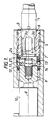
- Figure 1 is an axial section through part of a rack and pinion power assisted steering gear which incorporates one embodiment of the rotary valve
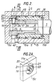
- Figure 2 is an axial section of the rotor and sleeve members incorporated in the valve in Figure 1 and which members are assembled in a jig for the purpose of determining and adjusting the characteristic of the valve in its neutral condition
- Figure 2A is a perspective view of an end cap of the jig shown in Figure 2
- Figure 3 is an end view of the sleeve member of the valve along the line III-III of Figure 2 and illustrates the adjustable spring component on that member
- Figure 4 shows a section along the line IV-IV of Figure 3
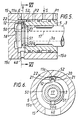
- Figure 5 is an axial section of rotor and sleeve members for a second embodiment of the rotary valve assembled in a jig similar to that shown
- the rack and pinion power assisted steering gear of which the arrangement shown in Figure 1 forms part may be considered to operate generally in accordance with conventional practice and has a steering input shaft 1 an inner end of which forms a rotor 3.
- the rotor 3 is received in a cylinder 4 of a valve sleeve 5 which latter is received in a cylinder 6 of a housing 7.
- the sleeve 5 is rotatably mounted in the cylinder 6 and is coupled to rotate in unison about axis 8 with a shaft 9 of a pinion 10 driving a rack bar (not shown) in conventional manner to effect a steering manoevre.
- the coupling between the pinion shaft 9 and the valve sleeve 5 is provided by an axially projecting spigot 11 engaging axially in a complementary sized recess 27 carried by the adjacent end of the sleeve 5.
- a pin 12 Projecting radially from the rotor 3 and in radial alignment with the projection 11 is a pin 12 secured for rotation with the rotor.
- Mounted on and extending around the rotor 3 in the radial plane of the pin 12 is a C-spring 13 having a mouth (not shown) within which is located the projection 11 and the pin 12 so that the mouth radially overlies and circumferentially opposed sides thereof abut both of these projections.
- the purpose served by the C-spring 13 is similar to that discussed in our British Patent Specification No.
- torsion bar l4 housed in a central bore l7 of the rotor to couple the pinion shaft 9 to the input shaft l and additionally serve to bias the rotor and sleeve to the neutral condition in conventional manner; however for the purpose of an understanding of the present invention, the presence of the torsion bar l4 can be disregarded.
- the rotary valve formed by the rotor 3 and sleeve 5 will usually be of the closed centre or open centre type, more commonly the open centre type of valve is employed with an open centre return in its neutral condition.
- the rotary valve is balanced with regard to the source of fluid under pressure which is applied to it so that the pressure differential between that source and outlets of the valve (say to opposite sides of a power assistance ram) are symmetrical; to achieve this it will be apparent that the position of the ports 3a in the rotor 3 must be accurately located circumferentially with respect to the ports (not shown) in the sleeve 5 with which they are to effect control of the fluid passing through the valve.
- a jig l5 (which effectively substitutes for the housing 7) which comprises a cylindrical wall 15a within which the sleeve 5 is closely received, an end wall 15b secured to wall 15a and through an aperture in which the input shaft l extends, and an end cap 15c.
- the end cap 15c has a spigot 16 which co-operates co-axially with the bore 17 in the rotor 3 so that the end cap 15c can rotate about the spigot l6 and relative to the rotor 3 and the cylinder wall 15a.
- the sleeve 5 is restrained from rotation relative to the walls 15a and 15b by pins 18.
- the end cap 15c serves as a substitute for the pinion shaft 9 in Figure 1.
- This cap has an axially extending projection 11a intended to correspond to the projection 11 in Figure l) and couples the end cap l5c to the recess 27 in the end of the sleeve 5 so that the end cap l5c and sleeve 5 can rotate in unison about the axis 8.
- the projection 11a is formed as part of a bracket 20 (see Figure 2A) on the end cap l5c.
- the bracket 20 has opposed side walls 2l which form a recess 22 radially inwardly of and in radial alignment with the projection 11a.
- the radial pin l2 of the rotor 3 is axially received in the recess 22 as a close sliding fit between the walls 2l so that the end cap l5c and rotor 3 will rotate in unison about the axis 8.
- the spring 24 has a mouth 25 formed by ears 26. Circumferentially spaced from the mouth 25, conveniently diametrically opposite thereto, is the recess 27 which is formed by circumferentially spaced and radially outwardly extending bosses 28 on the C-spring.
- the spring 24 is mounted on the end face 23 of the valve sleeve 5 within an axially extending cylindrical skirt 29 of the sleeve and so that the radially outer marginal edge part of the spring 24 is seated within an internal recess 30 of the skirt 29.
- the spring 24 is resiliently biased in a sense to circumferentially enlarge its mouth 25 so that its aforementioned marginal edge part is urged into engagement with the recess 30 as shown in Figure 4.
- the axially opposed side faces of the recess 30 converge as the depth of the recess increases (as shown in Figure 4) so that the biasing of the spring 24 urges the edge of that spring as a wedge fit into the recess 30.
- clearance is provided in the skirt 29 to accommodate the ears 26 and the outer peripheral part of the spring between the bosses 28; more particularly the skirt 29 is shown in Figure 3 cut-away at 3l to accommodate the ears 26 and cut-away at 32 to accommodate the bosses 28.
- the recess 27 in the second C-spring 24 is located on the end face of the valve sleeve 5 in axial alignment with the projection 11a of the end cap and this recess 27 axially receives the projection 11a as a reasonably close sliding fit as shown in Figure 2.
- the spring 24 may be considered as rotating in unison with the sleeve 5; from this it follows that the coupling of the end cap 15c (through the projection 11a and recess 27) with the valve sleeve 5 can cause the valve sleeve and end cap l5c to rotate in unison and that the end cap and valve sleeve could be rotated by rotation of the shaft l through the rotor 3 and radially extending pin l2.
- the characteristics of the rotary valve in its neutral condition and as they will occur in practice can be simulated in the jig 15 by the provision, in the cylinder wall 15a as shown in Figure 2, of a common fluid pressure port S, ports Pl and P2 (which may be intended for connection to opposite sides of a power assistance ram) and a common return port E (intended for communication to reservoir).
- the ports in the wall 15a will interconnect and be controlled by the rotary valve in conventional manner. It will be predetermined that if the rotary valve is in its desired neutral condition, when fluid pressure is applied to the port S there will be resultant known or balanced pressures at the ports P1, P2 and E.
- a predetermined fluid pressure is applied at port S (conveniently from an air line) and the resultant pressures at P1, P2 and E determined. If these latter pressures do not correspond to those which would be expected with the rotary valve in its neutral condition, it will be apparent that some adjustment is necessary in the relative positioning of the control ports between the sleeve and the rotor by effectively rotationally adjusting the sleeve 5 relative to the rotor 3 (and relative to the axial projection 11a bearing in mind that the engagement of the projection 11a with the sleeve 5 determines the neutral condition).
- the pressure exerted by the C-spring 24 and which frictionally secures that spring relative to the valve sleeve 5 is relieved by nipping together the ears 26 of the spring with an appropriate tool as previously discussed.
- the tool can conveniently be applied to the C-spring through an access opening 40 provided in the cylinder wall 15a. With the diameter of the C-spring 24 reduced, the spring 24 can be displaced circumferentially relative to the sleeve 5 (the latter being restrained from rotation by the pins l8) and within the extent of the cut-away region 32.
- the end cap l5c and rotor 3 are also circumferentially displaced relative to the sleeve 5 (by the engagement of the projection 11a with the recess 27 in the spring 24 and the engagement of the pin l2 with the recess 22 in radial alignment with the projection 11a).
- the control ports between the valve sleeve and valve rotor are circumferentially adjusted until the control ports are positioned in the desired neutral condition of the rotary valve (as determined by observation of the pressures at the ports P1, P2 and E).
- the rotor 3 and sleeve 5 are removed from the jig l5 without disturbing the relationship between the C-spring 24 and the valve sleeve.
- the C-spring 24 is now fixedly secured to the valve sleeve, conveniently by a laser welding technique or by adhesive bonding. Effectively the adjustment component provided by the C-spring 24 now becomes an integral part of the valve sleeve in which the recess 27 is to be coupled with the axial projection ll of the steering gear in Figure 1.
- the above described and illustrated embodiment utilises circumferential displacement of the position of the location for the coupling of the projection 11 relative to the valve sleeve for setting up the valve in its desired neutral condition.
- the rotary valve can be set-up to its desired neutral condition by having an initially fixed coupling between the projection 11a and valve sleeve 5 in the jig and providing means whereby the pin l2 can, in effect, be circumferentially displaced relative to the rotor 3 and thereafter that pin fixedly secured to the rotor when the assembly has been adjusted to its desired neutral condition.
- the projection 11a of the end cap l5c of the jig is received as a reasonably close sliding fit in a complementary recess 52 in the end face of the sleeve 5 so that the sleeve 5 is thereby restrained from rotation relative to the end cap l5c.
- the jig walls 15a and 15b are restrained from rotation relative to the end cap l5c and the C-spring 50 is restrained from rotation relative to the end cap l5c (by engagement of the projection l2 closely within the confines of the opposed side walls 2l of the bracket 20 on the end cap of the jig).
- the rotor 3 With pressure relieved on the spring 50 as previously mentioned, the rotor 3 can be circumferentially displaced relative to the pin l2 and to the sleeve 5 until the rotary valve is adjusted to its desired neutral condition as previously explained. In this latter condition the spring 50 is permitted to frictionally engage the rotor and the so adjusted rotor and sleeve are removed from the jig and the pin 12/spring 50 fixedly secured relative to the rotor 3, for example by locking screws, adhesive or welding, prior to the valve assembly being incorporated in the gear of Figure 1.
Landscapes
- Engineering & Computer Science (AREA)
- Chemical & Material Sciences (AREA)
- Combustion & Propulsion (AREA)
- Transportation (AREA)
- Mechanical Engineering (AREA)
- Power Steering Mechanism (AREA)
Description
- The present invention relates to rotary valves and is particularly concerned with a process for assembling such a rotary valve. More particularly the invention concerns a rotary valve of the type having a sleeve member, a rotor member within the sleeve member and relative rotation between which members about an axis and from a neutral condition causes an adjustment in the valve, C-spring means circumferentially biasing the sleeve member relative to the rotor member and the assembly to said neutral condition, the C-spring means being located around the axis and having a mouth within which is located a first abutment secured relative to the rotor member and a second abutment secured relative to the sleeve member, the abutments reacting against the C-spring means in the mouth thereof to enlarge the mouth during relative rotation between the rotor and sleeve members to effect the said biasing - such a rotary valve will hereinafter be referred to as "of the type specified".
- Rotary valves of the type specified are frequently employed in power assisted vehicle steering gears where relative rotation between the rotor and sleeve members in response to a steering input torque and from the neutral condition adjusts the valve to control the power assistance which is provided. The biasing of the C-spring means, either independently or in combination with other spring biasing such as a torsion rod as is well known in rotary valves, causes the rotary valve to revert to its neutral condition upon removal of the input torque; an example of a rotary valve of the type specified is to be found in our British Patent Specification No. 1,603,198.
- For efficient operation of a rotary valve of the type specified it is desirable that the valve is correctly set-up (sometimes referred to as "balanced") when in its neutral condition, that is to say that the spring biasing means which reacts between the rotor and sleeve members should bias those members rotationally relative to each other and to the neutral condition in which condition fluid flow, if any, through the valve should present predetermined, balanced, characteristics. A typical rotary valve of the type specified for a power assisted vehicle steering gear will provide open centre, open return characteristics in its neutral condition and in this condition a supply of fluid under pressure to a common inlet port of the valve should provide pressure drops which are balanced over outlet ports of the valve these ports corresponding to connections on the valve, for example, to opposite sides of a power assistance ram and to a fluid exhaust or return. A rotary valve which does not provide balanced characteristics in a neutral condition as aforementioned is undesirable as it will be appreciated that, particularly in a power assisted steering gear, the use of such a valve can adversely effect the characteristics of the steering gear to an unacceptable extent. U.S. 4,143,676 discloses a rotary valve of the type specified which is balanced by circumferential adjustment in the positioning of one of the abutments against which the C-spring means reacts by use of adjustment screws.
- It is an object of the present invention to provide a process for assembling a rotary valve of the type specified by which the characteristics of the valve in a neutral condition or the balancing of the valve can be determined to alleviate the disadvantages discussed above and in a manner which alleviates the requirement for the adjustment of screws.
- According to the present invention there is provided a process for assembling a rotary valve having a sleeve member, a rotor member within the sleeve member and relative rotation between which members about an axis and from a neutral condition causes an adjustment in the valve, C-spring means circumferentially biasing the sleeve member relative to the rotor member and the valve to said neutral condition, the C-spring means being located around the axis and having a mouth within which is located a first abutment secured relative to the rotor member and a second abutment secured relative to the sleeve member, the abutments reacting against the C-spring means in the mouth thereof to enlarge the mouth during relative rotation between the rotor and sleeve members to effect said biasing, and which process comprises an adjustment in the location of the circumferential position of one of said abutments relative to its respective sleeve or rotor member and positioning the rotor member circumferentially relative to the sleeve member to provide desired characteristics of the valve in the neutral condition, and securing the so-adjusted location relative to its respective sleeve or rotor member CHARACTERISED IN THAT said one abutment is carried to be displaced circumferentially in unison with its respective sleeve or rotor member by an adjustable spring component and the process comprises locating the spring component on the member with which said one abutment is to be circumferentially displaced in unison and with the spring component extending around the axis of the valve and biased into frictional engagement with the member on which it is located, displacing the spring component against its biasing to facilitate circumferential adjustment of the spring component on the member on which it is located in determining said adjusted location, and securing the spring component to the respective sleeve or rotor member on which it is located to rotate in unison therewith at said adjusted location.
- By the present invention it is envisaged that the rotor and sleeve members of the rotary valve will initially be assembled so that the abutments of those members will initially be located for engagement with the C-spring biasing and this initial location of the two abutments will determine a neutral condition of the valve. Following this initial assembly the valve can be tested by subjecting it to fluid under pressure (conveniently from an air pressure line although usually the rotary valve will be used in practice for controlling hydraulic fluid) and pressure readings taken over various ports of the valve to assess whether the valve is in a preferred neutral condition or otherwise. Where it is found that the valve is out of balance, one or other (or possibly both) of the locations for the abutments is displaced circumferentially relative to its respective rotor or sleeve member (to which that location or abutment will eventually be secured) by circumferential adjustment of the spring component so that, in effect, the sleeve is rotated partially relative to the rotor until a balanced or the predetermined neutral condition for the valve is achieved. In this latter condition the respective one or both of the abutments or the locations for those abutments is secured in position relative to its respective rotor or sleeve members by securing the spring component to that respective member. This initial adjustment of the rotor and sleeve members and effective positioning of the abutments (or the location for those abutments or the respective members) by adjustment of the spring component and the fluid pressure testing of the valve to determine the neutral condition is conveniently achieved in a jig. The jig will generally correspond to a housing in which the valve will be accommodated in practice but may have the facility to provide convenient access for the purpose of adjusting the spring component circumferentially relative to the respective sleeve or rotor member to which it is to be secured.
- One or other (or each) of the sleeve and rotor members can carry the spring component which component itself carries, or is intended to engage with, the abutment which is to be circumferentially displaceable in unison with the respective sleeve member or rotor member. Initially the spring component is circumferentially adjustable relative to its respective sleeve member or rotor member for the purpose of positioning the circumferential location of the abutment relative to the sleeve or rotor member with which that abutment is to be circumferentially displaceable as a unit; ultimately (that is following the determination of the preferred neutral condition) the spring component is fixedly secured relative to its sleeve or rotor member for rotation in unison with that member. Following the initial adjustment of the spring component to a position in which the valve demonstrates the desired characteristics in its neutral condition, the spring component is conveniently fixedly secured relative to its respective sleeve or rotor member by a simple locking screw, rivet or a simple welding, bonding or adhesive techniques. The spring component is conveniently in the form of a second C-spring means which extends around the axis of the valve assembly and is spring biased into frictional engagement with its respective sleeve or rotor member but can be displaced against its biasing to permit circumferential displacement between itself and its member as the rotary valve is being set up to provide the predetermined characteristics in the neutral condition. The spring biasing of the second C-spring means into frictional engagement with the respective rotor or sleeve member with which it is ultimately intended to be secured provides a convenient means by which it may be ensured that the spring component is temporarily held in position on its respective member following adjustment of the valve to the desired neutral condition and until such time as the spring component can be fixedly secured to its member, for example by adhesive or welding as aforementioned.
- Generally the first abutment which is secured for rotation with the rotor member will comprise a radial projection on the rotor member while the second abutment secured for rotation with the sleeve member will comprise an axial projection; with such an arrangement it is preferred that the radial projection is rigid with the rotor for circumferential displacement therewith and that the second abutment (or the position for the location of that abutment) is initially circumferentially adjustable relative to the sleeve member by the spring component.
- Embodiments of a rotary valve assembly of the type specified and constructed in accordance with the present invention will now be described, by way of example only, with reference to the accompanying illustrative drawings in which:
Figure 1 is an axial section through part of a rack and pinion power assisted steering gear which incorporates one embodiment of the rotary valve;
Figure 2 is an axial section of the rotor and sleeve members incorporated in the valve in Figure 1 and which members are assembled in a jig for the purpose of determining and adjusting the characteristic of the valve in its neutral condition;
Figure 2A is a perspective view of an end cap of the jig shown in Figure 2;
Figure 3 is an end view of the sleeve member of the valve along the line III-III of Figure 2 and illustrates the adjustable spring component on that member;
Figure 4 shows a section along the line IV-IV of Figure 3;
Figure 5 is an axial section of rotor and sleeve members for a second embodiment of the rotary valve assembled in a jig similar to that shown in Figure 2 but with the adjustable spring component on the rotor member for the purpose of determining and adjusting the characteristic of the valve in its neutral condition, and
Figure 6 is a section of the jig and rotary valve assembly shown in Figure 5 taken on the line VI-VI of that Figure. - The rack and pinion power assisted steering gear of which the arrangement shown in Figure 1 forms part may be considered to operate generally in accordance with conventional practice and has a
steering input shaft 1 an inner end of which forms arotor 3. Therotor 3 is received in acylinder 4 of avalve sleeve 5 which latter is received in a cylinder 6 of ahousing 7. Thesleeve 5 is rotatably mounted in the cylinder 6 and is coupled to rotate in unison aboutaxis 8 with ashaft 9 of apinion 10 driving a rack bar (not shown) in conventional manner to effect a steering manoevre. The coupling between thepinion shaft 9 and thevalve sleeve 5 is provided by an axially projecting spigot 11 engaging axially in a complementary sizedrecess 27 carried by the adjacent end of thesleeve 5. Projecting radially from therotor 3 and in radial alignment with the projection 11 is apin 12 secured for rotation with the rotor. Mounted on and extending around therotor 3 in the radial plane of thepin 12 is a C-spring 13 having a mouth (not shown) within which is located the projection 11 and thepin 12 so that the mouth radially overlies and circumferentially opposed sides thereof abut both of these projections. The purpose served by the C-spring 13 is similar to that discussed in our British Patent Specification No. 1,603,198. It will be appreciated that during relative rotation between therotor 3 and sleeve 5 (and thereby between thepin 12 and projection 11) about theaxis 8 in one or the opposite senses of direction in response to a steering input torque, the abutment of thepin 12 and projection 11 with the opposite sides of the mouth of the C-spring l3 will cause that mouth to enlarge circumferentially. The C-spring is thereby energised and this acts to bias thepin 12 and projection ll into their positions in radial alignment with each other; these latter positions correspond to therotor 3 andsleeve 5 being in a neutral condition of the rotary valve formed by these members. In the present example a conventional form of torsion bar l4 is shown housed in a central bore l7 of the rotor to couple thepinion shaft 9 to the input shaft l and additionally serve to bias the rotor and sleeve to the neutral condition in conventional manner; however for the purpose of an understanding of the present invention, the presence of the torsion bar l4 can be disregarded. - In its use in a power assisted vehicle steering gear, the rotary valve formed by the
rotor 3 andsleeve 5 will usually be of the closed centre or open centre type, more commonly the open centre type of valve is employed with an open centre return in its neutral condition. When in its neutral condition, it is desirable that the rotary valve is balanced with regard to the source of fluid under pressure which is applied to it so that the pressure differential between that source and outlets of the valve (say to opposite sides of a power assistance ram) are symmetrical; to achieve this it will be apparent that the position of theports 3a in therotor 3 must be accurately located circumferentially with respect to the ports (not shown) in thesleeve 5 with which they are to effect control of the fluid passing through the valve. This accurate location between the respective control ports must be determined bearing in mind the relative positions of thepin 12 and projection 11. An arrangement for achieving a required balancing of the rotary valve comprising themembers - Prior to incorporating the
rotor 3 and itssleeve 5 in the steering gear shown in Figure l, these members are mounted in a jig l5 (which effectively substitutes for the housing 7) which comprises acylindrical wall 15a within which thesleeve 5 is closely received, anend wall 15b secured towall 15a and through an aperture in which the input shaft l extends, and anend cap 15c. Theend cap 15c has aspigot 16 which co-operates co-axially with thebore 17 in therotor 3 so that theend cap 15c can rotate about the spigot l6 and relative to therotor 3 and thecylinder wall 15a. Thesleeve 5 is restrained from rotation relative to thewalls pins 18. In effect, theend cap 15c serves as a substitute for thepinion shaft 9 in Figure 1. This cap has an axially extendingprojection 11a intended to correspond to the projection 11 in Figure l) and couples the end cap l5c to therecess 27 in the end of thesleeve 5 so that the end cap l5c andsleeve 5 can rotate in unison about theaxis 8. Theprojection 11a is formed as part of a bracket 20 (see Figure 2A) on the end cap l5c. Thebracket 20 has opposed side walls 2l which form arecess 22 radially inwardly of and in radial alignment with theprojection 11a. On fitting theend cap 15c as part of the jig, the radial pin l2 of therotor 3 is axially received in therecess 22 as a close sliding fit between the walls 2l so that the end cap l5c androtor 3 will rotate in unison about theaxis 8. - Mounted on the
end face 23 of thesleeve 5 adjacent to the end cap l5c is an adjustment component in the form of a second C-spring 24 (best shown in Figures 3 and 4). Thespring 24 has a mouth 25 formed by ears 26. Circumferentially spaced from the mouth 25, conveniently diametrically opposite thereto, is therecess 27 which is formed by circumferentially spaced and radially outwardly extending bosses 28 on the C-spring. Thespring 24 is mounted on theend face 23 of thevalve sleeve 5 within an axially extendingcylindrical skirt 29 of the sleeve and so that the radially outer marginal edge part of thespring 24 is seated within aninternal recess 30 of theskirt 29. Thespring 24 is resiliently biased in a sense to circumferentially enlarge its mouth 25 so that its aforementioned marginal edge part is urged into engagement with therecess 30 as shown in Figure 4. Preferably the axially opposed side faces of therecess 30 converge as the depth of the recess increases (as shown in Figure 4) so that the biasing of thespring 24 urges the edge of that spring as a wedge fit into therecess 30. To permit thespring 24 to engage in therecess 30, clearance is provided in theskirt 29 to accommodate the ears 26 and the outer peripheral part of the spring between the bosses 28; more particularly theskirt 29 is shown in Figure 3 cut-away at 3l to accommodate the ears 26 and cut-away at 32 to accommodate the bosses 28. With thespring 24 mounted on theend face 23 of thesleeve 5 as aforementioned, the natural resilience of the spring urging it into frictional engagement with therecess 30 in the valve sleeve will normally, and to a limited extent, retain the C-spring against rotation about theaxis 8 relative to thevalve sleeve 5. By closing the mouth 25 of the C-spring (by nipping together the ears 26 with an appropriate tool) it will be apparent that the diameter of the C-spring is effectively reduced; the retaining pressure between the C-spring and therecess 30 can thereby be relieved to an extent that the C-spring 24 may, as determined by the circumferential clearance of the cut-awayregion 3l or 32, be partically rotated about theaxis 8 relative to thevalve sleeve 5. - The
recess 27 in the second C-spring 24 is located on the end face of thevalve sleeve 5 in axial alignment with theprojection 11a of the end cap and thisrecess 27 axially receives theprojection 11a as a reasonably close sliding fit as shown in Figure 2. Consequently, with thespring 24 frictionally secured to the sleeve 5(by the natural biasing of thespring 24 into engagement with the recess 30), thespring 24 may be considered as rotating in unison with thesleeve 5; from this it follows that the coupling of theend cap 15c (through theprojection 11a and recess 27) with thevalve sleeve 5 can cause the valve sleeve and end cap l5c to rotate in unison and that the end cap and valve sleeve could be rotated by rotation of the shaft l through therotor 3 and radially extending pin l2. - In practice the cut-away parts 3l and 32 (particularly 32) in the
skirt 29 of the valve sleeve will be positioned on that sleeve and with respect to the central ports in the sleeve (which ports co-operate with theports 3a on the rotor to effect control of the fluid) so that when the sleeve and rotor are fitted into the jig as shown in Figure 2, the circumferential orientation between the rotor and sleeve as determined by the engagement of the radial pin l2 in therecess 22 and the engagement of theaxial projection 11a in therecess 27, will approximate to the valve being in its intended neutral condition. - With the valve sleeve and rotor fitted in the jig l5 as described above, the characteristics of the rotary valve in its neutral condition and as they will occur in practice can be simulated in the
jig 15 by the provision, in thecylinder wall 15a as shown in Figure 2, of a common fluid pressure port S, ports Pl and P2 (which may be intended for connection to opposite sides of a power assistance ram) and a common return port E (intended for communication to reservoir). The ports in thewall 15a will interconnect and be controlled by the rotary valve in conventional manner. It will be predetermined that if the rotary valve is in its desired neutral condition, when fluid pressure is applied to the port S there will be resultant known or balanced pressures at the ports P1, P2 and E. Accordingly a predetermined fluid pressure is applied at port S (conveniently from an air line) and the resultant pressures at P1, P2 and E determined. If these latter pressures do not correspond to those which would be expected with the rotary valve in its neutral condition, it will be apparent that some adjustment is necessary in the relative positioning of the control ports between the sleeve and the rotor by effectively rotationally adjusting thesleeve 5 relative to the rotor 3 (and relative to theaxial projection 11a bearing in mind that the engagement of theprojection 11a with thesleeve 5 determines the neutral condition). Accordingly, to effect the aforementioned adjustment, the pressure exerted by the C-spring 24 and which frictionally secures that spring relative to thevalve sleeve 5 is relieved by nipping together the ears 26 of the spring with an appropriate tool as previously discussed. The tool can conveniently be applied to the C-spring through an access opening 40 provided in thecylinder wall 15a. With the diameter of the C-spring 24 reduced, thespring 24 can be displaced circumferentially relative to the sleeve 5 (the latter being restrained from rotation by the pins l8) and within the extent of the cut-awayregion 32. During this circumferential displacement of thespring 24 relative to thesleeve 5, the end cap l5c androtor 3 are also circumferentially displaced relative to the sleeve 5 (by the engagement of theprojection 11a with therecess 27 in thespring 24 and the engagement of the pin l2 with therecess 22 in radial alignment with theprojection 11a). As a consequence, the control ports between the valve sleeve and valve rotor are circumferentially adjusted until the control ports are positioned in the desired neutral condition of the rotary valve (as determined by observation of the pressures at the ports P1, P2 and E). With the valve so adjusted to its predetermined neutral condition, the restraint on the C-spring 24 is removed to allow that spring to expand under its natural resilience into frictional engagement with therecess 30; this effectively retains thespring 24 on thevalve sleeve 5 with therecess 27 of the spring accurately located at a position in which it engages with the projection 13a (and will therefore engage with the axial projection 11 in the steering gear assembly of Figure l) with the valve and sleeve members in their desired neutral condition. - Having so adjusted the rotary valve, the
rotor 3 andsleeve 5 are removed from the jig l5 without disturbing the relationship between the C-spring 24 and the valve sleeve. The C-spring 24 is now fixedly secured to the valve sleeve, conveniently by a laser welding technique or by adhesive bonding. Effectively the adjustment component provided by the C-spring 24 now becomes an integral part of the valve sleeve in which therecess 27 is to be coupled with the axial projection ll of the steering gear in Figure 1. Consequently when the sleeve an d rotor of the valve assembly are incorporated in the power assisted steering gear shown in Figure l with the projection 11 axially received in therecess 27 to provide the coupling between thepinion shaft 9 and the sleeve 5 (while the C-spring l3 biases the pin l2 and projection 11 into radial alignment) it will be known that the rotary valve is in its desired neutral condition. - The above described and illustrated embodiment utilises circumferential displacement of the position of the location for the coupling of the projection 11 relative to the valve sleeve for setting up the valve in its desired neutral condition. However, in a second embodiment the rotary valve can be set-up to its desired neutral condition by having an initially fixed coupling between the
projection 11a andvalve sleeve 5 in the jig and providing means whereby the pin l2 can, in effect, be circumferentially displaced relative to therotor 3 and thereafter that pin fixedly secured to the rotor when the assembly has been adjusted to its desired neutral condition. - Such a second embodiment will now be described with reference to Figures 5 and 6 in which the pin l2 is carried by (preferably an integral part of) a C-
spring 50 which encircles therotor 3 and is received in an annular recess 5l in the rotor. Thespring 50 is normally biased into frictional engagement with therotor 3 in the recess 5l but can be displaced against its biasing to diametrically enlarge the spring by opening the mouth of the spring with an appropriate tool (not shown) applied to the opposed ends 50a of the spring - the aforementioned tool is conveniently applied through theopening 40 in the jig wall as previously discussed. By relieving pressure on thespring 50, therotor 3 can be circumferentially displaced relative to the pin l2. In this second embodiment theprojection 11a of the end cap l5c of the jig is received as a reasonably close sliding fit in acomplementary recess 52 in the end face of thesleeve 5 so that thesleeve 5 is thereby restrained from rotation relative to the end cap l5c. In addition thejig walls spring 50 is restrained from rotation relative to the end cap l5c (by engagement of the projection l2 closely within the confines of the opposed side walls 2l of thebracket 20 on the end cap of the jig). With pressure relieved on thespring 50 as previously mentioned, therotor 3 can be circumferentially displaced relative to the pin l2 and to thesleeve 5 until the rotary valve is adjusted to its desired neutral condition as previously explained. In this latter condition thespring 50 is permitted to frictionally engage the rotor and the so adjusted rotor and sleeve are removed from the jig and thepin 12/spring 50 fixedly secured relative to therotor 3, for example by locking screws, adhesive or welding, prior to the valve assembly being incorporated in the gear of Figure 1.
Claims (10)
- A process for assembling a rotary valve having a sleeve member (5), a rotor member (3) within the sleeve member (5) and relative rotation between which members about an axis (8) and from a neutral condition causes an adjustment in the valve, C-spring means (13) circumferentially biasing the sleeve member (5) relative to the rotor member (3) and the valve to said neutral condition, the C-spring means (13) being located around the axis (8) and having a mouth within which is located a first abutment (12) secured relative to the rotor member (3) and a second abutment (11) secured relative to the sleeve member (5), the abutments (11,12) reacting against the C-spring means (13) in the mouth thereof to enlarge the mouth during relative rotation between the rotor and sleeve members to effect said biasing, and which process comprises an adjustment in the location of the circumferential position of one of said abutments (11, 12) relative to its respective sleeve or rotor member (5, 3) and positioning the rotor member (3) circumferentially relative to the sleeve member (5) to provide desired characteristics of the valve in the neutral condition, and securing the so-adjusted location relative to its respective sleeve or rotor member (5, 3) CHARACTERISED IN THAT said one abutment (11,12) is carried to be displaced circumferentially in unison with its respective sleeve or rotor member by an adjustable spring component (24) and the process comprises locating the spring component (24) on the member (3, 5) with which said one abutment is to be circumferentially displaced in unison and with the spring component (24) extending around the axis of the valve and biased into frictional engagement with the member on which it is located, displacing the spring component (24) against its biasing to facilitate circumferential adjustment of the spring component on the member on which it is located in determining said adjusted location, and securing the spring component (24) to the respective sleeve or rotor member (5, 3) on which it is located to rotate in unison therewith at said adjusted location.
- A process as claimed in claim 1 in which the adjustable spring component comprises second C-spring means (24) and which comprises locating the second C-spring means to frictionally engage radially in a circumferential recess (30) in the sleeve or rotor member by which it is carried.
- A process as claimed in either claim 1 or claim 2 in which said one abutment comprises a projection (11) and the adjustable spring component (24) comprises means (27) which engages with said projection (11) to rotate in unison therewith.
- A process as claimed in claim 3 in which the means which engages the said projection (11) comprises a location recess (27) in the adjustable spring component (24) within which the projection (11) is closely received.
- A process as claimed in either claim 3 or claim 4 in which the second abutment comprises an axially extending projection (11) and said projection engages with the location means (27) on the adjustable spring component (24) for rotation in unison therewith and with the sleeve member (5).
- A process as claimed in either claim 1 or claim 2 in which said one abutment comprises a projection (12) and said projection is carried by the adjustable spring component (50).
- A process as claimed in claim 6 in which the first abutment comprises a radially extending projection (12) carried by the adjustable spring component (50) for rotation in unison with the rotor member (3).
- A process as claimed in any one of the preceding claims which comprises securing the spring component (24) to the respective sleeve or rotor member on which it is located to rotate in unison therewith by at least one of locking screw means, rivetting, welding, bonding or adhesive.
- A process as claimed in any one of the preceding claims which comprises locating the valve in a jig (15) which provides a housing for the sleeve and rotor members (5, 3) and provides access to the spring component (24) for facilitating the circumferential adjustment of that component relative to the respective sleeve or rotor member on which it is located.
- A process as claimed in claim 9 which comprises subjecting the valve in the jig (15) to fluid pressure and determining fluid pressure characteristics at ports (P1, P2) of the valve, and circumferentially adjusting the spring component (24) for said fluid pressure characteristics to be consistent with the valve being in its neutral condition and securing the spring component (24) to the respective sleeve or rotor member (5, 3) on which it is located to rotate in unison therewith at the adjusted position.
Applications Claiming Priority (2)
| Application Number | Priority Date | Filing Date | Title |
|---|---|---|---|
| GB8609018A GB2188888B (en) | 1986-04-14 | 1986-04-14 | A rotary valve assembly and a method of assembling a rotary valve |
| GB8609018 | 1986-04-14 |
Publications (3)
| Publication Number | Publication Date |
|---|---|
| EP0245939A2 EP0245939A2 (en) | 1987-11-19 |
| EP0245939A3 EP0245939A3 (en) | 1988-05-25 |
| EP0245939B1 true EP0245939B1 (en) | 1991-07-03 |
Family
ID=10596139
Family Applications (1)
| Application Number | Title | Priority Date | Filing Date |
|---|---|---|---|
| EP19870302904 Expired - Lifetime EP0245939B1 (en) | 1986-04-14 | 1987-04-02 | A process for assembling a rotary valve |
Country Status (7)
| Country | Link |
|---|---|
| US (1) | US4823839A (en) |
| EP (1) | EP0245939B1 (en) |
| JP (1) | JPS62295775A (en) |
| KR (1) | KR930006509B1 (en) |
| BR (1) | BR8701755A (en) |
| DE (1) | DE3771122D1 (en) |
| GB (1) | GB2188888B (en) |
Families Citing this family (11)
| Publication number | Priority date | Publication date | Assignee | Title |
|---|---|---|---|---|
| JPH0736868Y2 (en) * | 1990-03-20 | 1995-08-23 | ティーアールダブリュエスアイ株式会社 | Valve assembly structure in power steering system |
| US5230273A (en) * | 1990-07-25 | 1993-07-27 | Trw Inc. | Apparatus for controlling fluid flow to a power steering actuator |
| US5427134A (en) * | 1991-10-29 | 1995-06-27 | James N. Kirby Products Pty Limited | Rotary valve for hydraulic power steering |
| US5316043A (en) * | 1992-02-04 | 1994-05-31 | Techco Corporation | Preload mechanism for power steering apparatus |
| US5311906A (en) * | 1992-02-04 | 1994-05-17 | Techco Corporation | Preload mechanism for power steering apparatus |
| DE4319131A1 (en) * | 1993-06-09 | 1994-12-15 | Trw Fahrwerksyst Gmbh & Co | Method and device for adjusting the hydraulic neutral position of a servo valve |
| DE4330159C1 (en) * | 1993-09-07 | 1994-11-10 | Trw Fahrwerksyst Gmbh & Co | Steering valve with a sealed centre |
| US5727443A (en) * | 1994-11-28 | 1998-03-17 | A.E. Bishop & Associates Pty Limited | Method of balancing a hydraulic valve for a power steering gear |
| DE19853142A1 (en) * | 1998-11-18 | 2000-05-25 | Zahnradfabrik Friedrichshafen | Method for mounting a rotary slide valve for power steering systems, in particular for motor vehicles |
| CN101700618B (en) * | 2009-10-22 | 2011-06-22 | 天津银河阀门有限公司 | Hydraulic pressure butterfly valve shaft sleeve installation machine and installation method |
| EP3585675B1 (en) | 2017-02-23 | 2021-03-24 | China Automotive Systems, Inc. | A control assembly for power steering |
Family Cites Families (12)
| Publication number | Priority date | Publication date | Assignee | Title |
|---|---|---|---|---|
| US3145626A (en) * | 1961-09-18 | 1964-08-25 | Bendix Corp | Power steering mechanism |
| US3296939A (en) * | 1962-09-24 | 1967-01-10 | Bendix Corp | Power steering mechanism |
| GB1030277A (en) * | 1964-04-06 | 1966-05-18 | Burman & Sons Ltd | Hydraulically operated vehicle steering mechanisms |
| US4143676A (en) * | 1976-03-29 | 1979-03-13 | Jozsef Ivony | Hydraulic port control apparatus, e.g. for motor vehicle servo steering gear |
| US4177714A (en) * | 1977-10-25 | 1979-12-11 | General Motors Corporation | Torsion bar for power steering gear |
| GB1603198A (en) * | 1978-04-10 | 1981-11-18 | Cam Gears Ltd | Powerassisted steering |
| JPS5715065A (en) * | 1980-06-27 | 1982-01-26 | Koyo Seiko Co Ltd | Spring reaction force device in power steering device |
| JPS57107958A (en) * | 1980-12-24 | 1982-07-05 | Jidosha Kiki Co Ltd | Detective method and equipment for displacement from neutral state position of power steering device |
| EP0067572B1 (en) * | 1981-06-03 | 1987-08-19 | Trw Cam Gears Limited | A power assisted steering gear assembly |
| GB2109757B (en) * | 1981-11-18 | 1985-06-19 | Cam Gears Ltd | A power assisted steering gear |
| GB2165502B (en) * | 1984-10-12 | 1987-10-14 | Trw Cam Gears Ltd | A power-assisted steering gear |
| GB2179606B (en) * | 1985-08-26 | 1988-06-15 | Bishop Arthur E | Power steering gear adjusting mechanism |
-
1986
- 1986-04-14 GB GB8609018A patent/GB2188888B/en not_active Expired
-
1987
- 1987-04-02 DE DE8787302904T patent/DE3771122D1/en not_active Expired - Lifetime
- 1987-04-02 EP EP19870302904 patent/EP0245939B1/en not_active Expired - Lifetime
- 1987-04-13 KR KR1019870003575A patent/KR930006509B1/en not_active Expired - Fee Related
- 1987-04-13 BR BR8701755A patent/BR8701755A/en not_active IP Right Cessation
- 1987-04-13 JP JP62090610A patent/JPS62295775A/en active Pending
- 1987-04-13 US US07/037,808 patent/US4823839A/en not_active Expired - Fee Related
Also Published As
| Publication number | Publication date |
|---|---|
| GB2188888B (en) | 1989-12-06 |
| US4823839A (en) | 1989-04-25 |
| EP0245939A2 (en) | 1987-11-19 |
| KR930006509B1 (en) | 1993-07-16 |
| KR870010346A (en) | 1987-11-30 |
| BR8701755A (en) | 1988-01-12 |
| GB2188888A (en) | 1987-10-14 |
| JPS62295775A (en) | 1987-12-23 |
| GB8609018D0 (en) | 1986-05-21 |
| EP0245939A3 (en) | 1988-05-25 |
| DE3771122D1 (en) | 1991-08-08 |
Similar Documents
| Publication | Publication Date | Title |
|---|---|---|
| EP0245939B1 (en) | A process for assembling a rotary valve | |
| US4966192A (en) | Rotary directional control valve | |
| US4194531A (en) | Rotary valves | |
| US4429621A (en) | Hydraulic systems | |
| US4996905A (en) | Rack and pinion steering system | |
| US3404704A (en) | Power-steering valve | |
| KR0139706B1 (en) | Rotary valve for hydraulic power steering | |
| JP2000344119A (en) | Pressure shutoff device for power steering device at stationary steering end position | |
| AU643631B2 (en) | Power steering-gear permitting separate mechanical and hydraulic balancing | |
| US5131486A (en) | Power steering control valve mechanism | |
| JPH0629036B2 (en) | Control device for static steering means | |
| JP3973243B2 (en) | Hydraulic control valve | |
| GB2199000A (en) | A valve assembly for a power assisted steering system | |
| US4186774A (en) | Hydraulic control device | |
| JPH0117496Y2 (en) | ||
| JP2589451Y2 (en) | Hydraulic power steering device | |
| JPH036544Y2 (en) | ||
| JPH051196B2 (en) | ||
| JPH1016803A (en) | Steering force adjustment device | |
| JPH06278624A (en) | Servo valve | |
| JPS6216390Y2 (en) | ||
| JP2515118Y2 (en) | Full hydraulic power steering device with input detection device | |
| WO1999011503A1 (en) | Power steering valves | |
| JPH092307A (en) | Hydraulic power-steering device | |
| JPS6220950B2 (en) |
Legal Events
| Date | Code | Title | Description |
|---|---|---|---|
| PUAI | Public reference made under article 153(3) epc to a published international application that has entered the european phase |
Free format text: ORIGINAL CODE: 0009012 |
|
| AK | Designated contracting states |
Kind code of ref document: A2 Designated state(s): DE FR GB IT |
|
| PUAL | Search report despatched |
Free format text: ORIGINAL CODE: 0009013 |
|
| AK | Designated contracting states |
Kind code of ref document: A3 Designated state(s): DE FR GB IT |
|
| RHK1 | Main classification (correction) |
Ipc: B62D 5/083 |
|
| 17P | Request for examination filed |
Effective date: 19880516 |
|
| 17Q | First examination report despatched |
Effective date: 19890517 |
|
| GRAA | (expected) grant |
Free format text: ORIGINAL CODE: 0009210 |
|
| ITF | It: translation for a ep patent filed | ||
| AK | Designated contracting states |
Kind code of ref document: B1 Designated state(s): DE FR GB IT |
|
| REF | Corresponds to: |
Ref document number: 3771122 Country of ref document: DE Date of ref document: 19910808 |
|
| ET | Fr: translation filed | ||
| PLBE | No opposition filed within time limit |
Free format text: ORIGINAL CODE: 0009261 |
|
| STAA | Information on the status of an ep patent application or granted ep patent |
Free format text: STATUS: NO OPPOSITION FILED WITHIN TIME LIMIT |
|
| 26N | No opposition filed | ||
| PGFP | Annual fee paid to national office [announced via postgrant information from national office to epo] |
Ref country code: FR Payment date: 19970625 Year of fee payment: 11 |
|
| PG25 | Lapsed in a contracting state [announced via postgrant information from national office to epo] |
Ref country code: FR Free format text: THE PATENT HAS BEEN ANNULLED BY A DECISION OF A NATIONAL AUTHORITY Effective date: 19980430 |
|
| REG | Reference to a national code |
Ref country code: FR Ref legal event code: ST |
|
| PGFP | Annual fee paid to national office [announced via postgrant information from national office to epo] |
Ref country code: GB Payment date: 20010313 Year of fee payment: 15 |
|
| PGFP | Annual fee paid to national office [announced via postgrant information from national office to epo] |
Ref country code: DE Payment date: 20010430 Year of fee payment: 15 |
|
| REG | Reference to a national code |
Ref country code: GB Ref legal event code: IF02 |
|
| PG25 | Lapsed in a contracting state [announced via postgrant information from national office to epo] |
Ref country code: GB Free format text: LAPSE BECAUSE OF NON-PAYMENT OF DUE FEES Effective date: 20020402 |
|
| PG25 | Lapsed in a contracting state [announced via postgrant information from national office to epo] |
Ref country code: DE Free format text: LAPSE BECAUSE OF NON-PAYMENT OF DUE FEES Effective date: 20021101 |
|
| GBPC | Gb: european patent ceased through non-payment of renewal fee |
Effective date: 20020402 |
|
| PG25 | Lapsed in a contracting state [announced via postgrant information from national office to epo] |
Ref country code: IT Free format text: LAPSE BECAUSE OF NON-PAYMENT OF DUE FEES;WARNING: LAPSES OF ITALIAN PATENTS WITH EFFECTIVE DATE BEFORE 2007 MAY HAVE OCCURRED AT ANY TIME BEFORE 2007. THE CORRECT EFFECTIVE DATE MAY BE DIFFERENT FROM THE ONE RECORDED. Effective date: 20050402 |