EP0245816B1 - Fiber reinforced structural member - Google Patents
Fiber reinforced structural member Download PDFInfo
- Publication number
- EP0245816B1 EP0245816B1 EP87106796A EP87106796A EP0245816B1 EP 0245816 B1 EP0245816 B1 EP 0245816B1 EP 87106796 A EP87106796 A EP 87106796A EP 87106796 A EP87106796 A EP 87106796A EP 0245816 B1 EP0245816 B1 EP 0245816B1
- Authority
- EP
- European Patent Office
- Prior art keywords
- fiber reinforced
- core
- structural member
- core element
- shell element
- Prior art date
- Legal status (The legal status is an assumption and is not a legal conclusion. Google has not performed a legal analysis and makes no representation as to the accuracy of the status listed.)
- Expired - Lifetime
Links
Images

Classifications
-
- B—PERFORMING OPERATIONS; TRANSPORTING
- B29—WORKING OF PLASTICS; WORKING OF SUBSTANCES IN A PLASTIC STATE IN GENERAL
- B29D—PRODUCING PARTICULAR ARTICLES FROM PLASTICS OR FROM SUBSTANCES IN A PLASTIC STATE
- B29D99/00—Subject matter not provided for in other groups of this subclass
- B29D99/0003—Producing profiled members, e.g. beams
- B29D99/0007—Producing profiled members, e.g. beams having a variable cross-section
-
- B—PERFORMING OPERATIONS; TRANSPORTING
- B61—RAILWAYS
- B61F—RAIL VEHICLE SUSPENSIONS, e.g. UNDERFRAMES, BOGIES OR ARRANGEMENTS OF WHEEL AXLES; RAIL VEHICLES FOR USE ON TRACKS OF DIFFERENT WIDTH; PREVENTING DERAILING OF RAIL VEHICLES; WHEEL GUARDS, OBSTRUCTION REMOVERS OR THE LIKE FOR RAIL VEHICLES
- B61F5/00—Constructional details of bogies; Connections between bogies and vehicle underframes; Arrangements or devices for adjusting or allowing self-adjustment of wheel axles or bogies when rounding curves
- B61F5/50—Other details
- B61F5/52—Bogie frames
- B61F5/523—Bogie frames comprising parts made from fibre-reinforced matrix material
-
- Y—GENERAL TAGGING OF NEW TECHNOLOGICAL DEVELOPMENTS; GENERAL TAGGING OF CROSS-SECTIONAL TECHNOLOGIES SPANNING OVER SEVERAL SECTIONS OF THE IPC; TECHNICAL SUBJECTS COVERED BY FORMER USPC CROSS-REFERENCE ART COLLECTIONS [XRACs] AND DIGESTS
- Y02—TECHNOLOGIES OR APPLICATIONS FOR MITIGATION OR ADAPTATION AGAINST CLIMATE CHANGE
- Y02T—CLIMATE CHANGE MITIGATION TECHNOLOGIES RELATED TO TRANSPORTATION
- Y02T30/00—Transportation of goods or passengers via railways, e.g. energy recovery or reducing air resistance
-
- Y—GENERAL TAGGING OF NEW TECHNOLOGICAL DEVELOPMENTS; GENERAL TAGGING OF CROSS-SECTIONAL TECHNOLOGIES SPANNING OVER SEVERAL SECTIONS OF THE IPC; TECHNICAL SUBJECTS COVERED BY FORMER USPC CROSS-REFERENCE ART COLLECTIONS [XRACs] AND DIGESTS
- Y10—TECHNICAL SUBJECTS COVERED BY FORMER USPC
- Y10S—TECHNICAL SUBJECTS COVERED BY FORMER USPC CROSS-REFERENCE ART COLLECTIONS [XRACs] AND DIGESTS
- Y10S52/00—Static structures, e.g. buildings
- Y10S52/07—Synthetic building materials, reinforcements and equivalents
-
- Y—GENERAL TAGGING OF NEW TECHNOLOGICAL DEVELOPMENTS; GENERAL TAGGING OF CROSS-SECTIONAL TECHNOLOGIES SPANNING OVER SEVERAL SECTIONS OF THE IPC; TECHNICAL SUBJECTS COVERED BY FORMER USPC CROSS-REFERENCE ART COLLECTIONS [XRACs] AND DIGESTS
- Y10—TECHNICAL SUBJECTS COVERED BY FORMER USPC
- Y10S—TECHNICAL SUBJECTS COVERED BY FORMER USPC CROSS-REFERENCE ART COLLECTIONS [XRACs] AND DIGESTS
- Y10S52/00—Static structures, e.g. buildings
- Y10S52/08—Imitation beams
-
- Y—GENERAL TAGGING OF NEW TECHNOLOGICAL DEVELOPMENTS; GENERAL TAGGING OF CROSS-SECTIONAL TECHNOLOGIES SPANNING OVER SEVERAL SECTIONS OF THE IPC; TECHNICAL SUBJECTS COVERED BY FORMER USPC CROSS-REFERENCE ART COLLECTIONS [XRACs] AND DIGESTS
- Y10—TECHNICAL SUBJECTS COVERED BY FORMER USPC
- Y10T—TECHNICAL SUBJECTS COVERED BY FORMER US CLASSIFICATION
- Y10T428/00—Stock material or miscellaneous articles
- Y10T428/23—Sheet including cover or casing
- Y10T428/233—Foamed or expanded material encased
-
- Y—GENERAL TAGGING OF NEW TECHNOLOGICAL DEVELOPMENTS; GENERAL TAGGING OF CROSS-SECTIONAL TECHNOLOGIES SPANNING OVER SEVERAL SECTIONS OF THE IPC; TECHNICAL SUBJECTS COVERED BY FORMER USPC CROSS-REFERENCE ART COLLECTIONS [XRACs] AND DIGESTS
- Y10—TECHNICAL SUBJECTS COVERED BY FORMER USPC
- Y10T—TECHNICAL SUBJECTS COVERED BY FORMER US CLASSIFICATION
- Y10T428/00—Stock material or miscellaneous articles
- Y10T428/23—Sheet including cover or casing
- Y10T428/234—Sheet including cover or casing including elements cooperating to form cells
Definitions
- the present invention relates to a fiber reinforced structural member, i.e. a lightweight structural member having a sufficient rigidity and strength.
- Fiber reinforced plastics are well-known fiber reinforced materials.
- Various fibers including glass fibers and carbon fibers have been developed for use in FRPs. These fibers have a strength equivalent to or greater than those of steels.
- FRP structural members are capable of replacing reliable steel structural meters and various FRPs have been applied to structural members for supporting load.
- Fig. 1 shows a beam member, an exemplary structural member to which the present invention pertains, comprising an elongate beam body 1 formed of a FRP, bearing pads 2 and 3 attached to the opposite ends of the beam body 1, respectively, and a load bearing part 4 provided at the middle of the beam body 1 for bearing an external load.
- the beam body 1 supported at the opposite ends thereof is loaded in the middle portion thereof, the bending moment is large in the middle portion and small at the end portions.
- the elastic modulus or such a fiber reinforced plastic structural member is 1/20 to 1/5 that of steels, ordinarily, the beam body 1, namely, the structural member, is provided with an internal reinforcement to uniformize the bending stress in the section thereof.
- Fig. 6 illustrates an exemplary conventional structural member provided with an internal reinforcement.
- This structural member comprises a beam body 1 having a rectangular cross section, a reinforcing plate 5 formed of the same material as the beam body 1 and provided inside the beam member 1, and a filling material 6 such as, for example, foam polyurethane, filling the inner space of the beam body 1.
- a filling material 6 such as, for example, foam polyurethane
- a fiber reinforced structural member comprising a shell element formed of a fiber reinforced material and having a closed cross-section; and a core member having two side faces fixedly joined to inner surface sides of said shell element wherein said core member comprises one core element having a closed cross-section internally filled with a filler material and wherein the interior of said shell element except that of said core element is filled with filling or core strips which are attached to the outer surface of said core member.
- It is another object of the present invention to provide a fiber reinforced structural member comprising a shell element, and a core element or elements having a large joining area joined to the shell element so that the junctions of the shell element and the core element or elements are strong enough to withstand tensile force and shearing force which act on the junctions.
- the fiber reinforced structural member comprises features according to claim 1 and is further embodied by features of claim 2.
- the fiber reinforced structural member comprises features of claim 3.
- a fiber reinforced structural member A comprises a shell element 13a having a closed cross section and formed of a fiber reinforced material such as, for example, a FRP, and a core element a2 provided inside the shell element 13a in surface contact an fixedly joined over the entire contact surface thereof to the shell element 13a.
- the core element a2 comprises two primary core elements a1 each formed by filling a filling material 12a such as, for example, foam polyurethane, in a hollow elongate core member 11a having a rectangular cross section and formed of a fiber reinforced material such as, for example, a FRP.
- the two primary core elements a1 are united together to form the core element a2.
- Gaps formed between the outer surface of the core element a2 and the inner surface of the shell element 13a are filled with the same resin 14 as that of the FRP forming the shell element 13a.
- the resin is applied to the outer surface of the core element a2 before inserting the core element a2 into the shell element 13a.
- the second embodiment is similar to the first embodiment in construction.
- a core element a2 is constructed by uniting three primary core elements a1, which are the same in construction as the primary core elements a1 of the first embodiment.
- a fiber reinforced structural member B in a third embodiment, according to the present invention comprises: a shell element 13b formed of a fiber reinforced material such as, for example, a FRP, and having a closed cross section; and a core element b2 constructed by uniting, in a back-to-back fashion, two primary core elements b1 each formed by filling a filling material 12a such as, for example, foam polyurethane, in an elongate channel-shaped core member 11b.
- the shell element 13b and the core element b2 are joined fixedly over the entire contact surfaces thereof.
- a fiber reinforced structural member D in a fourth embodiment, according to the present invention comprises: a shell element 13d formed of a fiber reinforced material such as, for example, a FRP, and having a closed cross section; and a core element d2 comprising a primary core element d1 formed by filling a filling material 12d such as, for example, foam polyurethane, in a channel-shaped elongate core member 11d formed of a fiber reinforced material, and a core strip 15d formed of a synthetic resin such as, for example, foam polyurethane, and attached to the outer surface of the bottom wall of the channel-shaped elongate core member 11d.
- the core element d2 is inserted in the shell element 13d, and then the core element d2 and the shell element 13d are joined fixedly over the entire contact surface thereof to form the fiber reinforced structural member D.
Landscapes
- Engineering & Computer Science (AREA)
- Mechanical Engineering (AREA)
- Rod-Shaped Construction Members (AREA)
- Moulding By Coating Moulds (AREA)
- Laminated Bodies (AREA)
Description
- The present invention relates to a fiber reinforced structural member, i.e. a lightweight structural member having a sufficient rigidity and strength.
- Fiber reinforced plastics (hereinafter abbreviated to "FRPs") are well-known fiber reinforced materials. Various fibers including glass fibers and carbon fibers have been developed for use in FRPs. These fibers have a strength equivalent to or greater than those of steels. Thus, FRP structural members are capable of replacing reliable steel structural meters and various FRPs have been applied to structural members for supporting load.
- On the other hand, since the specific gravity of FRPs, in general, is on the order of one-fifth the specific gravity of steels, the application of FRP structural members to constructing structures reduces the total weight of the structures effectively.
- Fig. 1 shows a beam member, an exemplary structural member to which the present invention pertains, comprising an
elongate beam body 1 formed of a FRP,bearing pads beam body 1, respectively, and aload bearing part 4 provided at the middle of thebeam body 1 for bearing an external load. When thebeam body 1 supported at the opposite ends thereof is loaded in the middle portion thereof, the bending moment is large in the middle portion and small at the end portions. Since the elastic modulus or such a fiber reinforced plastic structural member is 1/20 to 1/5 that of steels, ordinarily, thebeam body 1, namely, the structural member, is provided with an internal reinforcement to uniformize the bending stress in the section thereof. - Fig. 6 illustrates an exemplary conventional structural member provided with an internal reinforcement. This structural member comprises a
beam body 1 having a rectangular cross section, areinforcing plate 5 formed of the same material as thebeam body 1 and provided inside thebeam member 1, and afilling material 6 such as, for example, foam polyurethane, filling the inner space of thebeam body 1. In this structural member, however, since thereinforcing plate 5 is joined along the narrow side edges thereof to the inner surface of thebeam body 1, the strength of the junctions is not large enough to withstand tensile force and shearing force which act on the junctions, and hence such a conventional structural member is not satisfactory in reliability. - From the document THE ENGINEER, vol. 231, no. 5979, 27th August 1970, page 7; "Fibre build big blades" a fiber reinforced structural member is known, comprising a shell element formed of a fiber reinforced material and having a closed cross-section; and a core member having two side faces fixedly joined to inner surface sides of said shell element wherein said core member comprises one core element having a closed cross-section internally filled with a filler material and wherein the interior of said shell element except that of said core element is filled with filling or core strips which are attached to the outer surface of said core member.
- It is an object of the present invention to provide a fiber reinforced structural member formed of a fiber reinforced material having many advantages as mentioned above and eliminated of the drawbacks of the conventional fiber reinforced structural member through the application of simple and rational means.
- It is another object of the present invention to provide a fiber reinforced structural member comprising a shell element, and a core element or elements having a large joining area joined to the shell element so that the junctions of the shell element and the core element or elements are strong enough to withstand tensile force and shearing force which act on the junctions.
- In one aspect of the present invention the fiber reinforced structural member comprises features according to
claim 1 and is further embodied by features ofclaim 2. - In another aspect of the present invention the fiber reinforced structural member comprises features of
claim 3. - With regard to the reference THE ENGINEER the obvious differences of the claimed new fiber reinforced structural members are as follows:
- I) The core element a₂ is fixedly joined to the entire inner surface of the
shell element 13a (see embodiments of Figs. 2 and 3). - II) The core element a₂ or b₂ is formed by at least two primary core elements a₁ or b₁, see embodiments shown in Figs. 2 to 4.
- III) The primary core elements a₁ or b₁ are fixed together and supplemented in view of the external slot by a
resin 14, see embodiments shown in Figs. 2 to 4, which further enhances the reinforcement of the structural member and contributes to advantages in distribution of external forces applied thereto. - IV) There are additional filling or
core strips 15a or 15b with the embodiments shown in Figs. 5 and 6, which are fixed at the opposite side or at the bottom of thecore members 11c or 11d. - The above and other objects, features and advantages of the present invention will become more apparent from the following description taken in conjunction with the accompanying drawings, in which:
- Figure 1 is a perspective view of a structural member to which the present invention pertains;
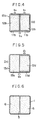
- Figures 2, 3 and 4 are sectional views of fiber reinforced structural members in first, second and third embodiments, respectively, according to the present invention;
- Figure 5 is a sectional view of a fiber reinforced structural member in a fourth embodiment, according to the present invention; and
- Figure 6 is a sectional view of a conventional fiber reinforced structural member.
- Referring to Fig. 2, a fiber reinforced structural member A comprises a
shell element 13a having a closed cross section and formed of a fiber reinforced material such as, for example, a FRP, and a core element a₂ provided inside theshell element 13a in surface contact an fixedly joined over the entire contact surface thereof to theshell element 13a. The core element a₂ comprises two primary core elements a₁ each formed by filling a fillingmaterial 12a such as, for example, foam polyurethane, in a hollowelongate core member 11a having a rectangular cross section and formed of a fiber reinforced material such as, for example, a FRP. The two primary core elements a₁ are united together to form the core element a₂. Gaps formed between the outer surface of the core element a₂ and the inner surface of theshell element 13a are filled with thesame resin 14 as that of the FRP forming theshell element 13a. The resin is applied to the outer surface of the core element a₂ before inserting the core element a₂ into theshell element 13a. - In Fig. 3, parts similar to those previously described with reference to Fig. 2 are denoted by the same reference characters.
- Basically, the second embodiment is similar to the first embodiment in construction. In the second embodiment, a core element a₂ is constructed by uniting three primary core elements a₁, which are the same in construction as the primary core elements a₁ of the first embodiment.
- A fiber reinforced structural member B, in a third embodiment, according to the present invention comprises: a
shell element 13b formed of a fiber reinforced material such as, for example, a FRP, and having a closed cross section; and a core element b₂ constructed by uniting, in a back-to-back fashion, two primary core elements b₁ each formed by filling a fillingmaterial 12a such as, for example, foam polyurethane, in an elongate channel-shaped core member 11b. Theshell element 13b and the core element b₂ are joined fixedly over the entire contact surfaces thereof. -
- A fiber reinforced structural member D, in a fourth embodiment, according to the present invention comprises: a
shell element 13d formed of a fiber reinforced material such as, for example, a FRP, and having a closed cross section; and a core element d₂ comprising a primary core element d₁ formed by filling afilling material 12d such as, for example, foam polyurethane, in a channel-shapedelongate core member 11d formed of a fiber reinforced material, and a core strip 15d formed of a synthetic resin such as, for example, foam polyurethane, and attached to the outer surface of the bottom wall of the channel-shapedelongate core member 11d. The core element d₂ is inserted in theshell element 13d, and then the core element d₂ and theshell element 13d are joined fixedly over the entire contact surface thereof to form the fiber reinforced structural member D. - In accordance with the present invention, there have been described fiber reinforced structural members in preferred embodiments, from which it is apparent that
- (a) the core element and the shell element are in contact with each other with a large contact surface extending over the entire inner surface of the shell element and hence an external force applied to the fiber reinforced structural member is distributed over the entire joining surface, so that stress in the joining surface is reduced and the reliability of the fiber reinforced structural member is enhanced;
- (b) the primary core element and the core strip or strips of the core element are joined over a large joining surface and an external force acting on the core element is distributed over the entire joining surface, and hence the stress in the joining surface is reduced, so that the reliability of the fiber reinforced structural member is enhanced; and
- (c) the primary core element or elements and the shell element are lightweight members formed of a fiber reinforced material such as, for example, a FRP, and hence the weight per unit strength of the fiber reinforced structural member is small, which is advantageous for the structural member.
Claims (3)
- A fiber reinforced structural member (1) comprising a shell element (13a, 13b) formed of a fiber reinforced material and having a closed cross section; and
at least one core member (11a, 11b) having two side faces fixedly joined to inner surface sides of said shell element (13a, 13b),
said at least one core member (11a, 11b) having a closed or a channel-shaped cross section and being internally filled with a filling material (12a, 12b) to form at least one primary core element (a1, b1),
said at least one primary core element (a1, b1) being fixedly joined to each other with a large contact surface to form a secondary core element (a2, b2). - A structural member according to claim 1, wherein said secondary core lement (a2) is fixedly joined to the entire inner surface of said shell element (13a).
- A fiber reinforced structural member (1) comprising:
a shell element (13d) formed of a fiber reinforced material and having a closed cross section; and
a core member (11d) having a channel-shaped cross-section internally filled with a filler (12d) to form a primary core element (d1), the interior of said shell element (13d) except that of said primary core element (d1) being filled with filler or core strips (15b) which are attached to the outer surface of said core element (d1) to form a secondary core element (d2), said secondary core element (d2) being fixedly joined to the inner surface sides of said shell element (13d).
Applications Claiming Priority (2)
| Application Number | Priority Date | Filing Date | Title |
|---|---|---|---|
| JP109308/86 | 1986-05-12 | ||
| JP61109308A JPH0777763B2 (en) | 1986-05-12 | 1986-05-12 | Beam-shaped structural members reinforced with fibers |
Publications (3)
| Publication Number | Publication Date |
|---|---|
| EP0245816A2 EP0245816A2 (en) | 1987-11-19 |
| EP0245816A3 EP0245816A3 (en) | 1989-05-10 |
| EP0245816B1 true EP0245816B1 (en) | 1994-08-03 |
Family
ID=14506907
Family Applications (1)
| Application Number | Title | Priority Date | Filing Date |
|---|---|---|---|
| EP87106796A Expired - Lifetime EP0245816B1 (en) | 1986-05-12 | 1987-05-11 | Fiber reinforced structural member |
Country Status (5)
| Country | Link |
|---|---|
| US (1) | US4795666A (en) |
| EP (1) | EP0245816B1 (en) |
| JP (1) | JPH0777763B2 (en) |
| CA (1) | CA1292605C (en) |
| DE (1) | DE3750308T2 (en) |
Families Citing this family (46)
| Publication number | Priority date | Publication date | Assignee | Title |
|---|---|---|---|---|
| WO1989010315A1 (en) * | 1988-04-30 | 1989-11-02 | Korfmacher Trading Gmbh | Storage or supporting mat, in particular for packaging purposes |
| JPH01165132U (en) * | 1988-05-09 | 1989-11-17 | ||
| US4945594A (en) * | 1989-03-24 | 1990-08-07 | Tomb Richard H | Covered bridge structure |
| US5299397A (en) * | 1991-04-05 | 1994-04-05 | Electronic Space Systems Corporation | Frangible enclosure with low resistance to impact |
| JPH0773996B2 (en) * | 1991-08-05 | 1995-08-09 | 財団法人鉄道総合技術研究所 | Bogie frame for railway vehicles |
| US5297899A (en) * | 1991-12-05 | 1994-03-29 | Sea Star Atlantic, Inc. | Modular floating environmental mooring system |
| US6017048A (en) * | 1992-06-05 | 2000-01-25 | Fritschen; Thomas M. | Aero bicycle frame |
| US6082075A (en) * | 1993-12-02 | 2000-07-04 | Rysgaard; Thomas A. | Fiber reinforced structural support member |
| US6226944B1 (en) | 1994-03-25 | 2001-05-08 | Mouchel Consulting Limited | Reinforced structural member |
| US6735916B2 (en) | 1994-03-25 | 2004-05-18 | Mouchel Consulting Limited | Reinforced structural member |
| US5679432A (en) * | 1994-05-09 | 1997-10-21 | Benchmark Foam, Inc. | Multi-layer laminate structure |
| US5665284A (en) * | 1995-04-26 | 1997-09-09 | Ronald D. Erwin | Process for manufacturing foam-filled extruded products |
| US5713165A (en) * | 1995-04-26 | 1998-02-03 | Erwin Industries, Inc. | Foam-filled extruded plastic decking with non-slip surface coating |
| US5876641A (en) * | 1995-07-31 | 1999-03-02 | Andersen Corporation | In-line process for injection of foam material into a composite profile |
| US5819458A (en) * | 1995-09-29 | 1998-10-13 | Hadden; David M. | Reinforced picture frame moulding |
| US6412249B1 (en) | 1995-10-17 | 2002-07-02 | Boyer Building Products, Inc. | Wall stud |
| US5609006A (en) * | 1995-10-17 | 1997-03-11 | Boyer; Robert W. | Wall stud |
| US6189286B1 (en) * | 1996-02-05 | 2001-02-20 | The Regents Of The University Of California At San Diego | Modular fiber-reinforced composite structural member |
| US6009682A (en) * | 1998-07-02 | 2000-01-04 | Audubon Products, Inc. | Composite hand rail |
| US6158190A (en) * | 1999-03-29 | 2000-12-12 | East Ohio Machinery | Insulated composite steel member |
| US6453631B1 (en) * | 1999-12-08 | 2002-09-24 | Endura Products, Inc. | Reinforced coextruded plastic jamb |
| US6367208B1 (en) * | 2000-01-10 | 2002-04-09 | Jerome Campbell | Composite foundation post |
| US6711864B2 (en) | 2001-03-05 | 2004-03-30 | Erwin Industries, Inc. | Wood deck plank with protective cladding |
| US6851229B2 (en) * | 2001-09-14 | 2005-02-08 | Metal-Era, Inc. | Anchor bar splice |
| US7128214B2 (en) * | 2001-12-18 | 2006-10-31 | Sonoco Development, Inc. | Reinforced packaging support post assembly |
| JP4431051B2 (en) * | 2002-12-02 | 2010-03-10 | 株式会社ジェイエスピー | Reinforcement structure of building |
| US20060254174A1 (en) * | 2004-12-07 | 2006-11-16 | Chen Chang T | Door panel having reinforcing structure |
| US20060137835A1 (en) * | 2004-12-23 | 2006-06-29 | Wayne-Dalton Corp. | Reinforced sectional door panels |
| CA2502346A1 (en) * | 2005-03-24 | 2006-09-24 | Royal Group Technologies Limited | Fire barrier component |
| CN101405125A (en) | 2005-08-19 | 2009-04-08 | 老威廉·利·约翰逊 | Method for producing a composite element with increased strength |
| US20070141316A1 (en) * | 2005-12-19 | 2007-06-21 | Mcgrath Ralph D | Tri-extruded WUCS glass fiber reinforced plastic composite articles and methods for making such articles |
| US20070148429A1 (en) * | 2005-12-19 | 2007-06-28 | Mcgrath Ralph D | Tri-excluded WUCS glass fiber reinforced plastic composite articles and methods for making such articles |
| DE202009002696U1 (en) * | 2009-02-25 | 2009-05-28 | Röder HTS High Tech Structures KG | Support and connection profile with reinforcement insert |
| JP2010221487A (en) * | 2009-03-23 | 2010-10-07 | Universal Shipbuilding Corp | Intersection structure for frp sandwich panel |
| KR101172734B1 (en) | 2009-12-17 | 2012-08-14 | 한국철도기술연구원 | side beam and the Fabrication method for the railway bogie frame |
| KR101199412B1 (en) | 2010-09-17 | 2012-11-09 | 한국철도기술연구원 | Manufacturing method of a flexible composite bogie frame of a bogie for a railway vehicle using Resin Transfer Moulding |
| US20130036696A1 (en) * | 2011-08-08 | 2013-02-14 | Casey Moroschan | Mortarless hollow core block wall construction system |
| KR101281492B1 (en) * | 2011-08-10 | 2013-07-03 | 한국철도기술연구원 | Manufacturing Method of a composite bogie frame with bolt hole parts by Resin Transfer Moulding |
| US20140018502A1 (en) | 2012-07-15 | 2014-01-16 | Ronald Matthew Sherga | Thermoformed Structural Composites |
| US10343328B1 (en) | 2014-01-31 | 2019-07-09 | Ecostrate Sfs, Inc. | Structural composites method and system |
| FI20146122A (en) | 2014-12-19 | 2016-06-20 | Konecranes Global Oy | Main beam for a lifting crane |
| US10377093B2 (en) * | 2015-01-06 | 2019-08-13 | Gear Box | Panel structure with foam core and methods of manufacturing articles using the panel structure |
| CN110435701B (en) * | 2019-08-15 | 2020-08-14 | 航天材料及工艺研究所 | A composite material connecting corbel for rail transit vehicle and its forming method |
| DE102020133693B3 (en) * | 2020-12-16 | 2022-06-23 | CG Rail - Chinesisch-Deutsches Forschungs- und Entwicklungszentrum für Bahn- und Verkehrstechnik Dresden GmbH | Transom for a bogie and method for its manufacture |
| CN113085938B (en) * | 2021-06-07 | 2021-08-17 | 常州市宏发纵横新材料科技股份有限公司 | Integrated side beam main body structure in bogie and manufacturing method |
| CN114194242B (en) * | 2022-01-04 | 2022-08-26 | 常州市新创智能科技有限公司 | Rail train bogie frame structure and forming method |
Family Cites Families (15)
| Publication number | Priority date | Publication date | Assignee | Title |
|---|---|---|---|---|
| NL257593A (en) * | 1959-11-07 | 1900-01-01 | ||
| US3246058A (en) * | 1961-02-28 | 1966-04-12 | Allied Chem | Method for producing reinforced foam laminate structures |
| US3331173A (en) * | 1962-03-03 | 1967-07-18 | Elsner Lothar | Compound construction elements and method of manufacture and assembly |
| GB1041844A (en) * | 1963-07-02 | 1966-09-07 | Amalgamated Roadstone Corp Ltd | Improvements in constructional members |
| DE1253088B (en) * | 1963-12-17 | 1967-10-26 | Eltro G M B H & Co Ges Fuer St | Process for the production of hulls from shipbuilding panels |
| DE2419999C3 (en) * | 1974-04-25 | 1980-11-27 | Messerschmitt-Boelkow-Blohm Gmbh, 8000 Muenchen | Dent-resistant, lightweight component and method for its manufacture |
| JPS5129913A (en) * | 1974-09-06 | 1976-03-13 | Matsushita Electric Industrial Co Ltd | Jikihetsudonoseizohoho |
| IT8020925V0 (en) * | 1980-02-29 | 1980-02-29 | Cichero Aldo | STRUCTURAL SUPPORTING ELEMENT IN EXPANDED PLASTIC MATERIAL COVERED WITH COVERING, FOR WALLS, PANELS, HULLS AND SIMILAR. |
| DE3114567A1 (en) * | 1981-04-10 | 1982-10-28 | Messerschmitt-Bölkow-Blohm GmbH, 8000 München | "LARGE ROTOR BLADE" |
| DE3119856C2 (en) * | 1981-05-19 | 1986-08-28 | Messerschmitt-Bölkow-Blohm GmbH, 8000 München | Spiral spring made of fiber composite material |
| JPS60947A (en) * | 1983-06-01 | 1985-01-07 | 大日本インキ化学工業株式会社 | Cylindrical shape made of resin |
| FR2552016B1 (en) * | 1983-09-19 | 1986-03-21 | Aerospatiale | BEAM OR OTHER LONG LENGTH OF POLYMERIZED COMPOSITE MATERIAL UNDER HEAT AND PRESSURE |
| JPS60179232A (en) * | 1984-02-28 | 1985-09-13 | Hitachi Chem Co Ltd | Manufacture of frp structure |
| FR2572788B1 (en) * | 1984-11-08 | 1987-01-30 | Hexcel Genin Sa | COMPOSITE CARRIER STRUCTURE |
| FR2573000A1 (en) * | 1984-11-09 | 1986-05-16 | Septem Sa | Process for producing rigid beams and products obtained according to the process |
-
1986
- 1986-05-12 JP JP61109308A patent/JPH0777763B2/en not_active Expired - Fee Related
-
1987
- 1987-05-11 EP EP87106796A patent/EP0245816B1/en not_active Expired - Lifetime
- 1987-05-11 DE DE3750308T patent/DE3750308T2/en not_active Expired - Fee Related
- 1987-05-12 CA CA000537114A patent/CA1292605C/en not_active Expired - Lifetime
- 1987-05-12 US US07/049,054 patent/US4795666A/en not_active Expired - Lifetime
Also Published As
| Publication number | Publication date |
|---|---|
| DE3750308T2 (en) | 1995-01-19 |
| JPS62264935A (en) | 1987-11-17 |
| EP0245816A3 (en) | 1989-05-10 |
| DE3750308D1 (en) | 1994-09-08 |
| EP0245816A2 (en) | 1987-11-19 |
| CA1292605C (en) | 1991-12-03 |
| US4795666A (en) | 1989-01-03 |
| JPH0777763B2 (en) | 1995-08-23 |
Similar Documents
| Publication | Publication Date | Title |
|---|---|---|
| EP0245816A2 (en) | Fiber reinforced structural member | |
| US20010032430A1 (en) | Reinforced structural member | |
| EP2139761B1 (en) | Methods and systems for composite structural truss | |
| US5944441A (en) | Connection between rods or tubes made of fibre composite materials | |
| EP1607655A1 (en) | Impact energy absorber | |
| GB2344807A (en) | Structural element | |
| GB2032508A (en) | Force distribution element for a sandwich-form structural element | |
| EP0139542A2 (en) | Rod material for fishing rods | |
| US6226944B1 (en) | Reinforced structural member | |
| RU2103198C1 (en) | Load-bearing pipe-envelope, panel made from composite materials and unit for connecting panels | |
| GB2196584A (en) | Load bearing structures for vehicles | |
| EP0674059B1 (en) | Reinforced structural member | |
| US20020195811A1 (en) | Body structure for a motor vehicle having assembled members | |
| US4372093A (en) | Truss of lattice type | |
| EP0473606B1 (en) | Rod construction | |
| US5357729A (en) | Framework made from thin-walled round composite fibre rods | |
| EP0077132B1 (en) | Improvements in and relating to a torsion link | |
| JPH10306498A (en) | Buckling restrained braces | |
| CA2164188A1 (en) | Hockey stick | |
| US4991999A (en) | Corrugated structural panels | |
| JP3080112B2 (en) | Removal anchor | |
| JP2000170247A (en) | Buckling stiffening members | |
| US3861109A (en) | Continuous shear resistant timber girder | |
| SU1630609A3 (en) | Supporting element for pallet | |
| JP2568476Y2 (en) | Reinforcement structure of column / beam joint |
Legal Events
| Date | Code | Title | Description |
|---|---|---|---|
| PUAI | Public reference made under article 153(3) epc to a published international application that has entered the european phase |
Free format text: ORIGINAL CODE: 0009012 |
|
| AK | Designated contracting states |
Kind code of ref document: A2 Designated state(s): DE FR GB |
|
| PUAL | Search report despatched |
Free format text: ORIGINAL CODE: 0009013 |
|
| AK | Designated contracting states |
Kind code of ref document: A3 Designated state(s): DE FR GB |
|
| 17P | Request for examination filed |
Effective date: 19890714 |
|
| 17Q | First examination report despatched |
Effective date: 19901206 |
|
| GRAA | (expected) grant |
Free format text: ORIGINAL CODE: 0009210 |
|
| AK | Designated contracting states |
Kind code of ref document: B1 Designated state(s): DE FR GB |
|
| ET | Fr: translation filed | ||
| REF | Corresponds to: |
Ref document number: 3750308 Country of ref document: DE Date of ref document: 19940908 |
|
| PLBE | No opposition filed within time limit |
Free format text: ORIGINAL CODE: 0009261 |
|
| STAA | Information on the status of an ep patent application or granted ep patent |
Free format text: STATUS: NO OPPOSITION FILED WITHIN TIME LIMIT |
|
| 26N | No opposition filed | ||
| REG | Reference to a national code |
Ref country code: GB Ref legal event code: IF02 |
|
| PGFP | Annual fee paid to national office [announced via postgrant information from national office to epo] |
Ref country code: GB Payment date: 20030507 Year of fee payment: 17 |
|
| PGFP | Annual fee paid to national office [announced via postgrant information from national office to epo] |
Ref country code: FR Payment date: 20030508 Year of fee payment: 17 |
|
| PGFP | Annual fee paid to national office [announced via postgrant information from national office to epo] |
Ref country code: DE Payment date: 20030522 Year of fee payment: 17 |
|
| PG25 | Lapsed in a contracting state [announced via postgrant information from national office to epo] |
Ref country code: GB Free format text: LAPSE BECAUSE OF NON-PAYMENT OF DUE FEES Effective date: 20040511 |
|
| PG25 | Lapsed in a contracting state [announced via postgrant information from national office to epo] |
Ref country code: DE Free format text: LAPSE BECAUSE OF NON-PAYMENT OF DUE FEES Effective date: 20041201 |
|
| GBPC | Gb: european patent ceased through non-payment of renewal fee |
Effective date: 20040511 |
|
| PG25 | Lapsed in a contracting state [announced via postgrant information from national office to epo] |
Ref country code: FR Free format text: LAPSE BECAUSE OF NON-PAYMENT OF DUE FEES Effective date: 20050131 |
|
| REG | Reference to a national code |
Ref country code: FR Ref legal event code: ST |