EP0245781A2 - Concatenated code-decode system for the protection against interference of digital transmissions through an intermediate regenerative repeater - Google Patents
Concatenated code-decode system for the protection against interference of digital transmissions through an intermediate regenerative repeater Download PDFInfo
- Publication number
- EP0245781A2 EP0245781A2 EP19870106643 EP87106643A EP0245781A2 EP 0245781 A2 EP0245781 A2 EP 0245781A2 EP 19870106643 EP19870106643 EP 19870106643 EP 87106643 A EP87106643 A EP 87106643A EP 0245781 A2 EP0245781 A2 EP 0245781A2
- Authority
- EP
- European Patent Office
- Prior art keywords
- signal
- txsg
- code
- transponder
- transmitter
- Prior art date
- Legal status (The legal status is an assumption and is not a legal conclusion. Google has not performed a legal analysis and makes no representation as to the accuracy of the status listed.)
- Granted
Links
Images

Classifications
-
- H—ELECTRICITY
- H03—ELECTRONIC CIRCUITRY
- H03M—CODING; DECODING; CODE CONVERSION IN GENERAL
- H03M13/00—Coding, decoding or code conversion, for error detection or error correction; Coding theory basic assumptions; Coding bounds; Error probability evaluation methods; Channel models; Simulation or testing of codes
- H03M13/29—Coding, decoding or code conversion, for error detection or error correction; Coding theory basic assumptions; Coding bounds; Error probability evaluation methods; Channel models; Simulation or testing of codes combining two or more codes or code structures, e.g. product codes, generalised product codes, concatenated codes, inner and outer codes
Definitions
- the invention relates to a code-decode system for protection from interference of digital signal transmissions based upon two overlayed code-decoded known respectively as external and internal codecodes.
- the first (external) is performed by devices housed in the terminal equipment; here coding is made in the transmitter terminal and decoding is made in the receiver terminal.
- the second code (internal) is made in the intermediate transponder while the corresponding decoding is made in the receiving terminal.
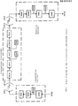
- FIG. 1 shows as non limiting example, a possible block diagram which makes up the system subject of this invention, in which the digital signal to be transmitted (TXSG) is coded through an external code device (EXCD); digital signal TXSG' so obtained (with a bit rate greater than TXSG) is used to modulate through modulator MOD 1, a transmission carrier later amplified by transmitter TEQ 1 and radiated by antenna ANT1.
- the R.F. carrier sent by the transmitter is received by the intermediate transponder through antenna ANT2, receiver REQ2 and demodulator DEMI which reconstitute signal TXSG', save for transmission errors.
- the signal so received is once again coded by internal coder INCD, obtaining a new digital signal TXSG" which has a bit rate even higher than TXSG'.
- Such TXSG" signal is then used to modulate a second RF carrier by means of MOD2 modulator, later amplified by TEQ2 and radiated by antenna ANT3.
- the RF carrier sent by the transponder is received by the receiver terminal through ANT4 and through receiver (REQ2) and demodulation (DEM2) units, a RXSG'' signal is rebuilt, coinciding, save for transmission errors, with signal TXSG".
- Such signal is decoded by internal decoder INDC, obtaining a signal RXSG' which, save for transmission errors, coincides with signal TXSG'.
- This last signal is decoded by external decoder EXDC so as to rebuild signal RXSG, which save for transmission errors, coincides with transmitted signal TXSG.
- the system offered makes possible transmitter terminal - transponder and transponder - receiver terminal links, protected by diversified coding systems chosen as a function of specific requirements.
- the invention regards a concatenated code-decode system for the protection against interference of digital transmissions, through a regenerative transponder.
- the invention may be used in digital telecommunications systems using an intermediate regenerative transponder where it is required to protect terminal-transponder and transponder - terminal links through diversified redundancy codes.
- the system is particularly suited for satellite applications, as the fact of protecting the downlink with an independent code (which is therefore independent of the on board thermal noise quota and up link errors) improves performance at the same band and power levels, when compared to the internal code case made at the transmitter terminal.
- an internal code-decode with on board satellite coding improves down link characteristics at same bandwidth and transmitted power, leaving unchanged up link characteristics (in term of bit rate, power and band). This is particularly advantageous when the satellite is called to receive a plurality of carriers modulated by different digital signals and to transmit through on the downlink, a single carrier modulated by a single digital signal obtained by multiplexing the digital signals received through the up link (FDMA/TDM access).
- FDMA/TDM access FDMA/TDM access
- the available band amplitude in uplink is equal to that available in downlink
- TDM signal bit rate equal to the sum of up link transmitted digital signals bit rates
- down link band will exceed that occupied by RF signal (because all band margins typical of FDMA access are used).
- clock signal CK1 is extracted with trailing edges in line with TXSG' transitions.
- the device required for CK1 extraction isn't shown because already known.
- a signal CK2 is generated at frequency (m+n)/m times CK1 frequency.
- the device required for CK2 generation isn't shown, because already known technology.
- CK2 is generated so that its leading edges coincide with those of CK1 at times T0, Tl ... contained at the bit centre of TXSG' m multiples.
- pulses PRLD and CLR are generated, each lined up with the latest trailing edges of CK1 and CK2 before times T0, Tl ...
- the duration of such pulses must be such that pulse CLR does not start to descend before the end of pulse PRLD.
Landscapes
- Physics & Mathematics (AREA)
- Probability & Statistics with Applications (AREA)
- Engineering & Computer Science (AREA)
- Theoretical Computer Science (AREA)
- Detection And Prevention Of Errors In Transmission (AREA)
- Radio Relay Systems (AREA)
Abstract
Description
- The invention relates to a code-decode system for protection from interference of digital signal transmissions based upon two overlayed code-decoded known respectively as external and internal codecodes. The first (external) is performed by devices housed in the terminal equipment; here coding is made in the transmitter terminal and decoding is made in the receiver terminal. The second code (internal) is made in the intermediate transponder while the corresponding decoding is made in the receiving terminal.
- Figure 1 shows as non limiting example, a possible block diagram which makes up the system subject of this invention, in which the digital signal to be transmitted (TXSG) is coded through an external code device (EXCD); digital signal TXSG' so obtained (with a bit rate greater than TXSG) is used to modulate through
modulator MOD 1, a transmission carrier later amplified bytransmitter TEQ 1 and radiated by antenna ANT1. The R.F. carrier sent by the transmitter is received by the intermediate transponder through antenna ANT2, receiver REQ2 and demodulator DEMI which reconstitute signal TXSG', save for transmission errors. The signal so received is once again coded by internal coder INCD, obtaining a new digital signal TXSG" which has a bit rate even higher than TXSG'. Such TXSG" signal is then used to modulate a second RF carrier by means of MOD2 modulator, later amplified by TEQ2 and radiated by antenna ANT3. - The RF carrier sent by the transponder is received by the receiver terminal through ANT4 and through receiver (REQ2) and demodulation (DEM2) units, a RXSG'' signal is rebuilt, coinciding, save for transmission errors, with signal TXSG". Such signal is decoded by internal decoder INDC, obtaining a signal RXSG' which, save for transmission errors, coincides with signal TXSG'.
- This last signal is decoded by external decoder EXDC so as to rebuild signal RXSG, which save for transmission errors, coincides with transmitted signal TXSG.
- The system offered makes possible transmitter terminal - transponder and transponder - receiver terminal links, protected by diversified coding systems chosen as a function of specific requirements.
- The invention regards a concatenated code-decode system for the protection against interference of digital transmissions, through a regenerative transponder.
- The invention may be used in digital telecommunications systems using an intermediate regenerative transponder where it is required to protect terminal-transponder and transponder - terminal links through diversified redundancy codes. The system is particularly suited for satellite applications, as the fact of protecting the downlink with an independent code (which is therefore independent of the on board thermal noise quota and up link errors) improves performance at the same band and power levels, when compared to the internal code case made at the transmitter terminal.
- Problems which we propose the solve through the adoption of the invention presented:
- This invention may be adopted in a number of applications regarding digital signals transmission and, in particular, it can be used within digital telecommunications, via satellite, where the down link is, generally, more critical than the up-link due to the limited transmitted power available in the satellite.
- The use of an internal code-decode with on board satellite coding improves down link characteristics at same bandwidth and transmitted power, leaving unchanged up link characteristics (in term of bit rate, power and band). This is particularly advantageous when the satellite is called to receive a plurality of carriers modulated by different digital signals and to transmit through on the downlink, a single carrier modulated by a single digital signal obtained by multiplexing the digital signals received through the up link (FDMA/TDM access). Here the adoption of two distinct codes, the external code on signals transmitted through the uplink and the internal code on the down link, optimizes the utilization of band and power in both the up and down links.
- In particular, considering that in the greater part of satellite applications, the available band amplitude in uplink is equal to that available in downlink, in FDMA-TDM systems with TDM signal bit rate equal to the sum of up link transmitted digital signals bit rates, down link band will exceed that occupied by RF signal (because all band margins typical of FDMA access are used).
- By introducing the technique presented in this invention, on the contrary, it is possible to increase TDM signal bit rate by adapting it to the amplitude of the band available, as the bit rate increment is used for internal coding thus improving overall performance of the system.
- Previuos Solutions:
- Literature shows a number of applications of concatenated code-decode using coders and decoders which are internal and external, developed in connection with transmitter and receiver terminals but, to our knowledge, applications in which the internal code is performed within the transponder to protect the sole transponder-receiver terminal link are unknown. By adop-
- The invention is now described with reference to one of its presently preferred forms of implementation, which is reported as a non limiting illustration, with reference to the drawings:
- Figure 1 shows a block diagram of the concatenated code-decode system:

- Figure 2 shows a block diagram of the internal coder (solution no. 1):

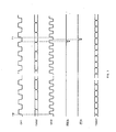
- Figure 3 illustrates the signal waveforms, in which

- Figur 4 is a block diagram of the internal coder (solution no. 2):

- Figure 1 shows the block diagram of a system which uses a concatenated code and transmits a digital signal from a transmitter terminal to a receiver terminal through an intermediate transponder.
- With reference to such figure 1, system operation may be described as follows:
- a. Within the transmitter terminal there is a digital signal (TXSG) which we wish to send to the receiver terminal; signal TXSG is coded through a device EXCD which adds sufficient information to it so as to protect it against possible errors which could be introduced in the transmitter-transponder terminal.
- b. Digital signal TXSG' so obtained (with a bit rate greater than TXSG) is used to modulate, through modulator MOD1, a transmitter carrier, later amplified by transmitter device TEQ1 and radiated through antenna ANTI.
- c. The radio carrier transmitted by the transmitter is received by the transponder through antenna ANT2, receiver REQ2 and demodulator DEM1 which reconstitutes, save for transmission errors, signal TXSG'.
The signal thus received is once again coded the means of the internal coder INCD, obtaining a new digital signal TXSG" which has a bit rate even higher than TXSG'. The type of coding to be adopted and the TXSG " to TXSG' bit rate ratioes are selected and optimized as a function of the transponder-to-receiving-terminal link characteristics (quite independently of the selections operated for TXSG coding into TXSG'). - d. TXSG" is used to modulate, through MOD2 modulator, a second RF carrier, later amplified by TEQ2 and radiated through antenna ANT3.
- e. The radio frequency carrier sent by the transponder is received by the receiving terminal through ANT4 and through receiver REQ2 and demodulation DEM2 signal RXSG " is reconstituted so as to coincide with TXSG " , save for transmission errors.
- f. RXSG " is decoded by internal coder INDC, obtaining RXSG', which, save for residual transmission errors, coincides with signal TXSG'. The latter is decoded by decoder EXDC to reconstitute RXSG, which coincides, save for possible residual transmission errors, with transmitted signal TXSG.
Figure 2 shows a possible implementation of internal coder INCD (figure 1) i-n a configuration which is described as a pure non limiting example, together with the waveforms schematically reported in figure 3. - From Signal TXSG' to be coded, clock signal CK1 is extracted with trailing edges in line with TXSG' transitions. The device required for CK1 extraction isn't shown because already known.
- Starting from signal CK1, the means of a phase locked oscillator, a signal CK2 is generated at frequency (m+n)/m times CK1 frequency. The device required for CK2 generation isn't shown, because already known technology.
- CK2 is generated so that its leading edges coincide with those of CK1 at times T0, Tl ... contained at the bit centre of TXSG' m multiples.
- Starting from signals CK1 and CK2, two pulses PRLD and CLR are generated, each lined up with the latest trailing edges of CK1 and CK2 before times T0, Tl ... The duration of such pulses must be such that pulse CLR does not start to descend before the end of pulse PRLD.
- In presence of the timing signals described, the operation of the circuit in figure 2 may be summarized as follows:
- a. The circuit consists of:
- - n+1 D type bistable memories (Fl, F2,... Fn+1) with data input D, clock input CK, reset input CL and output Q,
- - a shift register SHR1 with m stages with D type serial input, clock input CK1 and parallel output,
- - a shift register SHR2 with m+n stages with parallel input, clock input CK2, load command LD and serial output Q,
- - a plurality of exclusive OR logic gates XOR1, XOR2 ... XORq;
- b. signal CLR resets to 0 the n memories F2, F3 ... Fn+1 immediately before the start of interval Ti ... Ti+1;
- c. the m leading edges of CK1 which follow insert, bit after bit, serial signal TXSG' into shift register SHR1 and into the feedback shift register F2, F3 ... Fn+1 and logic gates XOR1, XOR2 ... XORq;
- d. at the end of an m bit cycle SR1 will be filled with the last m bits of signal TXSG'; the m memories F2, F3 ... Fn+1 will be filled with the n parity bits to be transmitted together with TXSG' m bits to give way to a BCH (Bose-Chaudu- ri-Hocquenghem) (m+n, m) code symbol;
- e. signal PRLD transfers the m+n bits obtained above to SHR2 and they are then sequentially transmitted through memory Fl starting from the next leading edge of CK2 (which coincides with time instant Ti+1);
- f. the cycle repeats with continuity, transmitting in time Ti+1 - Ti+2 the coded symbol during interval Ti - Ti+1. Figure 4 shows, as a pure non limiting example, a second possible implementation of the internal coder (INCD, figure 1).
- Circuit operation is that of figure 2, with the only difference in that the n parity bits to be transmitted together with the m bits of signal TXSG' (from time to time'stored in SHR1) are generated through a look up table rather than through a feedback shift register as that shown in figure 2.
Claims (9)
Applications Claiming Priority (2)
| Application Number | Priority Date | Filing Date | Title |
|---|---|---|---|
| IT48024/86A IT1191903B (en) | 1986-05-15 | 1986-05-15 | CONCATENATED CODING-DECODING SYSTEM FOR PROTECTION AGAINST DISTURBANCES OF DIGITAL TRANSMISSIONS CARRIED OUT THROUGH AN INTERMEDIATE REGENERATIVE REPEATER |
| IT4802486 | 1986-05-15 |
Publications (3)
| Publication Number | Publication Date |
|---|---|
| EP0245781A2 true EP0245781A2 (en) | 1987-11-19 |
| EP0245781A3 EP0245781A3 (en) | 1991-03-20 |
| EP0245781B1 EP0245781B1 (en) | 1993-08-11 |
Family
ID=11264013
Family Applications (1)
| Application Number | Title | Priority Date | Filing Date |
|---|---|---|---|
| EP87106643A Expired - Lifetime EP0245781B1 (en) | 1986-05-15 | 1987-05-07 | Concatenated code-decode system for the protection against interference of digital transmissions through an intermediate regenerative repeater |
Country Status (4)
| Country | Link |
|---|---|
| US (1) | US4800570A (en) |
| EP (1) | EP0245781B1 (en) |
| DE (1) | DE3786948T2 (en) |
| IT (1) | IT1191903B (en) |
Families Citing this family (13)
| Publication number | Priority date | Publication date | Assignee | Title |
|---|---|---|---|---|
| US5087099A (en) * | 1988-09-02 | 1992-02-11 | Stolar, Inc. | Long range multiple point wireless control and monitoring system |
| US5942990A (en) * | 1997-10-24 | 1999-08-24 | Halliburton Energy Services, Inc. | Electromagnetic signal repeater and method for use of same |
| US6177882B1 (en) | 1997-12-01 | 2001-01-23 | Halliburton Energy Services, Inc. | Electromagnetic-to-acoustic and acoustic-to-electromagnetic repeaters and methods for use of same |
| US6144316A (en) * | 1997-12-01 | 2000-11-07 | Halliburton Energy Services, Inc. | Electromagnetic and acoustic repeater and method for use of same |
| US6218959B1 (en) | 1997-12-03 | 2001-04-17 | Halliburton Energy Services, Inc. | Fail safe downhole signal repeater |
| US6018501A (en) * | 1997-12-10 | 2000-01-25 | Halliburton Energy Services, Inc. | Subsea repeater and method for use of the same |
| US6018301A (en) * | 1997-12-29 | 2000-01-25 | Halliburton Energy Services, Inc. | Disposable electromagnetic signal repeater |
| US6320850B1 (en) | 1998-04-24 | 2001-11-20 | Trw Inc. | Satellite communication adaptive control coding |
| US6138261A (en) * | 1998-04-29 | 2000-10-24 | Trw Inc. | Concatenated coding system for satellite communications |
| US6279132B1 (en) | 1998-09-28 | 2001-08-21 | Trw Inc. | Concatenated error control method and system for a processing satellite uplink |
| US6625776B1 (en) | 1998-09-30 | 2003-09-23 | Northrop Grumman Corporation | Adaptive coding scheme for a processing communications satellite |
| DE10000834A1 (en) * | 2000-01-12 | 2001-08-16 | Fraunhofer Ges Forschung | Production of electrically conducting compounds comprises distributing a particulate filler in a polymer matrix, and forming material bridges between the filler particles and the electrically conducting surfaces to be joined |
| GB2424800B (en) * | 2005-04-01 | 2008-02-13 | Toshiba Res Europ Ltd | Wireless communications device |
Family Cites Families (5)
| Publication number | Priority date | Publication date | Assignee | Title |
|---|---|---|---|---|
| US3944723A (en) * | 1974-12-05 | 1976-03-16 | General Electric Company | Station for power line access data system |
| US4261054A (en) * | 1977-12-15 | 1981-04-07 | Harris Corporation | Real-time adaptive power control in satellite communications systems |
| SE417760B (en) * | 1979-05-15 | 1981-04-06 | Ellemtel Utvecklings Ab | SET ON DATA TRANSMISSION BETWEEN A SENDING COMPUTER AND A RECEIVING COMPUTER MONITORING ERRORS AND DEVICE FOR IMPLEMENTATION OF THE SET |
| US4312070A (en) * | 1979-12-07 | 1982-01-19 | Motorola, Inc. | Digital encoder-decoder |
| US4354054A (en) * | 1981-04-16 | 1982-10-12 | Bell Telephone Laboratories, Incorporated | Caboose signal controlled reporting arrangement for a regenerator chain |
-
1986
- 1986-05-15 IT IT48024/86A patent/IT1191903B/en active
-
1987
- 1987-04-30 US US07/044,888 patent/US4800570A/en not_active Expired - Fee Related
- 1987-05-07 EP EP87106643A patent/EP0245781B1/en not_active Expired - Lifetime
- 1987-05-07 DE DE87106643T patent/DE3786948T2/en not_active Expired - Fee Related
Also Published As
| Publication number | Publication date |
|---|---|
| IT1191903B (en) | 1988-03-31 |
| EP0245781B1 (en) | 1993-08-11 |
| DE3786948D1 (en) | 1993-09-16 |
| DE3786948T2 (en) | 1994-04-14 |
| IT8648024A0 (en) | 1986-05-15 |
| EP0245781A3 (en) | 1991-03-20 |
| US4800570A (en) | 1989-01-24 |
Similar Documents
| Publication | Publication Date | Title |
|---|---|---|
| EP0245781A2 (en) | Concatenated code-decode system for the protection against interference of digital transmissions through an intermediate regenerative repeater | |
| RU2191471C2 (en) | Satellite communication system using encoding with parallel integration | |
| EP0369703A2 (en) | Spread spectrum communication system | |
| EP0417072A4 (en) | An encoder/decoder system and methodology utilizing conservative coding with block delimiters, for serial communication | |
| EP0000039A1 (en) | A data transmission process and system to permit substantial reduction of interference between a received first and second digital signal | |
| RU2195072C2 (en) | Mobile station and method for extending information capacity of data frame | |
| EP0926856A2 (en) | Crosstalk suppression in a radio network | |
| EP0989688B1 (en) | Spread spectrum diversity transmitter/receiver | |
| US4523323A (en) | Digital signal communication system for multi-level modulation including unique encoder and decoder | |
| KR100570595B1 (en) | Apparatus for Generating Pseudo Random Numbers, and Related Methods | |
| US3423729A (en) | Anti-fading error correction system | |
| Hamkins et al. | Selection of modulation and codes for deep-space optical communications | |
| RU2097923C1 (en) | Method for transmission of digital information through radio channel with random alternation of operation frequency and device which implements said method | |
| EP1037400B1 (en) | Mitigation of false co-channel uplink reception in a processing satellite communication system using stagger | |
| Ohtsuki et al. | Overlapping multi-pulse pulse position modulation in optical direct detection channel | |
| EP0094254B1 (en) | Integrated scrambler-encoder using pn sequence generator | |
| US5559623A (en) | Method and arrangement for arranging an interception-proof optical link | |
| US4998251A (en) | Method of detecting erasures affecting a digital radio link and a receiver system implementing such a method | |
| Jabri et al. | Adaptive-rate transmission with coding and interleaving for a further improvement in the throughput of meteor-burst communication systems | |
| JPH02266727A (en) | Digital radio communication equipment and error correction circuit used for the same | |
| US6230298B1 (en) | Digital messaging method and apparatus | |
| wut | Coding for satellite and space channels | |
| Siegrneth | Pioneer Mission Support | |
| JPH0754923B2 (en) | Digital modulator | |
| SU1159166A1 (en) | Regenerator for coding and decoding digital information |
Legal Events
| Date | Code | Title | Description |
|---|---|---|---|
| PUAI | Public reference made under article 153(3) epc to a published international application that has entered the european phase |
Free format text: ORIGINAL CODE: 0009012 |
|
| AK | Designated contracting states |
Kind code of ref document: A2 Designated state(s): DE FR GB NL SE |
|
| PUAL | Search report despatched |
Free format text: ORIGINAL CODE: 0009013 |
|
| AK | Designated contracting states |
Kind code of ref document: A3 Designated state(s): DE FR GB NL SE |
|
| 17P | Request for examination filed |
Effective date: 19910918 |
|
| 17Q | First examination report despatched |
Effective date: 19920224 |
|
| GRAA | (expected) grant |
Free format text: ORIGINAL CODE: 0009210 |
|
| AK | Designated contracting states |
Kind code of ref document: B1 Designated state(s): DE FR GB NL SE |
|
| RIN1 | Information on inventor provided before grant (corrected) |
Inventor name: LOSQUADRO, GIACINTO Inventor name: PERROTTA, GIORGIO |
|
| REF | Corresponds to: |
Ref document number: 3786948 Country of ref document: DE Date of ref document: 19930916 |
|
| ET | Fr: translation filed | ||
| PGFP | Annual fee paid to national office [announced via postgrant information from national office to epo] |
Ref country code: SE Payment date: 19940418 Year of fee payment: 8 |
|
| PGFP | Annual fee paid to national office [announced via postgrant information from national office to epo] |
Ref country code: GB Payment date: 19940427 Year of fee payment: 8 |
|
| PGFP | Annual fee paid to national office [announced via postgrant information from national office to epo] |
Ref country code: FR Payment date: 19940530 Year of fee payment: 8 |
|
| PGFP | Annual fee paid to national office [announced via postgrant information from national office to epo] |
Ref country code: NL Payment date: 19940531 Year of fee payment: 8 |
|
| PLBE | No opposition filed within time limit |
Free format text: ORIGINAL CODE: 0009261 |
|
| STAA | Information on the status of an ep patent application or granted ep patent |
Free format text: STATUS: NO OPPOSITION FILED WITHIN TIME LIMIT |
|
| 26N | No opposition filed | ||
| EAL | Se: european patent in force in sweden |
Ref document number: 87106643.7 |
|
| PG25 | Lapsed in a contracting state [announced via postgrant information from national office to epo] |
Ref country code: DE Effective date: 19950201 |
|
| PG25 | Lapsed in a contracting state [announced via postgrant information from national office to epo] |
Ref country code: GB Effective date: 19950507 |
|
| PG25 | Lapsed in a contracting state [announced via postgrant information from national office to epo] |
Ref country code: SE Effective date: 19950508 |
|
| PG25 | Lapsed in a contracting state [announced via postgrant information from national office to epo] |
Ref country code: NL Effective date: 19951201 |
|
| GBPC | Gb: european patent ceased through non-payment of renewal fee |
Effective date: 19950507 |
|
| NLV4 | Nl: lapsed or anulled due to non-payment of the annual fee |
Effective date: 19951201 |
|
| EUG | Se: european patent has lapsed |
Ref document number: 87106643.7 |
|
| PG25 | Lapsed in a contracting state [announced via postgrant information from national office to epo] |
Ref country code: FR Effective date: 19960229 |
|
| REG | Reference to a national code |
Ref country code: FR Ref legal event code: ST |
|
| REG | Reference to a national code |
Ref country code: FR Ref legal event code: ST |