EP0245547A1 - Système électronique pour la neurostimulation des viscères pelviens - Google Patents
Système électronique pour la neurostimulation des viscères pelviens Download PDFInfo
- Publication number
- EP0245547A1 EP0245547A1 EP86303600A EP86303600A EP0245547A1 EP 0245547 A1 EP0245547 A1 EP 0245547A1 EP 86303600 A EP86303600 A EP 86303600A EP 86303600 A EP86303600 A EP 86303600A EP 0245547 A1 EP0245547 A1 EP 0245547A1
- Authority
- EP
- European Patent Office
- Prior art keywords
- nerve
- bladder
- sacral
- control system
- electrode
- Prior art date
- Legal status (The legal status is an assumption and is not a legal conclusion. Google has not performed a legal analysis and makes no representation as to the accuracy of the status listed.)
- Granted
Links
Images


Classifications
-
- A—HUMAN NECESSITIES
- A61—MEDICAL OR VETERINARY SCIENCE; HYGIENE
- A61N—ELECTROTHERAPY; MAGNETOTHERAPY; RADIATION THERAPY; ULTRASOUND THERAPY
- A61N1/00—Electrotherapy; Circuits therefor
- A61N1/18—Applying electric currents by contact electrodes
- A61N1/32—Applying electric currents by contact electrodes alternating or intermittent currents
- A61N1/36—Applying electric currents by contact electrodes alternating or intermittent currents for stimulation
- A61N1/36007—Applying electric currents by contact electrodes alternating or intermittent currents for stimulation of urogenital or gastrointestinal organs, e.g. for incontinence control
Definitions
- This invention relates generally to an electronic control system for controlling bodily functions and, more particularly, to the utilization of one or more electrodes on selected nerve bundles and control means for applying pulse trains to the electrode(s) to control, regulate or treat such functions.
- the physiology of the bladder and bowel is closely linked to the urethral muscle physiology of the pelvic floor (levator ani muscle) and its related urethral and anal sphincters.
- the bladder For the bladder to store urine and for the bowel to serve as a reservoir for feces, two opposite, but complementary, behaviors are found. In particular, the bladder and rectum must relax and the urethral and anal sphincters must remain contracted. The reverse is true during evacuation of either urine or feces, i.e., the urethral or anal sphincter will relax along with the pelvic floor, and subsequently the bladder and rectum will contract.
- An electronic control system for controlling bladder or bowel evacuation ( Figures 1-11), for modulating the symptoms resulting from a loss of coordination between normally synchronized functions of visceral organs (Chart I), and for treating incontinence by increasing sphincter tonus (Chart II).
- controlling not only include the selective control, modulation or treatment of a particular organ on a continuous basis, but further include isolated or periodic stimulation of the organ for diagnostic or rehabilitation purposes, e.g., neuromodulation of muscular behavior to rehabilitate muscular dysfunction in the pelvic floor without stimulating the pelvic nerve controlling the bladder's detrusor muscle.
- organ as used herein broadly means an independent part of the human body that performs a special function or functions, including visceral organs, such as the bladder, bowel and colon, and associated sphincters, cuffs and muscles.
- the electronic control system includes electrode means adapted to be positioned on selected nerve bundles for electrically stimulating the nerve bundles.
- a control means is adapted to sequentially apply pulse trains to the electrode means sequentially to control the function of one organ or a number of organs simultaneously.
- Figures 1 and 18 schematically illustrates the pelvic plexus region of a human, including the nervous system for controlling bladder and bowel evacuation and related functions.
- the nervous system includes a somatic nerve system of fibers (or nerve bundles) S and an autonomic nerve system of nerve bundles A, finding their immediate origin at sacral segments S2, S3 and S4 of the spinal cord and sacrum, i.e., the triangular bone positioned below the lumbar vertebrae and comprising five fused sacral vertebrae that are wedged dorsally between the two hip bones.
- the main nerve supply to the detrusor muscle of a bladder B emanates primarily from sacral segment S3, a lesser amount from sacral segment S2, and a still lesser amount from sacral segment S4, i.e., "response” refers to bladder response.
- the electronic control system described in this application is adapted for controlling the bladder or bowel and related functions, modulating symptoms resulting from a loss of coordination between the normally synchronized functions of the bladder and bowel and their associated sphincters and treating incontinence by increasing sphincter tonus. Either permanent surgical implantation or temporary percutaneous implantation for nerve stimulation purposes is applicable. Also, electrodes can be implanted either unilaterally or bilaterally.
- the main nerve supply emanating from each sacral segment S2, S3 and S4 comprises two components or roots, namely, a dorsal root D and a ventral root V.
- the dorsal root is primarily sensory to transmit sensation to the spinal cord whereas the ventral root is primarily motor to transmit motor impulses from the spinal cord to bladder B and associated sphincter.
- the dorsal and ventral roots for each nerve are, in fact, normally joined together and their fibres or bundles mixed to progress as a single trunk.
- Bundles of the nerve trunk are divided into somatic nerve bundles S that connect to voluntary muscles and autonomic nerve bundles A that connect to visceral organs, such as bladder B.
- Dorsal root D can be separated from ventral root V since only stimulation of the motor nerve bundles of a particular ventral root are contemplated in many procedures. In this manner, the motor nerve bundles can be stimulated without inducing pain and without generating impulses along the sensory passageway.
- Somatic nerves S and autonomic nerves A can also be separated from each other.
- the somatic nerve can be solely stimulated.
- the autonomic nerve bundles could be stimulated. Stimulation of the entire nerve trunk would function to stimulate each of the dorsal, ventral, somatic and autonomic nerve bundles.
- responses obtained with pre-operative evaluation of responses to stimulation recorded urodynamically could indicate that the S2 sacral nerve constitutes the main motor supply to external sphincter E, whereas the S3 sacral nerve constitutes the main motor supply to bladder B.
- the S3 sacral nerve would be utilized to control the detrusor muscle and thus the contracting function of bladder B alone, whereas the S2 sacral nerve would be utilized to control the muscles controlling the continence function of external sphincter E.
- Figure 1 and 3-11 illustrate various combinations of operative procedures for effecting the desired neurostimulation for specific case studies (male or female) wherein simultaneous control for coordinating the synchronized functions of a bladder or bowel and its associated sphincter is effected.
- a quadriplegic who has suffered a neck injury and damage to his spinal cord will normally require an operative procedure wherein control of bladder B and external sphincter E are of the utmost importance.
- the quadriplegic may suffer uncontrolled bowel evacuation, for example, which can be concurrently controlled when bladder control is effected by such operative procedure.
- Fig.ures 1 and 3-11 are primarily discussed in connection with the simultaneous control of the coordinated and synchronized functions of a bladder and its sphincter, they ae also applicable to the control of a bowel and its sphincter.
- Figure 1 illustrates an operative procedure whereby continence and evacuation of bladder B is closely controlled in a particular patient, such as a quadriplegic.
- the particular operative procedure utilized will depend upon a patient's ability to respond to electrical stimuli at strategic locations on his or her nervous system in the pelvic plexus region. For example, it is assumed in the Figure 1 operative procedure that the patient is unable to self-control his or her bladder functions and that such locations have been evaluated pre-operatively.
- the dorsal (sensory) root D and ventral (motor) root V are surgically separated bilaterally on each side of sacral segment S3.
- An electrode 2 is then attached by sutures or otherwise implanted on each ventral root V for purposes of external excitation and stimulation, as hereinafter described with reference to the micturition control system illustrated in Figure 12.
- each superior somatic nerve S s is sectioned at 3 bilaterally to eliminate any increase in the resistance normally provided by the levator ani muscles at least partially surrounding external sphincter E and controlled by superior somatic nerve S s .
- Superior somatic innervation (S s ) is commonly described in anatomy books (e.g., CIBA or Gray's) as part of the innervation to the levator ani muscles, whereas inferior somatic innervation (S I ) is classically described as the pudendal nerve in Alcock's Canal. It should be noted that an internal sphincter I will normally open automatically when the bladder contracts and thus requires no artificial control.
- Pre-operative electrostimulation was achieved by the use of a bipolar probe for stimulating the various nerve bundles.
- a nerve stimulator was then used to deliver a DC square wave for stimulation purposes.
- the nerve stimulator may be of the type manufactured by Grass Medical Instruments of Quincy, Massachusetts, U.S.A., under Model No. S-44.
- the electrodes are of the standard type.
- each electrode may constitute a bipolar cuff electrode having an inside diameter approximating 3-5 mm. and provided with 1 mm. by 2 mm. platinum contacts having a 3 mm. separation placed outside each other about the periphery of ventral nerve root V. This type of electrode is manufactured by Avery Laboratories, Inc. under Model No. 390.
- suitable receivers in the form of implantable silastic-coated units containing an antenna coil, adapted to receive RF (radio frequency) pulses from an external transmitter, are implanted subcutaneously in the patient to transmit pulses to the electrodes to control bladder evacuation in a controlled manner.
- RF radio frequency
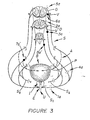
- FIG 3 illustrates optional variations to the Figure 1 operative procedure which will potentially enhance bladder evacuation.
- each of the S2, S3 and S4 sacral nerves are separated to isolate the respective ventral and dorsal roots thereof.
- Pudendal or inferior somatic nerve S I is then sectioned unilaterally to isolate external sphincter E on one side.
- Dorsal root D of the S3 sacral nerve is then sectioned at 2a to thus isolate the sensory function thereof.
- Electrode 3a is then implanted on the entire S3 sacral nerve unilaterally, with or without dorsal rhizotomies at other sacral levels.
- the S3 sacral nerve is then sectioned at 4a unilaterally (or bilaterally), downstream of pelvic nerve P to isolate this nerve's contribution to inferior somatic nerve S I . It should be noted that electrode 3a is thus positioned on the S3 sacral nerve to stimulate the detrusor muscles of bladder B, via pelvic nerve P.
- the dorsal root is sectioned at 5a unilaterally (or bilaterally) and an electrode 6a is suitably implanted on the ventral root V of the S2 sacral nerve.
- an electrode 6a is suitably implanted on the ventral root V of the S2 sacral nerve.
- superior somatic nerve S s is preferably sectioned bilaterally, as described above in reference to the Figure 1 operative procedure, to eliminate any additional increase in resistance from contraction of the levator ani muscle when the bladder is contracting for evacuation purposes.
- the above options will also tend to eliminate or minimize a response in the pelvic floor sphincter which would otherwise prevent low resistance voiding of the bladder synchronous with stimulation.
- Thes optional variations address the possibility that excessive residual sphincter activity remains with stimulation after the Figure 1 operative procedure has been attempted.
- Sphincter response may be reflexly produced which suggests the need for dorsal sectioning at 2a and 5a in Figure 3, or directly produced to suggest sectioning 1a of inferior somatic S I , unilaterally or bilaterally.
- the above steps must, of course, be carefully evaluated prior to the selected operative procedure so as not to compromise continence or the contraction of the bladder or bowel or nerves controlling the erection process.
- Additional optional procedures may include percutaneous implantation of an electrode 7a ⁇ on sacral nerve S3 and/or S4, upstream of the point whereat the autonomic nerve roots forming pelvic nerve P separate from the respective sacral nerve proper, to aid in bladder contraction through the pelvic nerve.
- a further option contemplates implantation of a cuff electrode 8a ⁇ around sacral nerve S4, either unilaterally, as shown, or bilaterally, to assist in the control of bladder evacuation. It should be understood that above sectioning steps 2a and 5a, as well as the implantation of electrodes 3a, 6a and 8a ⁇ , require laminectomy, i.e., incision of the posterior arch of the vertebrae.
- Figure 4 illustrates an operative procedure wherein an electrode 1b is implanted onto the S3 sacral nerve through a sacral foramen without excising the posterior arch of the vertebrae.
- a second electrode 2b may be implanted in a like manner on the S4 sacral nerve, either in addition to or in lieu of electrode 1b.
- These electrode implants may be effected unilaterally, as illustrated, or bilaterally, depending on the pre-operative test results.
- superior somatic nerve S s is sectioned at 3 ⁇ , either unilaterally or bilaterally as illustrated in Figure 4.
- the system thus effected by the Figure 4 operative procedure will normally provide means for selectively eliminating or suppressing spastic detrusor activity, spastic urethral and pelvic floor activity and spastic anal sphincter. Such system may further suppress or enhance erection.
- Figure 5 illustrates the percutaneous implantation of electrode 1b through the dorsum and the sacral forament of sacral segment S3 for the purpose of selectively stimulating the S3 sacral nerve.
- electrode 1b can be inserted through the hollow spinal needle used for such stimulation with the wire lead connected to the electrode being suitably sutured in place, as shown, for attachment to a receiver (not shown), as will be described more fully hereinafter.
- This percutaneous method can also be used to temporarily implant an electrode on any one or more of the sacral nerves for testing purposes, i.e., to record activity in the bladder in response to stimulation of one or more of the nerves by the electrodes to thus determine which nerve or nerves are controlling the bladder functions.
- This procedure can be conducted unilaterally or bilaterally.
- electrode 1b could be percutaneously placed on the S3 sacral nerve with the external extremity of the wire attached to the electrode then being taped to the skin, along with a receiver connected thereto. The patient could then resume his day-to-day lifestyle and be allowed to stimulate the nerve or nerves artificially via a transmitter compatible with the receiver. If the response is positive and complete relief is achieved, the electrode or electrodes could be permanently implanted or temporarily implanted for the purpose of correcting any dysfunction by "retraining" the nerve and associated muscles. Should little or no improvement result, the same procedure could be followed to accurately ascertain which nerve or nerves require stimulation.
- this invention contemplates not only the implantation of one or more electrodes in the sacral nervous system for controlling evacuation of a visceral organ or the like, but also contemplates use of such electrodes and procedures to rehabilitate muscle dysfunction by neuromodulation of muscular behavior, as described more fully hereinafter with reference to Chart II.
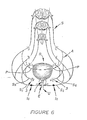
- Figure 6 illustrates an optional variation for controlling evacuation of bladder B.
- superior somatic nerve Ss is sectioned at 3, either unilaterally or bilaterally, as shown.
- electrodes 1c are implanted on inferior somatic nerve S I , unilaterally or bilaterally depending on the response obtained from pre- operative evaluation of responses to stimulation recorded urodynamically.
- electrodes 1d are implanted bilaterally on inferior somatic nerve S I and electrodes 2d are implanted bilaterally on the S3 sacral nerve percutaneously.
- electrodes 1e are implanted bilaterally on superior somatic nerve S s and electrodes 2e are implanted bilaterally on inferior somatic nerve S I .
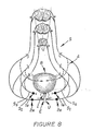
- Figure 9 illustrates another operative procedure for controlling continence and bladder contraction.
- electrodes 1 f are implanted bilaterally on inferior somatic nerve S I .
- Superior somatic S s is sectioned bilaterally, as illustrated, and a pair of second electrodes 2 f are implanted bilaterally on the separated ventral root V of the S3 sacral nerve.
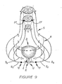
- FIG 10 illustrates an operative procedure particularly adapted for achieving continence due to muscle weakness of the bladder or bowel.
- Electrodes 1g and 2g are implanted bilaterally on inferior somatic nerve S I and on the S3 sacral nerve, as illustrated.
- an electrode 2g ⁇ could be implanted on the ventral root thereof.
- an electrode 3g is implanted unilaterally on the S3 sacral nerve percutaneously.
- an electrode 3g ⁇ could be implanted on the S4 sacral nerve, also percutaneously.
- FIG 10 another electrode 2g could be implanted on superior somatic nerve S s , either unilaterally or bilaterally, as illustrated.
- the Figure 10 operative procedure illustrates the two components of sphincter contraction with the number of implants and their locations being dependent on recruitability of muscle activity in individual patients and/or the ability of percutaneous technique to adequately couple the electrodes with the appropriate nerve bundles.
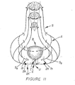
- Figure 11 illustrates an operative procedure particularly adapted for controlling autonomic dysreflexia and bladder storage.
- Superior somatic nerve S s is sectioned bilaterally at 1h and electrodes 2h are implanted on the inferior somatic nerve bilaterally.
- electrode 2h could be implanted unilaterally with the opposite side of the inferior somatic nerve being sectioned at 2h ⁇ .
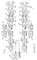
- Figure 12 illustrates a micturition control system adapted to transmit electrical current (radio frequency) pulses to electrodes implanted on selected nerves of the above-described systems, such as the implantations illustrated in Figure 9, i.e., leads 26 and 27 connected to electrodes 1f and leads 47 and 48 connected to electrodes 2f.
- the control system comprises an external control-transmitter system 10, and a receiver system 11 implanted on a patient for transmitting electrical current pulses to the electrodes.
- the two-fold purpose of this system is to efficiently (1) maintain urethral tone and hence continence of urine until bladder voiding is desired; and (2) provide bladder contraction and voiding on demand by a patient or his attendant, for patients having bladder or pelvic problems or paralysis.
- Figure 12 illustrates the electronic signal, transmitter and receiver components of the system whereas Figure 14 illustrates the types of signals and their timed relationship in the electronic control component of the system.
- the symbol SR as used herein depicts a component of the control system connected to an electrode implanted on a particular sacral nerve or root, whereas IS depicts connection to inferior somatic nerve S I , controlling continence.
- the ongoing control of continence is provided by stimulation of a selected nerve or nerves as described above.
- This control function is accomplished by the ongoing stimulation produced by a stimulus pulse oscillator 12 (OSC) and associated circuits.
- the oscillator preferably operating at a rate within the range of from 5 to 40 pulses per second, emits a square wave output signal that drives and IS stimulus pulse width one-shot (O.S.) 13 which produces signal pulses with widths within the range of from 50 to 500 microseconds, as illustrated in Figure 14.
- These pulses are controlled by AND gates 14 and 15 to produce separate trains of pulses, also shown in Figure 14.
- Gating is produced by an IS pulse train duration oscillator 16. It should be noted in Figure 12 that the two phases of the square wave output of oscillator 16 can be obtained by the illustrated inverter circuit.
- the frequency of the square wave output of oscillator 16 is preferably selected from within the range of from 0.1 to 0.5 Hertz (cycles per second).
- This oscillator is controlled by an IS stimulus control flip-flop 17. When the flip-flop is set, it allows oscillator 16 to run to enable gates 14 and 15 to transmit signal pulses (Figure 14) to turn on and off radio frequency (RF) generators or oscillators 18 and 19.
- the antennas are inductively coupled to receivers 24 and 25 which detect the separate sets of RF pulses and transmit such detected pulses to a particular nerve-implanted electrodes via electrical leads 26 and 27, respectively.
- Receivers 24 and 25, as well as hereinafter described receivers 45 and 46, are each subcutaneously implanted on a particular patient.
- switch 28 When it is desired to evacuate bladder B, and assuming that the four energized electrodes are properly implanted for a particular patient in the manner described above, the patient or his attendant will momentarily close a switch 28.
- Transmitter 10 and attendant antennas 22 and 23 are, of course, suitably housed as an external unit, readily accessible to the patient.
- the closing of switch 28 will activate an SR stimulus timer 29 for a selected length of time, preferably within the range of from 10 to 40 seconds.
- the output Q of timer 29 goes high to activate an SR delay oscillator 30 and resets IS stimulus control flip-flop 17 so that it turns off the IS pulse train duration oscillator 16.
- stimulation of the urethral sphincter closure for example, is disabled.
- the Q output of timer 29 goes low to allow flip-flop 31 to be set on a signal from SR delay 30.
- the output signal from SR delay 30 sets a flip-flop which then starts an SR stimulus pulse oscillator 32 and SR pulse train duration oscillator 33.
- Oscillator 32 will generate a square wave signal that is preferably selected from the range of from 15 to 50 Hertz, as diagrammatically illustrated in Figure 14.
- the output from oscillator 15 then drives an SR stimulus pulse width O.S. 34 which produces signal pulses at a selected width of from 50 to 500 microseconds.
- These pulses are ANDED by gates 35 and 36 with the output of oscillator 33 to produce trains of pulses, as illustrated in Figure 14. It should be noted in Figure 12 that the opposite phases of the square wave output of oscillator 33 may also be obtained by the use of the illustrated inverter circuit.
- Gate control originates at oscillator 33 which has a selected frequency within the range of from 0.1 to 0.5 Hertz.
- the pulse trains from AND gates 35 and 36 control RF oscillators 37 and 38, respectively. These are turned on when the pulses are high.
- the RF signals are amplified in RF amplifiers 39 and 40 wherein the output amplitudes are controlled by variable resistors 39 ⁇ and 40 ⁇ , respectively.
- the outputs of the amplifiers drive antennas 43 and 44 which inductively couple the signal through the patient's skin and to implanted receivers 45 and 46.
- the receivers detect the RF pulses and transmit the stimulus pulses to the particular implanted electrodes, via electrical leads 47 and 48.
- the output reverses, as illustrated in Figure 14.
- the Q output goes low and enables flip-flop 17 to activate oscillator 16 when the "set" signal is transmitted from IS delay O.S. 49.
- the Q output of timer 29 goes high and activates 49.
- the output sets IS stimulus circuitry until bladder evacuation is again required.
- the Q output from timer 29 also resets flip-flop 31 and thus disables oscillators 32 and 33 to end the bladder voiding stimulation.
- the above oscillators may be made of the astable multivibrator type, manufactured by Intersil Corp., U.S.A., under Model No. 1CM7556.
- the one-shot (O.S.) monstable multivibrators may also be of the common type manufactured by Intersil Corp.
- the flip-flops (F.F.) may constitute the type manufactured by RCA Corporation, U.S.A., under Model No. CD4027B, whereas the gates may be of the type manufactured by the same company under Model No. DC4081B.
- Receivers 24, 25, 45 and 46 may constitute a standard implantable silastic-coated unit containing an antenna coil adapted to receive the "rf" pulses transmitted from their respective transmitter antennas 22, 23, 43 and 44.
- each receiver may be similar to the type manufactured by Avery Laboratories, Inc., U.S.A., under Model No. I-110 (bipolar).
- Figure 13 illustrates a typical circuit 55 for the receiver.
- a coil 56 functions as an antenna that receives the inductive signal transmitted thereto by a respective transmitter antenna which is placed externally of the patient, adjacent to the location of the implanted receivers.
- a capacitor 57 in conjunction with coil 56, provides a tuned circuit that is tuned to one of the four different frequencies of the transmitter.
- the other three receivers are tuned to their respective transmitting frequencies when the system uses four separate radio frequencies.
- the frequencies may be the same for all four transmitters with the four receivers being tuned to the same transmitting frequency.
- the four transmitting antennas and the four implanted receivers must be separated so that the signal in any one transmitting antenna will not provide false signals in the other three receivers.
- a diode 58 detects, by half-wave rectification, the pulsed stimulus current from the RF bursts.
- Resistors 59 and 60 and capacitors 61 and 62 function to filter the RF out of the stimulus signal which is lead to the nerve electrodes via electrical leads, described above. Maximum stimulation of the nerves is achieved when the negative pole is attached to the distal electrode contact on the nerve and the corresponding positive pole is the proximal contact of the nerve electrode assembly.
- Figure 12 control system can be suitably modified to control the energization of the electrodes used in the above-described procedures and variations thereof.
- the portion of the system for controlling pulse imputs to antennas 24 and 25 could be utilized to energize electrodes 2 in Figure 1.
- Figures 15 and 16 illustrate typical electrode implantations for stimulation purposes.
- Figure 17 diagramatically illustrates the timing of stimulus pulse trains to electrode pairs with each electrode contact being activated essentially 100/n % of the time for n active (cathodol) contacts.
- One way to prevent or prolong the onset of fatigue is to stimulate the system in a non-continuous and time-modulated format. Otherwise stated, alternate stimulation of different groups of nerve bundles in a nerve system with short bursts of stimulus pulses provides such desiderata. This method of stimulation allows the muscles and nerves to recover between trains of stimuli while other nerves and muscles are being activated to continue the desired physiological effect.
- Time-modulation of stimuli to nerves to achieve muscle contraction can be accomplished in at least two ways.
- Figure 15 illustrates a first approach wherein a multiplicity of electrode pairs 63, 64 and 65, 66 are attached to separate nerve bundles. Each pair of electrodes are activated so that each electrode is "on" for only a portion of a particular stimulation cycle, e.g., with four electrode pairs, each would be stimulating its nerve bundle approximately one-quarter of the time (in general, 100/n % of the time for n electrode pairs). It should be noted in Figure 7, although shown in coincidence, that an overlap or dead time can be affected between the stimuli trains.
- Figure 16 illustrates a second approach to accomplish time modulation of nerve stimulation wherein a multiplicity of active electrode contacts are employed on a single electrode.
- the intensity of the stimulus pulses must be sufficiently low so that all nerve bundles are not stimulated by a single active electrode contact. Nonetheless, the amplitude of the stimulus pulses must be sufficiently high so that the desired physiological function can be achieved.
- each electrode contact would function to activate the proper proportional number of fibres, e.g., in the case of two contacts each contact would activate one-half of the nerve bundles and in the case of four contacts each contact would active one-quarter of the nerve bundles, etc.
- the desired physiological function must be achieved when a single contact is used on that particular nerve bundle.
- An exception would be in applications wherein other nerve bundles are similarly connected to a similar time-modulated system. In the latter application, partial nerve stimulation from the combined group of stimulated nerve bundles would accomplish the desired physiological results.
- the physiology of the bladder and bowel is closely linked to the urethral muscle physiology of the pelvic floor and its related urethral and anal sphincters.
- the sequences for storage (continence) and evacuation suggest that the somatic muscles of the pelvic floor are principally responsible for both continence and evacuation.
- the visceral organs i.e., bowel/bladder, are either released from the reflex inhibition or are directly facilitated into contracting, or both.
- neural control of the pelvic muscles largely determines the state of activity of the pelvic viscera (bowel, bladder, and possible erection).
- a simple example is the "hold" reflex used to suppress a strong urge to void or defecate at inconvenient times.
- the visceral dysfunction can be demonstrated especially in the case of the bladder--to be associated with pelvic muscle dysfunction, with the behavior of the bladder being a direct result of excessive inhibition (e.g., inability to void completely because of an inability to relax the urinary sphincter completely), or excessive triggering of bladder contractions (i.e., a precipitate urge to void one's bladder) because of a breakdown in the efficiency of reflex coordination between the bladder and pelvic muscles.
- a similar analogy can be made for problems affecting the bowel (as well as erection). Correction of the pelvic muscle dysfunction can thus serve to correct the visceral muscle dysfunction.
- Other effects described by patients have included the reduction of severe neck spasm, back spasm and leg cramps.
- Visceral muscle dysfunctions which can be considered a result of overfacilitated activity include the spastic colon, interstitial cystitis, detrusor instability, cardiovascular problems, such as migraine headache or palpatations, and bladder retention syndromes.
- Somatic muscle dysfunctions directly resulting from poor neural regulation and overfacilitated behavior include: pelvic pain syndromes, frequency syndromes (pelvic floor and/or urethral instability), incontinency due to poor relaxation or instability of the sphincters (either bowel or bladder), and incontinence following prostatectomy.
- the following bowel problems may also be treatable by a sacral or pudendal nerve electrode implant, namely, "spastic colon", and fecal incontinence either from spasticity or incompetence of the anal sphincter, and infrequent or too frequent bowel movements.
- a spinoff benefit that has been noted is the treatment of foot drop. It appears that the planter flexion of the distal half of the foot and toes gives added stability to the gait. It has long been believed that foot drop was the result of a weakness in the muscles controlled by the perineal nerve. Stimulation of this nerve has been used to lift the foot using the foot dorsiflexors, but with limited success. Foot drop has been shown to improve by stimulation of sacral S3 nerve root N3 because of a better push the foot has as a result of planter flexion.
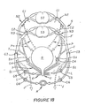
- Figure 18 illustrates letters depicting various components of the pelvic plexus region of a human that are common to those shown in Figures 1-11.
- the following listing includes newly discussed components, shown in Figure 18, as well as the common ones:
- Methods herein disclosed can be used to either modulate symptoms resulting from a loss of coordination between the normally synchronized functions of organs, including bladder B, rectum R and associated bladder sphincters E and I and the anal sphincter for rectum R (Chart I), or to treat incontinence by increasing sphincter tonus (Chart II).
- Sacral nerves N2 and N3 originate at sacral segments S2 and S3, respectively, and form pelvic nerve P that controls contraction of a detrusor muscle surrounding bladder B.
- the sacral nerves also form somatic components that subdivide into: (1) superior somatic nerve S S ; and (2) pudendal nerve T that includes (a) inferior somatic nerve S I connected to muscles controlling external sphincter E of bladder B, (b) anal branch L connected to the anal sphincter for rectum R, and (c) dorsal nerve J connected to the penis.
- the nerve bundles connected to the various sphincters are controllable at a lower level of electrical stimulation that that required to control the muscles for the bladder and rectum proper.
- Figure 18 illustrates six cuff electrodes C1-C6 adapted to be positioned on selected nerve bundles (while simultaneously isolating adjacent nerve bundles) either individually or in combination with at least one other electrode for stimulation purposes. Such positioning step occurs after identifying the anatomical location and functional characteristics of the selected nerve bundle or bundles. Pulse trains are then applied sequentially to the electrode or electrodes to control the function of the organ.
- electrodes C1-C6 modulate or control the function(s) of the following organs:
- the following chart indicates twenty-one different combinations of electrode placement (unilaterally or bilaterally) for modulating the above-discussed symptoms resulting from a loss or coordination between a persons's organs, including bladder B, rectum R and associated sphincters:
- the following second chart indicates electrode placement (unilaterally or bilaterally) for treatment of incontinence by increasing sphincter tonus either by direct stimulation of a sphincter muscle or by modulating reflex control mechanisms so that more effective sphincter tonus results:
- reflex control mechanisms means those nerve bundles that control interrelated activity between bladder B and pelvic floor musculature (primarily levator ani muscle I) as they can reflexively influence each other by either inhibition or facilitation.
- electrode combinations (1) and (8) in Chart I each affect bladder B, bladder sphincter E and anal sphincter R, in combination (8) the bladder will be relatively more responsive since the main pelvic nerve supply P emanates primarily from sacral segment S3 and to a lesser amount from sacral segment S2.
- the site or sites chosen for implantation of an electrode is determined by careful evaluation of a patient's problems. Such evaluations consist of symptom analysis, physical deficits or variations in muscle behavior of the lower extremities and pelvic muscles, or loss of sensation, the results of urodynamic testing and the results of test stimulation of the various sacral nerves.
- a temporary electrode is normally inserted percutaneously into one or more of the sacral foramena and specific nerve roots test stimulated for a response. When a desired response is obtained, a temporary electrode can be "floated" (e.g., Foramene electrode F in Figure 18) in the vicinity of the nerve or nerves. This procedure allows the patient to have a three to five day trial of stimulation to evaluate the therapeutic benefits of stimulation.
- the patient can be further evaluated for the response to be obtained by percutaneously implanting an electrode on one or more of the selected nerve bundles or an electrode can be permanently implanted, either via sacral laminectomy and placement of an electrode directly on a specific sacral nerve or by placing an electrode on the sacral foramene without performing a laminectomy.
- Therapeutic benefits are thus obtained by stimulation of specific pelvic muscles.
Priority Applications (4)
| Application Number | Priority Date | Filing Date | Title |
|---|---|---|---|
| US06/611,836 US4607639A (en) | 1984-05-18 | 1984-05-18 | Method and system for controlling bladder evacuation |
| EP86303600A EP0245547B1 (fr) | 1986-05-12 | 1986-05-12 | Système électronique pour la neurostimulation des viscères pelviens |
| DE8686303600T DE3673644D1 (de) | 1986-05-12 | 1986-05-12 | Elektronisches system zur nervenstimulation von beckenorganen. |
| AT86303600T ATE55697T1 (de) | 1986-05-12 | 1986-05-12 | Elektronisches system zur nervenstimulation von beckenorganen. |
Applications Claiming Priority (1)
| Application Number | Priority Date | Filing Date | Title |
|---|---|---|---|
| EP86303600A EP0245547B1 (fr) | 1986-05-12 | 1986-05-12 | Système électronique pour la neurostimulation des viscères pelviens |
Publications (2)
| Publication Number | Publication Date |
|---|---|
| EP0245547A1 true EP0245547A1 (fr) | 1987-11-19 |
| EP0245547B1 EP0245547B1 (fr) | 1990-08-22 |
Family
ID=8196006
Family Applications (1)
| Application Number | Title | Priority Date | Filing Date |
|---|---|---|---|
| EP86303600A Expired - Lifetime EP0245547B1 (fr) | 1984-05-18 | 1986-05-12 | Système électronique pour la neurostimulation des viscères pelviens |
Country Status (3)
| Country | Link |
|---|---|
| EP (1) | EP0245547B1 (fr) |
| AT (1) | ATE55697T1 (fr) |
| DE (1) | DE3673644D1 (fr) |
Cited By (14)
| Publication number | Priority date | Publication date | Assignee | Title |
|---|---|---|---|---|
| EP0473131A2 (fr) * | 1990-08-29 | 1992-03-04 | Wetzel, Horst | Stimulateur électrique pour le traitement de l'incontinence chez la femme |
| WO1993024176A1 (fr) * | 1992-05-23 | 1993-12-09 | Keith Edward Tippey | Stimulation electrique pour le traitement de l'incontinence et d'autres troubles neuromusculaires |
| EA000044B1 (ru) * | 1996-02-01 | 1998-02-26 | Анатолий Геннадьевич Кудряшов | Стимулятор |
| WO2000015293A1 (fr) * | 1998-09-16 | 2000-03-23 | Axon Engineering, Inc. | Stimulation combinee des racines sacree ventrale et dorsale destinee a reguler la fonction vesicale |
| US6928320B2 (en) | 2001-05-17 | 2005-08-09 | Medtronic, Inc. | Apparatus for blocking activation of tissue or conduction of action potentials while other tissue is being therapeutically activated |
| US7142925B1 (en) * | 1998-09-16 | 2006-11-28 | Axon Engineering, Inc. | Combined stimulation of ventral and dorsal sacral roots for control of bladder function |
| WO2007106303A2 (fr) * | 2006-03-03 | 2007-09-20 | Ams Research Corporation | Bandelette à électrodes pour le traitement de l'incontinence urinaire d'effort et par impériosité |
| US7328069B2 (en) | 2002-09-06 | 2008-02-05 | Medtronic, Inc. | Method, system and device for treating disorders of the pelvic floor by electrical stimulation of and the delivery of drugs to the left and right pudendal nerves |
| US7328068B2 (en) | 2003-03-31 | 2008-02-05 | Medtronic, Inc. | Method, system and device for treating disorders of the pelvic floor by means of electrical stimulation of the pudendal and associated nerves, and the optional delivery of drugs in association therewith |
| US7369894B2 (en) | 2002-09-06 | 2008-05-06 | Medtronic, Inc. | Method, system and device for treating disorders of the pelvic floor by electrical stimulation of the sacral and/or pudendal nerves |
| US7427280B2 (en) | 2002-09-06 | 2008-09-23 | Medtronic, Inc. | Method, system and device for treating disorders of the pelvic floor by delivering drugs to various nerves or tissues |
| US9427573B2 (en) | 2007-07-10 | 2016-08-30 | Astora Women's Health, Llc | Deployable electrode lead anchor |
| US9731112B2 (en) | 2011-09-08 | 2017-08-15 | Paul J. Gindele | Implantable electrode assembly |
| CN110392592A (zh) * | 2016-12-23 | 2019-10-29 | 西奈山伊坎医学院 | 评价全身麻醉的患者的喉返神经与迷走神经完整性的方法和系统 |
Families Citing this family (10)
| Publication number | Priority date | Publication date | Assignee | Title |
|---|---|---|---|---|
| US6735474B1 (en) | 1998-07-06 | 2004-05-11 | Advanced Bionics Corporation | Implantable stimulator system and method for treatment of incontinence and pain |
| US6941171B2 (en) | 1998-07-06 | 2005-09-06 | Advanced Bionics Corporation | Implantable stimulator methods for treatment of incontinence and pain |
| US6871099B1 (en) | 2000-08-18 | 2005-03-22 | Advanced Bionics Corporation | Fully implantable microstimulator for spinal cord stimulation as a therapy for chronic pain |
| US7054689B1 (en) | 2000-08-18 | 2006-05-30 | Advanced Bionics Corporation | Fully implantable neurostimulator for autonomic nerve fiber stimulation as a therapy for urinary and bowel dysfunction |
| US8467875B2 (en) | 2004-02-12 | 2013-06-18 | Medtronic, Inc. | Stimulation of dorsal genital nerves to treat urologic dysfunctions |
| US8160710B2 (en) | 2006-07-10 | 2012-04-17 | Ams Research Corporation | Systems and methods for implanting tissue stimulation electrodes in the pelvic region |
| US20100049289A1 (en) | 2007-07-10 | 2010-02-25 | Ams Research Corporation | Tissue anchor |
| US9539433B1 (en) | 2009-03-18 | 2017-01-10 | Astora Women's Health, Llc | Electrode implantation in a pelvic floor muscular structure |
| US8380312B2 (en) | 2009-12-31 | 2013-02-19 | Ams Research Corporation | Multi-zone stimulation implant system and method |
| US9220887B2 (en) | 2011-06-09 | 2015-12-29 | Astora Women's Health LLC | Electrode lead including a deployable tissue anchor |
Citations (2)
| Publication number | Priority date | Publication date | Assignee | Title |
|---|---|---|---|---|
| US3870051A (en) * | 1972-04-27 | 1975-03-11 | Nat Res Dev | Urinary control |
| US3888261A (en) * | 1973-12-07 | 1975-06-10 | Medtronic Inc | Time shared stimulator |
-
1986
- 1986-05-12 AT AT86303600T patent/ATE55697T1/de not_active IP Right Cessation
- 1986-05-12 DE DE8686303600T patent/DE3673644D1/de not_active Expired - Fee Related
- 1986-05-12 EP EP86303600A patent/EP0245547B1/fr not_active Expired - Lifetime
Patent Citations (2)
| Publication number | Priority date | Publication date | Assignee | Title |
|---|---|---|---|---|
| US3870051A (en) * | 1972-04-27 | 1975-03-11 | Nat Res Dev | Urinary control |
| US3888261A (en) * | 1973-12-07 | 1975-06-10 | Medtronic Inc | Time shared stimulator |
Non-Patent Citations (2)
| Title |
|---|
| IEEE ENGINEERING IN MEDICINE AND BIOLOGY, vol. 2, no. 2, June 1983, pages 31-36, IEEE, New York, US; R.A. SCHMIDT et al.: "Neural prostheses and bladder control" * |
| WIRELESS WORLD, vol. 90, no. 1576, January 1984, pages 61-64, Sheepen Place, Olchester, GB; T. IVALL: "Radio activated implant for bladder control" * |
Cited By (20)
| Publication number | Priority date | Publication date | Assignee | Title |
|---|---|---|---|---|
| EP0473131A3 (en) * | 1990-08-29 | 1992-12-02 | Wetzel, Horst | Electrical stimulator for the treatment of female incontinence |
| EP0473131A2 (fr) * | 1990-08-29 | 1992-03-04 | Wetzel, Horst | Stimulateur électrique pour le traitement de l'incontinence chez la femme |
| WO1993024176A1 (fr) * | 1992-05-23 | 1993-12-09 | Keith Edward Tippey | Stimulation electrique pour le traitement de l'incontinence et d'autres troubles neuromusculaires |
| EA000044B1 (ru) * | 1996-02-01 | 1998-02-26 | Анатолий Геннадьевич Кудряшов | Стимулятор |
| WO2000015293A1 (fr) * | 1998-09-16 | 2000-03-23 | Axon Engineering, Inc. | Stimulation combinee des racines sacree ventrale et dorsale destinee a reguler la fonction vesicale |
| AU758611B2 (en) * | 1998-09-16 | 2003-03-27 | Axon Engineering, Inc. | Combined stimulation of ventral and dorsal sacral roots for control of bladder function |
| US7142925B1 (en) * | 1998-09-16 | 2006-11-28 | Axon Engineering, Inc. | Combined stimulation of ventral and dorsal sacral roots for control of bladder function |
| US6928320B2 (en) | 2001-05-17 | 2005-08-09 | Medtronic, Inc. | Apparatus for blocking activation of tissue or conduction of action potentials while other tissue is being therapeutically activated |
| US7433734B2 (en) | 2001-05-17 | 2008-10-07 | Medtronic, Inc. | Apparatus and method for blocking activation of tissue or conduction of action potentials while other tissue is being therapeutically activated |
| US7369894B2 (en) | 2002-09-06 | 2008-05-06 | Medtronic, Inc. | Method, system and device for treating disorders of the pelvic floor by electrical stimulation of the sacral and/or pudendal nerves |
| US7328069B2 (en) | 2002-09-06 | 2008-02-05 | Medtronic, Inc. | Method, system and device for treating disorders of the pelvic floor by electrical stimulation of and the delivery of drugs to the left and right pudendal nerves |
| US7427280B2 (en) | 2002-09-06 | 2008-09-23 | Medtronic, Inc. | Method, system and device for treating disorders of the pelvic floor by delivering drugs to various nerves or tissues |
| US7328068B2 (en) | 2003-03-31 | 2008-02-05 | Medtronic, Inc. | Method, system and device for treating disorders of the pelvic floor by means of electrical stimulation of the pudendal and associated nerves, and the optional delivery of drugs in association therewith |
| WO2007106303A3 (fr) * | 2006-03-03 | 2008-04-10 | Ams Res Corp | Bandelette à électrodes pour le traitement de l'incontinence urinaire d'effort et par impériosité |
| WO2007106303A2 (fr) * | 2006-03-03 | 2007-09-20 | Ams Research Corporation | Bandelette à électrodes pour le traitement de l'incontinence urinaire d'effort et par impériosité |
| EP3150250A1 (fr) * | 2006-03-03 | 2017-04-05 | AMS Research Corporation | Bandelette à électrodes destinée à traiter le stress et l'incontinence par impériosité |
| US9889298B2 (en) | 2006-03-03 | 2018-02-13 | Astora Women's Health, Llc | Electrode sling for treating stress and urge incontinence |
| US9427573B2 (en) | 2007-07-10 | 2016-08-30 | Astora Women's Health, Llc | Deployable electrode lead anchor |
| US9731112B2 (en) | 2011-09-08 | 2017-08-15 | Paul J. Gindele | Implantable electrode assembly |
| CN110392592A (zh) * | 2016-12-23 | 2019-10-29 | 西奈山伊坎医学院 | 评价全身麻醉的患者的喉返神经与迷走神经完整性的方法和系统 |
Also Published As
| Publication number | Publication date |
|---|---|
| ATE55697T1 (de) | 1990-09-15 |
| EP0245547B1 (fr) | 1990-08-22 |
| DE3673644D1 (de) | 1990-09-27 |
Similar Documents
| Publication | Publication Date | Title |
|---|---|---|
| US4771779A (en) | System for controlling bladder evacuation | |
| US4607639A (en) | Method and system for controlling bladder evacuation | |
| US4703755A (en) | Control system for the stimulation of two bodily functions | |
| EP0245547B1 (fr) | Système électronique pour la neurostimulation des viscères pelviens | |
| US4739764A (en) | Method for stimulating pelvic floor muscles for regulating pelvic viscera | |
| US7643880B2 (en) | Methods and systems for selectively inhibiting neural transmission of somatic fibers | |
| US9950160B2 (en) | System and method for electrical stimulation of anorectal structures to treat anal dysfunction | |
| US7894913B2 (en) | Systems and methods of neuromodulation stimulation for the restoration of sexual function | |
| US6735474B1 (en) | Implantable stimulator system and method for treatment of incontinence and pain | |
| US8396555B2 (en) | Apparatus for stimulating components in, on, or near the pudendal nerve or its branches to achieve selective physiologic responses | |
| US20080071321A1 (en) | Systems and methods of neuromodulation stimulation for the restoration of sexual function | |
| US20050113878A1 (en) | Method, system and device for treating various disorders of the pelvic floor by electrical stimulation of the pudendal nerves and the sacral nerves at different sites | |
| US20100010563A1 (en) | Method and Apparatus for Treating Fecal Incontinence | |
| US20100016657A1 (en) | Method and Apparatus for Managing Erectile Dysfunction | |
| US20050209651A1 (en) | System and method for treatment of sexual dysfunction | |
| Thüroff et al. | Functional Pattern of Sacral Root Stimulation in Dogs II. Urethral Closure | |
| CA1297164C (fr) | Methode et systeme de controle electronique des visceres abdominales par stimulation neuro-electrique | |
| JPS62286471A (ja) | 解剖学的系における器官の協調及び同期機能制御装置 | |
| Kerrebroeck | Neuromodulation and other electrostimulatory techniques | |
| Schmidt et al. | Neuromicturition: Extradural sacral nerve-root stimulation: guidelines for patient selection and implant technique | |
| Rakovec | Reflex electrical stimulation for urinary incontinence | |
| Naumann | Electrical restoration of the micturition reflex | |
| EV et al. | Intradural sacral rhizotomies and implantation of an anterior sacral root stimulator in the treatment of neurogenic bladder dysfunction after spinal cord injury. Surgical technique and complications | |
| AU2006301939A1 (en) | A method and apparatus for treating fecal incontinence |
Legal Events
| Date | Code | Title | Description |
|---|---|---|---|
| PUAI | Public reference made under article 153(3) epc to a published international application that has entered the european phase |
Free format text: ORIGINAL CODE: 0009012 |
|
| AK | Designated contracting states |
Kind code of ref document: A1 Designated state(s): AT BE CH DE FR GB IT LI LU NL SE |
|
| 17P | Request for examination filed |
Effective date: 19880112 |
|
| 17Q | First examination report despatched |
Effective date: 19890223 |
|
| GRAA | (expected) grant |
Free format text: ORIGINAL CODE: 0009210 |
|
| ITF | It: translation for a ep patent filed |
Owner name: INTERBREVETTI S.R.L. |
|
| AK | Designated contracting states |
Kind code of ref document: B1 Designated state(s): AT BE CH DE FR GB IT LI LU NL SE |
|
| REF | Corresponds to: |
Ref document number: 55697 Country of ref document: AT Date of ref document: 19900915 Kind code of ref document: T |
|
| REF | Corresponds to: |
Ref document number: 3673644 Country of ref document: DE Date of ref document: 19900927 |
|
| ET | Fr: translation filed | ||
| PLBE | No opposition filed within time limit |
Free format text: ORIGINAL CODE: 0009261 |
|
| STAA | Information on the status of an ep patent application or granted ep patent |
Free format text: STATUS: NO OPPOSITION FILED WITHIN TIME LIMIT |
|
| 26N | No opposition filed | ||
| ITTA | It: last paid annual fee | ||
| EPTA | Lu: last paid annual fee | ||
| EAL | Se: european patent in force in sweden |
Ref document number: 86303600.0 |
|
| REG | Reference to a national code |
Ref country code: GB Ref legal event code: IF02 |
|
| PGFP | Annual fee paid to national office [announced via postgrant information from national office to epo] |
Ref country code: FR Payment date: 20040519 Year of fee payment: 19 |
|
| PGFP | Annual fee paid to national office [announced via postgrant information from national office to epo] |
Ref country code: SE Payment date: 20040521 Year of fee payment: 19 |
|
| PGFP | Annual fee paid to national office [announced via postgrant information from national office to epo] |
Ref country code: CH Payment date: 20040524 Year of fee payment: 19 |
|
| PGFP | Annual fee paid to national office [announced via postgrant information from national office to epo] |
Ref country code: LU Payment date: 20040528 Year of fee payment: 19 |
|
| PGFP | Annual fee paid to national office [announced via postgrant information from national office to epo] |
Ref country code: BE Payment date: 20040622 Year of fee payment: 19 |
|
| PGFP | Annual fee paid to national office [announced via postgrant information from national office to epo] |
Ref country code: DE Payment date: 20040630 Year of fee payment: 19 |
|
| PGFP | Annual fee paid to national office [announced via postgrant information from national office to epo] |
Ref country code: NL Payment date: 20050416 Year of fee payment: 20 |
|
| PGFP | Annual fee paid to national office [announced via postgrant information from national office to epo] |
Ref country code: AT Payment date: 20050420 Year of fee payment: 20 |
|
| PGFP | Annual fee paid to national office [announced via postgrant information from national office to epo] |
Ref country code: GB Payment date: 20050504 Year of fee payment: 20 |
|
| PG25 | Lapsed in a contracting state [announced via postgrant information from national office to epo] |
Ref country code: LU Free format text: LAPSE BECAUSE OF NON-PAYMENT OF DUE FEES Effective date: 20050512 Ref country code: IT Free format text: LAPSE BECAUSE OF NON-PAYMENT OF DUE FEES;WARNING: LAPSES OF ITALIAN PATENTS WITH EFFECTIVE DATE BEFORE 2007 MAY HAVE OCCURRED AT ANY TIME BEFORE 2007. THE CORRECT EFFECTIVE DATE MAY BE DIFFERENT FROM THE ONE RECORDED. Effective date: 20050512 |
|
| PG25 | Lapsed in a contracting state [announced via postgrant information from national office to epo] |
Ref country code: SE Free format text: LAPSE BECAUSE OF NON-PAYMENT OF DUE FEES Effective date: 20050513 |
|
| PG25 | Lapsed in a contracting state [announced via postgrant information from national office to epo] |
Ref country code: LI Free format text: LAPSE BECAUSE OF NON-PAYMENT OF DUE FEES Effective date: 20050531 Ref country code: CH Free format text: LAPSE BECAUSE OF NON-PAYMENT OF DUE FEES Effective date: 20050531 Ref country code: BE Free format text: LAPSE BECAUSE OF NON-PAYMENT OF DUE FEES Effective date: 20050531 |
|
| BERE | Be: lapsed |
Owner name: THE *REGENTS OF THE UNIVERSITY OF CALIFORNIA Effective date: 20050531 |
|
| PG25 | Lapsed in a contracting state [announced via postgrant information from national office to epo] |
Ref country code: DE Free format text: LAPSE BECAUSE OF NON-PAYMENT OF DUE FEES Effective date: 20051201 |
|
| REG | Reference to a national code |
Ref country code: CH Ref legal event code: PL |
|
| EUG | Se: european patent has lapsed | ||
| PG25 | Lapsed in a contracting state [announced via postgrant information from national office to epo] |
Ref country code: FR Free format text: LAPSE BECAUSE OF NON-PAYMENT OF DUE FEES Effective date: 20060131 |
|
| REG | Reference to a national code |
Ref country code: FR Ref legal event code: ST Effective date: 20060131 |
|
| PG25 | Lapsed in a contracting state [announced via postgrant information from national office to epo] |
Ref country code: GB Free format text: LAPSE BECAUSE OF EXPIRATION OF PROTECTION Effective date: 20060511 |
|
| PG25 | Lapsed in a contracting state [announced via postgrant information from national office to epo] |
Ref country code: NL Free format text: LAPSE BECAUSE OF EXPIRATION OF PROTECTION Effective date: 20060512 |
|
| REG | Reference to a national code |
Ref country code: GB Ref legal event code: PE20 |
|
| NLV7 | Nl: ceased due to reaching the maximum lifetime of a patent |
Effective date: 20060512 |
|
| BERE | Be: lapsed |
Owner name: THE *REGENTS OF THE UNIVERSITY OF CALIFORNIA Effective date: 20050531 |