EP0245212A2 - Nockenbetätigte Mikroschaltereinheit - Google Patents
Nockenbetätigte Mikroschaltereinheit Download PDFInfo
- Publication number
- EP0245212A2 EP0245212A2 EP87830093A EP87830093A EP0245212A2 EP 0245212 A2 EP0245212 A2 EP 0245212A2 EP 87830093 A EP87830093 A EP 87830093A EP 87830093 A EP87830093 A EP 87830093A EP 0245212 A2 EP0245212 A2 EP 0245212A2
- Authority
- EP
- European Patent Office
- Prior art keywords
- drive shaft
- microswitch
- cam
- cams
- actuated
- Prior art date
- Legal status (The legal status is an assumption and is not a legal conclusion. Google has not performed a legal analysis and makes no representation as to the accuracy of the status listed.)
- Granted
Links
- 230000000717 retained effect Effects 0.000 claims abstract description 3
- 230000005540 biological transmission Effects 0.000 description 3
- 238000010276 construction Methods 0.000 description 3
- 230000033001 locomotion Effects 0.000 description 3
- 239000004020 conductor Substances 0.000 description 1
- 238000009434 installation Methods 0.000 description 1
- 239000000463 material Substances 0.000 description 1
- 238000000034 method Methods 0.000 description 1
- 230000001105 regulatory effect Effects 0.000 description 1
Images


Classifications
-
- H—ELECTRICITY
- H01—ELECTRIC ELEMENTS
- H01H—ELECTRIC SWITCHES; RELAYS; SELECTORS; EMERGENCY PROTECTIVE DEVICES
- H01H19/00—Switches operated by an operating part which is rotatable about a longitudinal axis thereof and which is acted upon directly by a solid body external to the switch, e.g. by a hand
- H01H19/54—Switches operated by an operating part which is rotatable about a longitudinal axis thereof and which is acted upon directly by a solid body external to the switch, e.g. by a hand the operating part having at least five or an unspecified number of operative positions
- H01H19/60—Angularly-movable actuating part carrying no contacts
- H01H19/62—Contacts actuated by radial cams
- H01H19/623—Adjustable cams
Definitions
- the present invention relates to a cam-actuated microswitch unit in which the switch -actuating position of the cams is adjustable.
- microswitch-actuated control units are currently based on the concept of mounting the or each cam fixedly on a rotatable shaft to actuate a microswitch the position of which is adjustable.
- the rotatable shaft has an associated quadrant with a graduated scale marked thereon, against which the actuation position of the microswitches may be read.
- the object of the present invention is that of providing a new type of microswitch unit capable of being used in a wide range of different applications and, in practice, reversing conventional principles of construction, with the advantage of having an extremely compact and functional assembly.
- a cam-actuated microswitch unit in which the point at which the or each microswitch is actuated is adjustable, characterised in that it comprises at least one microswitch fixedly connected to a supporting frame for actuation by the or a respective cam carried on a drive shaft connectable to a measuring instrument or detector apparatus so that the angular position of the drive shaft is related to a physical quantity detected by the said instrument or apparatus, in that the relative angular orientation of the or each cam on the drive shaft is selectively adjustable to determine the point at which the or an associated said microswitch is actuated, in that the selected relative angular position of the or each cam and the drive shaft is retained by friction, and in that the relative angular orientation of the or each cam with respect to the drive shaft is indicated by an index pointer movable with respect to a movable graduated scale carried fixedly on the drive shaft for rotation therewith.
- One advantage of this invention is that of providing a cam-actuated microswitch unit in which all the operations relating to the selection of the values at which the microswitches are operated can be effected in an extremely rapid and simplified manner.
- Another advantage of the present invention is that of providing a microswitch unit which can exercise multiple switching functions on external electrical circuits connected to the microswitches themselves by cables or conductors, by suitably positioning individual control indices in selected positions on a graduated scale of an indicator.
- the opening or closing of the switches in respective electrical circuits may serve any appropriate purpose, for example it may serve to regulate and/or control the function of any type of machine, or to monitor or complete any process.
- the microswitch unit must be mounted on appropriate detector apparatus or on a measuring instrument.
- Another advantage of the present invention is that it provides a microswitch unit which, by its peculiar constructional characteristics, is able to offer the widest guarantees of reliability and safety in use.
- the present microswitch unit allows the operation of any type of machine or installation to be regulated and/or controlled by operating on any determined parameter, which may be, for example, pressure, temperature, vacuum, time or any other measurable physical quantity, and switching may be selected to occur if the measured quantity exceeds a selected value or if it falls below a selected value.
- any determined parameter which may be, for example, pressure, temperature, vacuum, time or any other measurable physical quantity
- the switch unit of the present invention is easily obtainable starting from elements and materials which are commonly available on the market, and which is therefore very advantageous from an economic point of view.
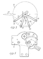
- the cam-actuated microswitch unit of the invention comprises a plurality of microswitches 1 which are fixedly connected to a supporting framework, generally indicated with the reference numeral 2. Unlike the prior art arrangements the positions of the microswitches 1 are not variable to set the switching positions. In the illustrated example there are four microswitches positioned in diametrically opposite pairs.
- the microswitches 1 are isolated from one another by means of insulating plates 3 and are each provided with a cam follower roller 4 which can be engaged by a respective cam 5. All the cams 5 are carried on a rotatable drive shaft 6 which is associated with detector apparatus or a measuring instrument (not illustrated in the drawings) by means of which the value of the physical quantity in relation to which the microswitches are intended to be actuated can be displayed by means of a pointer 13 fixed to the end of the shaft 6.
- the pointer 13 is formed integrally with a disc 12 marked with a graduated scale which will hereinafter be referred to as the moving pointer scale.
- the pointer 13 itself sweeps over a fixed graduated scale (not shown) to indicate the instantaneous values of the physical quantity under determination, which will depend, of course, on the nature of the measuring instrument or detector apparatus to which the microswitch unit of the invention is fitted.
- the moving pointer scale and the fixed graduated scale must be related to one another and cover the same range.
- the cams 5 are mounted on the rotating shaft 6 and frictionally held in place to have the possibility of being turned with respect to the shaft 6 to vary their angular position, and therefore the angular position of the shaft 6 at which the associated microswitch is actuated.
- the cams Upon rotation of the shaft 6 the cams are carried around with it by virtue of the frictional resistance to operate the microswitches at points in the arc of rotation of the shaft 6 determined by the cam setting. This cam setting movement is achieved by overcoming the frictional resistance.
- cams 5 as is best seen in Figure 4 which shows all four cams in different angular positions, are semi-circular in shape and are associated, by means of axially extending pins 7, with positioning arms 20 which have index pointers 10 variously positionable with respect to the graduated pointer scale 11 on the pointer disc 12 which is rigidly connected to the drive shaft 6.
- the arms 20 carrying the index pointers 10 are separated from one another by means of separators indicated 21.
- the positioning of the cams 5 with respect to the drive shaft 6 is effected by means of the pins 7, which engage at one end in the respective cams whilst at the other end they are connected to the levers 20 which are frictionally mounted on the drive shaft 6.
- the number of microswitches 1 and the number of associated cams 5 can be varied as required simply by extending the unit axially or by adding more microswitches at different angular positions, the only limitation on the number of microswitches which can be used is the rotary couple available at the drive shaft: it is evident that this couple, necessary to overcome the friction as the curved surface of each cam moves with respect to the cam follower of the associated microswitch depends exclusively on the type of apparatus or measuring instrument for which the unit is intended.
- microswitch unit of the invention has very reduced dimensions and the setting of the microswitch actuation positions can be effected quickly and easily without creating difficulties either in construction or in use.
- conventional arrangements currently used in the production of microswitch units it is possible to obtain considerable advantages both from a structural point of view and from a functional point of view.
Landscapes
- Rotary Switch, Piano Key Switch, And Lever Switch (AREA)
- Mechanisms For Operating Contacts (AREA)
Applications Claiming Priority (2)
| Application Number | Priority Date | Filing Date | Title |
|---|---|---|---|
| IT2037586 | 1986-05-09 | ||
| IT20375/86A IT1189113B (it) | 1986-05-09 | 1986-05-09 | Gruppo di microinterruttori,azionato da came o leve di intervento,variamente posizionabili |
Publications (3)
| Publication Number | Publication Date |
|---|---|
| EP0245212A2 true EP0245212A2 (de) | 1987-11-11 |
| EP0245212A3 EP0245212A3 (en) | 1989-11-15 |
| EP0245212B1 EP0245212B1 (de) | 1993-03-17 |
Family
ID=11166175
Family Applications (1)
| Application Number | Title | Priority Date | Filing Date |
|---|---|---|---|
| EP87830093A Expired - Lifetime EP0245212B1 (de) | 1986-05-09 | 1987-03-12 | Nockenbetätigte Mikroschaltereinheit |
Country Status (4)
| Country | Link |
|---|---|
| US (1) | US4727227A (de) |
| EP (1) | EP0245212B1 (de) |
| DE (1) | DE3784763T2 (de) |
| IT (1) | IT1189113B (de) |
Cited By (1)
| Publication number | Priority date | Publication date | Assignee | Title |
|---|---|---|---|---|
| GB2313480A (en) * | 1996-05-24 | 1997-11-26 | Daimler Benz Ag | Cam wheel |
Families Citing this family (2)
| Publication number | Priority date | Publication date | Assignee | Title |
|---|---|---|---|---|
| GB2196054B (en) * | 1986-09-25 | 1991-05-08 | Ohi Seisakusho Co Ltd | An openable roof structure for a vehicle |
| DE3744629C1 (de) * | 1987-12-31 | 1989-06-01 | Gulde Regelarmaturen Gmbh & Co | Vorrichtung mit einem Initiator |
Family Cites Families (8)
| Publication number | Priority date | Publication date | Assignee | Title |
|---|---|---|---|---|
| US3032004A (en) * | 1960-04-14 | 1962-05-01 | Gen Electric | Adjustment device between a dial and its shaft |
| US3090397A (en) * | 1960-10-06 | 1963-05-21 | Smith & Sons Ltd S | Level indicating and control instruments |
| DE1640304B1 (de) * | 1966-03-05 | 1970-08-20 | Eduard Hermle | Schaltwerk |
| US3451026A (en) * | 1967-07-03 | 1969-06-17 | Qualitrol Corp | Remote indicating thermometer circuit control device |
| GB1254932A (en) * | 1969-01-31 | 1971-11-24 | Saia Ag | Improvements in or relating to control devices |
| US3678758A (en) * | 1971-07-23 | 1972-07-25 | Frank W Murphy Mfg Inc | Pressure indicating and limiting instrument |
| US3914770A (en) * | 1974-04-08 | 1975-10-21 | United Electric Controls Co | Temperature control recorder |
| DE2943923A1 (de) * | 1979-10-31 | 1981-05-14 | Theiner GmbH, 7000 Stuttgart | elektromechanisches schaltwerk |
-
1986
- 1986-05-09 IT IT20375/86A patent/IT1189113B/it active
- 1986-12-30 US US06/947,842 patent/US4727227A/en not_active Expired - Lifetime
-
1987
- 1987-03-12 EP EP87830093A patent/EP0245212B1/de not_active Expired - Lifetime
- 1987-03-12 DE DE8787830093T patent/DE3784763T2/de not_active Expired - Fee Related
Cited By (1)
| Publication number | Priority date | Publication date | Assignee | Title |
|---|---|---|---|---|
| GB2313480A (en) * | 1996-05-24 | 1997-11-26 | Daimler Benz Ag | Cam wheel |
Also Published As
| Publication number | Publication date |
|---|---|
| EP0245212B1 (de) | 1993-03-17 |
| DE3784763D1 (de) | 1993-04-22 |
| EP0245212A3 (en) | 1989-11-15 |
| US4727227A (en) | 1988-02-23 |
| DE3784763T2 (de) | 1993-09-23 |
| IT8620375A1 (it) | 1987-11-09 |
| IT8620375A0 (it) | 1986-05-09 |
| IT1189113B (it) | 1988-01-28 |
Similar Documents
| Publication | Publication Date | Title |
|---|---|---|
| EP0771681B1 (de) | Rotationsdetektor in Kraftwagen | |
| US3943421A (en) | Food processing control apparatus | |
| US4022078A (en) | Shift control mechanism | |
| SE443748B (sv) | For en korbar maskin med atminstone tva hydraulikkretsar avsedd enhandsomkopplare | |
| US8420959B2 (en) | Manual drive | |
| US4748861A (en) | Electronic display measuring device | |
| EP0245212B1 (de) | Nockenbetätigte Mikroschaltereinheit | |
| JP2001513252A (ja) | タップ位置指示器 | |
| US5542279A (en) | Method of incorporating wide tolerance set point potentiometers into devices with fixed orientation setpoint indicator scales | |
| GB1380031A (en) | Device for setting and indicating the nominal and the actual value respectively of an automatically controlled quantity | |
| JPS6141440B2 (de) | ||
| US3937910A (en) | Timer having a variable operation period | |
| US2729727A (en) | Variable impedance device | |
| US3418857A (en) | Reference mechanism for a shaft-mounted rotatable element | |
| US4135661A (en) | Control device for a valve actuator | |
| US3288950A (en) | Clutch apparatus for counter switch mechanism | |
| US3825704A (en) | Microswitch device actuatable at two preset values of a measurable variable | |
| US3534315A (en) | Material testing | |
| US3533294A (en) | Directly settable controller | |
| US2528967A (en) | Circuit standardizing actuating mechanism | |
| US3090397A (en) | Level indicating and control instruments | |
| US3356944A (en) | Decimal and range indicating means for electrical measuring apparatus | |
| US4274075A (en) | Electronic multi-range variable resistor | |
| US3405359A (en) | Extended-range indicating instruments | |
| US1638838A (en) | Mer mfg |
Legal Events
| Date | Code | Title | Description |
|---|---|---|---|
| PUAI | Public reference made under article 153(3) epc to a published international application that has entered the european phase |
Free format text: ORIGINAL CODE: 0009012 |
|
| AK | Designated contracting states |
Kind code of ref document: A2 Designated state(s): BE CH DE ES FR GB LI NL SE |
|
| PUAL | Search report despatched |
Free format text: ORIGINAL CODE: 0009013 |
|
| AK | Designated contracting states |
Kind code of ref document: A3 Designated state(s): BE CH DE ES FR GB LI NL SE |
|
| 17P | Request for examination filed |
Effective date: 19900228 |
|
| 17Q | First examination report despatched |
Effective date: 19920610 |
|
| GRAA | (expected) grant |
Free format text: ORIGINAL CODE: 0009210 |
|
| AK | Designated contracting states |
Kind code of ref document: B1 Designated state(s): BE CH DE ES FR GB LI NL SE |
|
| PG25 | Lapsed in a contracting state [announced via postgrant information from national office to epo] |
Ref country code: BE Effective date: 19930317 Ref country code: NL Effective date: 19930317 Ref country code: FR Effective date: 19930317 Ref country code: LI Effective date: 19930317 Ref country code: CH Effective date: 19930317 |
|
| REF | Corresponds to: |
Ref document number: 3784763 Country of ref document: DE Date of ref document: 19930422 |
|
| PG25 | Lapsed in a contracting state [announced via postgrant information from national office to epo] |
Ref country code: ES Free format text: LAPSE BECAUSE OF FAILURE TO SUBMIT A TRANSLATION OF THE DESCRIPTION OR TO PAY THE FEE WITHIN THE PRESCRIBED TIME-LIMIT Effective date: 19930628 |
|
| REG | Reference to a national code |
Ref country code: CH Ref legal event code: PL |
|
| EN | Fr: translation not filed | ||
| NLV1 | Nl: lapsed or annulled due to failure to fulfill the requirements of art. 29p and 29m of the patents act | ||
| PLBE | No opposition filed within time limit |
Free format text: ORIGINAL CODE: 0009261 |
|
| STAA | Information on the status of an ep patent application or granted ep patent |
Free format text: STATUS: NO OPPOSITION FILED WITHIN TIME LIMIT |
|
| 26N | No opposition filed | ||
| EAL | Se: european patent in force in sweden |
Ref document number: 87830093.8 |
|
| REG | Reference to a national code |
Ref country code: GB Ref legal event code: IF02 |
|
| PGFP | Annual fee paid to national office [announced via postgrant information from national office to epo] |
Ref country code: DE Payment date: 20040309 Year of fee payment: 18 |
|
| PGFP | Annual fee paid to national office [announced via postgrant information from national office to epo] |
Ref country code: GB Payment date: 20050309 Year of fee payment: 19 |
|
| PG25 | Lapsed in a contracting state [announced via postgrant information from national office to epo] |
Ref country code: DE Free format text: LAPSE BECAUSE OF NON-PAYMENT OF DUE FEES Effective date: 20051001 |
|
| PG25 | Lapsed in a contracting state [announced via postgrant information from national office to epo] |
Ref country code: GB Free format text: LAPSE BECAUSE OF NON-PAYMENT OF DUE FEES Effective date: 20060312 |
|
| GBPC | Gb: european patent ceased through non-payment of renewal fee |
Effective date: 20060312 |
|
| EUG | Se: european patent has lapsed | ||
| PGFP | Annual fee paid to national office [announced via postgrant information from national office to epo] |
Ref country code: SE Payment date: 20060309 Year of fee payment: 20 |