EP0245080A2 - Motorzusammenbau - Google Patents
Motorzusammenbau Download PDFInfo
- Publication number
- EP0245080A2 EP0245080A2 EP87304013A EP87304013A EP0245080A2 EP 0245080 A2 EP0245080 A2 EP 0245080A2 EP 87304013 A EP87304013 A EP 87304013A EP 87304013 A EP87304013 A EP 87304013A EP 0245080 A2 EP0245080 A2 EP 0245080A2
- Authority
- EP
- European Patent Office
- Prior art keywords
- motor
- compressor
- cylinder
- shaft
- axis
- Prior art date
- Legal status (The legal status is an assumption and is not a legal conclusion. Google has not performed a legal analysis and makes no representation as to the accuracy of the status listed.)
- Withdrawn
Links
- 239000000463 material Substances 0.000 claims abstract description 11
- 239000004033 plastic Substances 0.000 claims abstract description 9
- 229920003023 plastic Polymers 0.000 claims abstract description 9
- 239000002184 metal Substances 0.000 claims abstract description 4
- 230000008878 coupling Effects 0.000 claims abstract description 3
- 238000010168 coupling process Methods 0.000 claims abstract description 3
- 238000005859 coupling reaction Methods 0.000 claims abstract description 3
- 238000005553 drilling Methods 0.000 abstract description 6
- XLYOFNOQVPJJNP-UHFFFAOYSA-N water Substances O XLYOFNOQVPJJNP-UHFFFAOYSA-N 0.000 description 6
- 239000004677 Nylon Substances 0.000 description 3
- 238000005065 mining Methods 0.000 description 3
- 229920001778 nylon Polymers 0.000 description 3
- 238000010276 construction Methods 0.000 description 2
- 241001183604 Austroplatypus incompertus Species 0.000 description 1
- 238000001816 cooling Methods 0.000 description 1
- 238000005461 lubrication Methods 0.000 description 1
- 230000008439 repair process Effects 0.000 description 1
Images


Classifications
-
- F—MECHANICAL ENGINEERING; LIGHTING; HEATING; WEAPONS; BLASTING
- F01—MACHINES OR ENGINES IN GENERAL; ENGINE PLANTS IN GENERAL; STEAM ENGINES
- F01B—MACHINES OR ENGINES, IN GENERAL OR OF POSITIVE-DISPLACEMENT TYPE, e.g. STEAM ENGINES
- F01B23/00—Adaptations of machines or engines for special use; Combinations of engines with devices driven thereby
- F01B23/06—Adaptations for driving, or combinations with, hand-held tools or the like
-
- F—MECHANICAL ENGINEERING; LIGHTING; HEATING; WEAPONS; BLASTING
- F01—MACHINES OR ENGINES IN GENERAL; ENGINE PLANTS IN GENERAL; STEAM ENGINES
- F01B—MACHINES OR ENGINES, IN GENERAL OR OF POSITIVE-DISPLACEMENT TYPE, e.g. STEAM ENGINES
- F01B1/00—Reciprocating-piston machines or engines characterised by number or relative disposition of cylinders or by being built-up from separate cylinder-crankcase elements
- F01B1/08—Reciprocating-piston machines or engines characterised by number or relative disposition of cylinders or by being built-up from separate cylinder-crankcase elements with cylinders arranged oppositely relative to main shaft and of "flat" type
Definitions
- the present invention relates to air compressors and motors and more particularly, but not exclusively, to air motors employed in the mining industry.
- each piece of apparatus is provided with its own motor.
- the motors between different pieces of apparatus are generally different and accordingly the problems in respect of repairs and spare parts is exacerbated by the number of different motors. Still further, due to the construction of these motors, the pieces of apparatus are generally heavy with the result that these pieces of apparatus require several men to move them.
- an air motor or compressor comprising a hollow main body; a shaft rotatably supported by the body so as to be rotatable about a fixed axis; a plurality of external faces formed on said body and arranged in opposing parallel pairs, which faces are parallel to said fixed axis; a passage extending through each face so that the passages of opposing faces are aligned in a direction transverse of said fixed axis; a cylinder fixed within each passage; a piston reciprocally mounted within each cylinder; a cylinder head closing the radially outer end of each cylinder so as to cooperate therewith in defining a variable volume working space with the associated piston; piston rod means coupling the pistons of opposing cylinders and engaging said shaft so that power is transmitted therebetween; and valve means to coordinate the delivery and exit of a working gas from the working spaces.
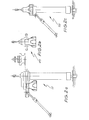
- FIG. 1 there is schematically depicted a mine drilling apparatus 10.
- the drilling apparatus 10 as an example, could be employed to drill passages to receive mine roof bolts.
- the apparatus 10 includes a support leg 11 upon which there is mounted a drive unit 12 to rotate a drill bit 13. Extending from the drive unit 12 is a control handle 14 having control levers 15 manipulated by a user of the apparatus 10.
- the handle 14 includes a yoke 16 pivotally attached to the drive unit 12 to enable pivoting of the handle 14 about the axis 17.
- the handle 14 also includes a valve assembly 18 operated by the control levers 15.
- the control levers 15 operate linkages 19 which extend to the valves within the valve assembly 18.
- the valve assembly 18 controls the delivery of water and air under pressure to the drive unit 12 and leg 11. More particularly, the valve assembly 18 is provided with a water inlet 20 and an air inlet 21. Water is then delivered from the valve assembly 18 via the yoke 16 to drive unit 12 so that water for lubrication and cooling purposes may be delivered to the drill bit 13.
- the yoke 16 may be also employed to deliver air to the leg 11.
- valve assembly 18 extending from the valve assembly 18 is a conduit 22 joining the passage 23 with the motor 24.
- the control levers 15 manipulate the rods 19 to actuate the valves within the valve assembly 18.
- the valves within the valve assembly 18 may be of a simple on-off construction or of a variable resistance type so that the flow rate of water or air may be varied.
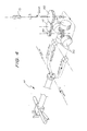
- the drive unit 12 includes the motor 24 and a gearbox 25.
- the motor 24 is more fully depicted in Figure 3 and includes a main hollow body 26 formed of plastics material such as nylon.
- the body 26 is generally hollow so as to define a crankcase 27 from which there extends passages 28.
- the passages 28 are of circular configuration and are adapted to receive metal cylinders 29.
- Reciprocally mounted within each cylinder 29 is a piston 30 while closing one end of each cylinder 19 is a head 31.
- Each head 31 has a cavity within where the cylinder 29 is received.
- the pistons 30 are arranged in pairs with the pistons of each pair being connected by a piston rod 32.
- Each piston rod 32 has a slot 33 extending generally transverse to the longitudinal axis of the pistons 30.
- the cylinders 29 are so arranged that the pistons 30 reciprocate along perpendicular axes.
- Each piston 30, its associated cylinder 29 and head 31 co-operate to define a variable volume working space to which air under pressure is delivered to cause reciprocation of the associated piston 30.
- the slots 33 intersect to define an aperture which rotates about a central axis extending normal to the longitudinal axes of both pairs of pistons 30 as well as through the intersection thereof.
- Rotatably supported by the housing 26 is a valve member 34 which also forms the drive output for the motor 23.
- the valve member 34 has a main body 35 which is rotated about the axis 36 defined by the passage 37 formed in the body 26.
- a driven shaft 38 Extending from the valve body 35 is a driven shaft 38 which is received within the recess defined by the intersection of the slots 33.
- the shaft 38 is fixed to the valve body 35 eccentrically relative to the axis 36.
- the valve body 35 is caused to rotate about the axis 36.
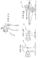
- Concentric with the axis 36 is a shaft 39 provided with a gear 40 meshingly engaged with a gear 41 (see Fig. 4).
- the gear 41 is meshingly engaged with a further gear 42 coupled to the drill bit 13.
- the valve body 35 is provided with valve passages 43, 44, 45 and 46 which provide for the passage of air under pressure to the working space defined by the pistons 30, their associated cylinders 29 and heads 31.
- the passages 44 and 45 could be used as inlet passages for air under pressure, depending on the direction of travel of the motor 24, and the passages 43 and 46 used as exhaust passages.
- the passages 43 and 46 are selectively aligned with passages 57 extending to the heads 31 for the inlet of air under pressure as well as the ducting of exhaust air from the working space, by being angularly displaced about the valve body 35 relative to the position of the shaft 38.
- the cylinders 29 are provided with a plurality of passages 47 which allow for the escape of some exhaust air into the interior of the body 26 as the top of the piston passes the passages 47.
- the motor 24 may also be used with other pieces of mining equipment as best seen in Figure 2.
- the motor 24 could be used to drive a winch 48, a portable hand-borer 49, a horizontal borer 50, a roof bolter 51 or 52, a multi-purpose drive assembly 53 or a pump 54.
- the body 26 of the motor 24 may be formed of any suitable material but is preferably formed of plastics material such as nylon.
- the wearing parts, such as the cylinders 29 would be formed of any suitable material, preferably an appropriate metal.
- other portions of the drilling apparatus 12 may also be formed of plastics material in order to reduce the weight thereof.
- the gearbox housing 55 and its associated cover 56 may also be formed of plastics material.
- the heads 31 may also be formed of plastics material, such as nylon.
- the body 26 is provided with planar faces 58 through which the passages 28 pass.
- the faces 58 are parallel to the axis 36, and are arranged in parallel opposing pairs.
- the body also has a cylindrical surface 59 enabling mounting of the motor 24 in the appropriate apparatus.
- the surface 59 is co-axial with respect to the axis 36.
- Extending through the surface 59 are a plurality of passages to deliver air to, and duct air from the passages 43 to 46.
- the leg 11 is provided with a double acting ram 57 to raise and lower the drill bit 13 upon supply of air or water under pressure.
Landscapes
- Engineering & Computer Science (AREA)
- Mechanical Engineering (AREA)
- General Engineering & Computer Science (AREA)
- Earth Drilling (AREA)
- Drilling And Boring (AREA)
- Compressors, Vaccum Pumps And Other Relevant Systems (AREA)
- Exhaust Gas After Treatment (AREA)
Applications Claiming Priority (2)
| Application Number | Priority Date | Filing Date | Title |
|---|---|---|---|
| AUPH574486 | 1986-05-05 | ||
| AU5744/86 | 1986-05-05 |
Publications (2)
| Publication Number | Publication Date |
|---|---|
| EP0245080A2 true EP0245080A2 (de) | 1987-11-11 |
| EP0245080A3 EP0245080A3 (de) | 1988-09-21 |
Family
ID=3771601
Family Applications (1)
| Application Number | Title | Priority Date | Filing Date |
|---|---|---|---|
| EP87304013A Withdrawn EP0245080A3 (de) | 1986-05-05 | 1987-05-05 | Motorzusammenbau |
Country Status (8)
| Country | Link |
|---|---|
| US (1) | US4829879A (de) |
| EP (1) | EP0245080A3 (de) |
| JP (1) | JPS6325301A (de) |
| CN (1) | CN1008385B (de) |
| BR (1) | BR8702276A (de) |
| IN (1) | IN167155B (de) |
| MY (1) | MY101732A (de) |
| ZA (1) | ZA873207B (de) |
Families Citing this family (1)
| Publication number | Priority date | Publication date | Assignee | Title |
|---|---|---|---|---|
| EP3074630A4 (de) * | 2013-11-27 | 2017-07-12 | George Konrad | Mehrkolbenmotor/-pumpe |
Family Cites Families (15)
| Publication number | Priority date | Publication date | Assignee | Title |
|---|---|---|---|---|
| US394684A (en) * | 1888-12-18 | Rotary engine | ||
| US1778238A (en) * | 1926-01-11 | 1930-10-14 | James B Tuthill | Pump |
| FR838777A (fr) * | 1938-06-01 | 1939-03-15 | Moteur thermique | |
| US2320571A (en) * | 1941-03-13 | 1943-06-01 | Sullivan Machinery Co | Motor |
| DE732376C (de) * | 1941-09-14 | 1943-03-01 | Weber Franz Josef | Brennkraftmaschine mit unmittelbarem Antrieb des Kolbens durch den rotierenden Kurbelzapfen |
| US3002504A (en) * | 1959-05-27 | 1961-10-03 | Clarence R Taylor | Fluid motor |
| US3053194A (en) * | 1960-11-25 | 1962-09-11 | Chamberlain Corp | Enclosed liquid pump |
| US3174436A (en) * | 1962-11-23 | 1965-03-23 | Seeger Wanner Corp | Radial pump |
| US3703125A (en) * | 1971-08-05 | 1972-11-21 | Richard S Pauliukonis | Plastic actuating cylinder |
| US3977303A (en) * | 1972-04-03 | 1976-08-31 | Exxon Research And Engineering Company | Engines and compressors |
| US3979910A (en) * | 1973-04-16 | 1976-09-14 | Canada Wire And Cable Limited | Closed circuit hydraulic control system |
| US4050544A (en) * | 1974-05-01 | 1977-09-27 | Kalyan Jagdish C | Lubrication system for an air motor |
| US4316705A (en) * | 1979-11-30 | 1982-02-23 | Tecumseh Products Company | Housing assembly for split crankcase radial compressor |
| US4339988A (en) * | 1980-04-08 | 1982-07-20 | Ford Motor Company | Free eccentric reciprocating piston device |
| US4478132A (en) * | 1983-06-16 | 1984-10-23 | Braddock Elijah Y | Rotary motor |
-
1987
- 1987-05-05 MY MYPI87000579A patent/MY101732A/en unknown
- 1987-05-05 ZA ZA873207A patent/ZA873207B/xx unknown
- 1987-05-05 BR BR8702276A patent/BR8702276A/pt unknown
- 1987-05-05 EP EP87304013A patent/EP0245080A3/de not_active Withdrawn
- 1987-05-05 CN CN87103877A patent/CN1008385B/zh not_active Expired
- 1987-05-05 US US07/046,079 patent/US4829879A/en not_active Expired - Fee Related
- 1987-05-06 JP JP62109080A patent/JPS6325301A/ja active Pending
- 1987-05-11 IN IN380/CAL/87A patent/IN167155B/en unknown
Also Published As
| Publication number | Publication date |
|---|---|
| MY101732A (en) | 1992-01-17 |
| EP0245080A3 (de) | 1988-09-21 |
| JPS6325301A (ja) | 1988-02-02 |
| BR8702276A (pt) | 1988-02-17 |
| ZA873207B (en) | 1987-10-28 |
| IN167155B (de) | 1990-09-08 |
| CN87103877A (zh) | 1987-12-09 |
| US4829879A (en) | 1989-05-16 |
| CN1008385B (zh) | 1990-06-13 |
Similar Documents
| Publication | Publication Date | Title |
|---|---|---|
| US6880645B2 (en) | Pneumatic rotary tool | |
| KR101684930B1 (ko) | 원형 크랭크실이 구비된 더블 피스톤 항타기 | |
| US4645428A (en) | Radial piston pump | |
| US4406595A (en) | Free piston pump | |
| US3990522A (en) | Rotary percussion drill | |
| US3223181A (en) | Vibrationless air hammer assembly | |
| US2243978A (en) | Rotary hydraulic intensifier | |
| US4597717A (en) | Two-stage fluid pump | |
| EP0245080A2 (de) | Motorzusammenbau | |
| US3307638A (en) | Rock drill drive | |
| CA1167332A (en) | Pneumatic motor for rock drills and the like | |
| AU593644B2 (en) | Motor assembly | |
| WO1983003640A1 (en) | Portable air compressor | |
| US4496023A (en) | Pneumatically operated impact tool | |
| US669234A (en) | Motor. | |
| US2512763A (en) | Hydropneumatic motor | |
| US3056390A (en) | Internal combustion percussion tools and hammer pistons for such tools | |
| US2092920A (en) | Air pump | |
| KR100416942B1 (ko) | 기체 압축 시스템 | |
| CN2363040Y (zh) | 电动凿岩机 | |
| CN220133885U (zh) | 凿岩机 | |
| US2026479A (en) | Compressor | |
| US2283047A (en) | Fluid machine and hammer | |
| US800224A (en) | Pneumatic drill. | |
| EP0070145A1 (de) | Tragbare Antriebsvorrichtung und Werkzeuge |
Legal Events
| Date | Code | Title | Description |
|---|---|---|---|
| PUAI | Public reference made under article 153(3) epc to a published international application that has entered the european phase |
Free format text: ORIGINAL CODE: 0009012 |
|
| AK | Designated contracting states |
Kind code of ref document: A2 Designated state(s): AT BE CH DE ES FR GB GR IT LI LU NL SE |
|
| PUAL | Search report despatched |
Free format text: ORIGINAL CODE: 0009013 |
|
| AK | Designated contracting states |
Kind code of ref document: A3 Designated state(s): AT BE CH DE ES FR GB GR IT LI LU NL SE |
|
| 17P | Request for examination filed |
Effective date: 19890321 |
|
| 17Q | First examination report despatched |
Effective date: 19891020 |
|
| STAA | Information on the status of an ep patent application or granted ep patent |
Free format text: STATUS: THE APPLICATION IS DEEMED TO BE WITHDRAWN |
|
| 18D | Application deemed to be withdrawn |
Effective date: 19910430 |
|
| RIN1 | Information on inventor provided before grant (corrected) |
Inventor name: SANTA, JOSE LUIS |