EP0245057B1 - Heliumkühlapparat - Google Patents
Heliumkühlapparat Download PDFInfo
- Publication number
- EP0245057B1 EP0245057B1 EP87303959A EP87303959A EP0245057B1 EP 0245057 B1 EP0245057 B1 EP 0245057B1 EP 87303959 A EP87303959 A EP 87303959A EP 87303959 A EP87303959 A EP 87303959A EP 0245057 B1 EP0245057 B1 EP 0245057B1
- Authority
- EP
- European Patent Office
- Prior art keywords
- helium
- heat
- liquid
- heat exchanger
- container
- Prior art date
- Legal status (The legal status is an assumption and is not a legal conclusion. Google has not performed a legal analysis and makes no representation as to the accuracy of the status listed.)
- Expired
Links
- 239000001307 helium Substances 0.000 title claims description 101
- 229910052734 helium Inorganic materials 0.000 title claims description 101
- SWQJXJOGLNCZEY-UHFFFAOYSA-N helium atom Chemical compound [He] SWQJXJOGLNCZEY-UHFFFAOYSA-N 0.000 title claims description 65
- 238000001816 cooling Methods 0.000 title claims description 43
- 239000003507 refrigerant Substances 0.000 claims description 25
- 239000007788 liquid Substances 0.000 claims description 20
- 239000011295 pitch Substances 0.000 claims description 18
- 239000007789 gas Substances 0.000 claims description 11
- 238000002474 experimental method Methods 0.000 description 4
- 238000002347 injection Methods 0.000 description 4
- 239000007924 injection Substances 0.000 description 4
- 238000011084 recovery Methods 0.000 description 3
- IJGRMHOSHXDMSA-UHFFFAOYSA-N Atomic nitrogen Chemical compound N#N IJGRMHOSHXDMSA-UHFFFAOYSA-N 0.000 description 2
- 238000001704 evaporation Methods 0.000 description 2
- 238000003780 insertion Methods 0.000 description 2
- 230000037431 insertion Effects 0.000 description 2
- RYGMFSIKBFXOCR-UHFFFAOYSA-N Copper Chemical compound [Cu] RYGMFSIKBFXOCR-UHFFFAOYSA-N 0.000 description 1
- 230000005494 condensation Effects 0.000 description 1
- 238000009833 condensation Methods 0.000 description 1
- 239000000112 cooling gas Substances 0.000 description 1
- 229910052802 copper Inorganic materials 0.000 description 1
- 239000010949 copper Substances 0.000 description 1
- 239000012530 fluid Substances 0.000 description 1
- 238000012423 maintenance Methods 0.000 description 1
- 229910052757 nitrogen Inorganic materials 0.000 description 1
- 230000002093 peripheral effect Effects 0.000 description 1
- 229920006395 saturated elastomer Polymers 0.000 description 1
- 230000007704 transition Effects 0.000 description 1
Images


Classifications
-
- H—ELECTRICITY
- H01—ELECTRIC ELEMENTS
- H01F—MAGNETS; INDUCTANCES; TRANSFORMERS; SELECTION OF MATERIALS FOR THEIR MAGNETIC PROPERTIES
- H01F6/00—Superconducting magnets; Superconducting coils
- H01F6/04—Cooling
-
- F—MECHANICAL ENGINEERING; LIGHTING; HEATING; WEAPONS; BLASTING
- F25—REFRIGERATION OR COOLING; COMBINED HEATING AND REFRIGERATION SYSTEMS; HEAT PUMP SYSTEMS; MANUFACTURE OR STORAGE OF ICE; LIQUEFACTION SOLIDIFICATION OF GASES
- F25B—REFRIGERATION MACHINES, PLANTS OR SYSTEMS; COMBINED HEATING AND REFRIGERATION SYSTEMS; HEAT PUMP SYSTEMS
- F25B2400/00—General features or devices for refrigeration machines, plants or systems, combined heating and refrigeration systems or heat-pump systems, i.e. not limited to a particular subgroup of F25B
- F25B2400/17—Re-condensers
Definitions
- the present invention relates to a helium cooling apparatus in which gas helium in a liquid-helium container is cooled to be recondensed, and more particularly to a helium cooling apparatus in which a condensation-heat exchanger in the liquid-helium container has an improved heat transfer coefficient.
- a liquid-helium container for cooling a superconducting coil and the like is disposed adiabatically in a cryostat.
- a helium cooling apparatus is used to cool and recondense gas helium in the liquid-helium container.
- the cooling apparatus comprises a refrigerator for cooling a refrigerant, and a condensation-heat exchanger for evaporating the refrigerant to cool the gas helium.
- helium cooling apparatuses can be classified into two types. In one type, the refrigerator is incorporated in the cryostat, and the condensation-heat exchanger is located in the liquid-helium container.
- an exclusive-use cylindrical member extends from an exclusive-use port in the liquid-helium container to the outside of the cryostat.
- the heat exchanger is inserted into the helium container through the port and the cylindrical member for exclusive use.
- the refrigerator is disposed inside the cylindrical member or outside the cryostat.
- the refrigerator In maintaining the refrigerator, in the case of the first type, the refrigerator must be disassembled, repaired, and reassembled after the temperature of the helium in the liquid-helium container is raised. In this type, therefore, the refrigerator cannot be maintained with ease.
- the helium cooling apparatus can be mounted or demounted easily, without causing the liquid helium in the container to be discharged. In the second type, therefore, the refrigerator can be maintained without increasing the temperature of the helium in the helium container.
- the helium cooling apparatus of the second type has an advantage over the first type.
- the performance of the helium cooling apparatus depends on that of the refrigerator and the heat transfer coefficient of the condensation-heat exchanger. In order to improve the performance of the cooling apparatus, therefore, the heat transfer coefficient of the exchanger must be improved. Thus, the heat-transfer area of the heat exchanger is expected to be increased.
- the diameters of the port and the cylindrical member for exclusive use depend on the size of the condensation-heat exchanger. If the heat-transfer area of the heat exchanger becomes greater, therefore, the diameter of the exchanger, and hence, those of the port and the cylindrical member, are increased in proportion. Thus, the amount of heat introduced into the liquid-helium container, through the port and the cylindrical member, increases. The introduced heat lowers the thermal efficiency of the whole cooling apparatus.
- EP-A 0 145 867 discloses the use of grooved surfaces in order to improve heat transfer in the presence of two-phase fluid.
- An object of the present invention is to provide a helium cooling apparatus, in which a condensation-heat exchanger enjoys an improved heat transfer coefficient and a reduced diameter, so that a port of a liquid-helium container, through which the heat exchanger is insetted into the container, can be reduced in diameter.
- a helium cooling apparatus comprising a refrigerator for cooling a refrigerant; a transfer line for transferring the refrigerant, having a proximal end and a distal end, the transfer line connected to the refrigerator at the proximal end; a liquid-helium container having a port with a predetermined diameter and containing liquid helium; and a condensation-heat exchanger connected to the distal end of the transfer line, said heat exchanger being adapted to be inserted into the liquid-helium container through the port thereof, characterized in that the condensation-heat exchanger has a plurality of grooves formed on a heat-transfer surface thereof, so as to extend in the gravitational direction, whereby the refrigerant is supplied from the refrigerator to the exchanger through the transfer line, said refrigerant is evaporated in the heat exchanger, and condensed liquid helium adhering to the heat-transfer surface drops along the grooves when gas helium in the liquid-helium container is cooled
- the refrigerant is evaporated in the heat exchanger, so that helium gas in the liquid-helium container is cooled to be recondensed.
- the condensed liquid helium, adhering to the heat-transfer surface drops along the grooves. Accordingly, the heat-transfer surface cannot be covered with the condensed liquid helium, so that a wide heat-transfer area can be secured.
- the port of the liquid-helium container, through which the exchanger is inserted into the container need not have a large diameter. Therefore, the amount of heat entering the container through the port is very small. Since the heat exchanger is small-sized, moreover, the port for the insertion thereof need not always be an exclusive one.
- the condensation-heat exchanger according to the present invention may be used also in a liquid-helium container without an exclusive-use port.
- cryostat 2 which incorporates helium cooling apparatus I according to the present invention.
- Cryostat 2 comprises liquid-helium container II, heat-shielding plate 12, and vacuum container 13.
- Container II is filled with liquid helium 14.
- Object 15 of cooling e.g., superconducting magnet
- Heat-shielding plate 12 is cooled by liquid nitrogen, for example.
- Liquid-helium container II has port 18, to which is attached liquid-helium injection pipe 16 which opens to the outside.
- Container II is fitted with helium gas recovery pipe 17 which opens to the outside. After liquid helium 14 is put into container II, injection pipe 16 is closed. When helium 14 is evaporated by heat introduced into container II, the resulting vapor is recovered through recovery pipe 17.
- Helium cooling apparatus I comprises refrigerator 21 for cooling gas helium as a refrigerant, condensation-heat exchanger 24 for evaporating the refrigerant, thereby cooling the inside of liquid-helium container II, and transfer line 23 connecting refrigerator 21 and heat exchanger 24.
- Refrigerator 21 includes first and second cooling systems 31 and 32, both of which are closed-cycle systems.
- First cooling system 31 has three heat exchangers 33, 34 and 35.
- Exchanger 33 is connected to compressor 36.
- Outgoing line 38 which extends from compressor 36, is connected to Joule-Thomson valve 37 via heat exchangers 33, 34 and 35.
- Return line 39 which extends from transfer line 23, is connected to compressor 36 via heat exchangers 35, 34 and 33.
- the refrigerant flowing through outgoing line 38 is cooled by the refrigerant flowing through return line 39.
- the refrigerant in line 38 is cooled by second cooling system 32, which has two heat exchangers 40 and 41.
- Exchanger 40 is connected to compressor 42.
- the refrigerant flowing through outgoing line 38 is cooled further by exchangers 40 and 41.
- Transfer line 23 is composed of inner and outer pipes 43 and 44. Outgoing and return lines 38 and 39 are connected to pipes 43 and 44, respectively. Thus, the refrigerant is fed through inner pipe 43, and is evaporated by condensation-heat exchanger 24, and then returned through outer pipe 44.
- the outside diameter of transfer line 23 is smaller than the inside diameter of liquid-helium injection pipe 16.
- Condensation-heat exchanger 24 is attached to the distal end of transfer line 23.
- the outside diameter of heat exchanger 24 is substantially equal to that of line 23.
- Exchanger 24 is located in a helium gas region inside liquid-helium container II.
- Inner and outer pipes 38 and 39 of transfer line 23 terminate in a predetermined space inside heat exchanger 24. Within this space, the refrigerant is evaporated, thereby cooling a heat-transfer surface of the heat exchanger.
- exchanger 24 is formed from oxygen-free copper having a good thermal conductivity.
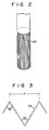
- grooves 50 are formed on the peripheral surface or heat-transfer surface of heat exchanger 24, extending in the axial or gravitational direction. These grooves will be described in detail later.
- the helium cooling apparatus of the invention cools the helium in the liquid-helium container as follows.
- liquid-helium container II When helium gas recovery pipe 17 is closed, liquid-helium container II is sealed hermetically. Meanwhile, seal member 25 is used to seal the gap between liquid-helium injection pipe 16 and transfer line 23. If container II is left as it is, in this state, the liquid helium therein is evaporated, so that the pressure inside the container increases.
- compressors 36 and 42 are actuated to drive helium cooling apparatus I.
- the refrigerant starts to flow through outgoing line 38.
- the refrigerant whose temperature is about 300 K at the start, is cooled to about 60 K by heat exchangers 33 and 40. Thereafter, it is cooled further to about 16 K by heat exchangers 34 and 41, and then to about 5 K by heat exchanger 35.
- the refrigerant is subjected to Joule-Thomson expansion by Joule-Thomson valve 37, so that its pressure is lowered to about I atm.
- the refrigerant at a pressure of about I atm.
- condensation-heat exchanger 24 a temperature of 4.2 K
- the refrigerant is evaporated by being boiled in heat exchanger 24.
- the heat-transfer surface of exchanger 24 is cooled. Accordingly, heat inside liquid-helium container II is transferred through the heat-transfer surface to exchanger 24.
- grooves 50 are formed on the heat-transfer surface so as to extend in the gravitational direction. Therefore, a wide heat-transfer area can be secured, and the liquid helium adhering to the transfer surface can drop along grooves 50. Thus, the condensation-heat transfer coefficient of the cooling device is improved considerably. The action of the liquid helium adhering to grooves 50 will be described in detail later.
- liquid-helium container II the pressure inside liquid-helium container II is kept constant.
- Liquid helium 14 does not change in quantity, and the object of cooling is cooled continuously for a long period of time.
- each groove 50 on the heat-transfer surface is triangular in shape.
- the bottom and each edge top of groove 50 are acute-angled.
- the distance between the two edge tops of each groove 50 is referred to as pitch P.
- the angle formed by the bottom of groove 50 is ⁇ l, while the angle formed by each edge top is e2. Angles ol and e2 are substantially equal.
- the inventors hereof conducted an experiment to examine the heat transfer coefficient of the condensation-heat exchanger, while variously changing pitch P and angles ol and e2.
- Fig. 4 shows an experiment result obtained with use of varying pitches.
- the curve of Fig. 4 represents the relationship between pitch P and value h/ho, where ho is the condensation-heat transfer coefficient obtained without any grooves on the heat-transfer surface, and h is the heat transfer coefficient obtained when pitch P is changed as aforesaid.
- the curve of Fig. 4 indicates a transition of transfer coefficient h on the assumption that ho is I.
- pitch P ranges from 800 to 1,200 ⁇ m
- coefficient h is about 2.5 times as high as coefficient ho.
- the heat transfer coefficient of heat exchanger II can be improved considerably by using pitch P within the aforesaid range.
- the pitch of grooves 50 ranges from 800. to 1,200 ⁇ m
- the condensed liquid helium adheres only to the bottom portion of each groove, as shown in Fig. 5. Therefore, the edge tops of each groove 50 are exposed from the liquid helium, and are in contact with the helium gas in liquid-helium container II. Accordingly, the heat-transfer surface of the grooves cannot be covered with the condensed helium, so that a wide heat-transfer area can be secured. Thus, the heat transfer coefficient of the heat-transfer surface is improved considerably.
- the inventors hereof also conducted an experiment in which angles al and 0 2 at the bottom and the edge top were changed variously, while keeping pitch P within the aforesaid range.
- the heat transfer coefficient of condensation-heat exchanger II was examined with angles ⁇ l and 02 ranging from 30 ° to 70 ° . Thereupon, it was indicated that the heat transfer coefficient is constant without regard to bottom angle ⁇ l. Thus, it is appreciated that the condensation-heat transfer coefficient cannot be influenced by the angles at the edge top or the bottom of grooves 50.
- the heat exchanger of the invention is smaller in diameter than the prior art heat exchanger.
- the port of the liquid-helium container, through which the exchanger is inserted into the container need not have a large diameter. Therefore, the amount of heat entering the container through the port is very small. Since the heat exchanger is small-sized, moreover, the port for the insertion thereof need not always be an exclusive one.
- the condensation-heat exchanger according to the present invention may be used also in a liquid-helium container without an exclusive-use port.
- each groove 50 need not always be acute-angled. Alternatively, it may be arcuate in shape, as shown in Fig. 7.
Landscapes
- Engineering & Computer Science (AREA)
- Power Engineering (AREA)
- Separation By Low-Temperature Treatments (AREA)
- Containers, Films, And Cooling For Superconductive Devices (AREA)
- Polarising Elements (AREA)
Claims (7)
Applications Claiming Priority (2)
| Application Number | Priority Date | Filing Date | Title |
|---|---|---|---|
| JP61103408A JPH0730963B2 (ja) | 1986-05-06 | 1986-05-06 | ヘリウム冷却装置 |
| JP103408/86 | 1986-05-06 |
Publications (3)
| Publication Number | Publication Date |
|---|---|
| EP0245057A2 EP0245057A2 (de) | 1987-11-11 |
| EP0245057A3 EP0245057A3 (en) | 1988-09-14 |
| EP0245057B1 true EP0245057B1 (de) | 1990-08-08 |
Family
ID=14353224
Family Applications (1)
| Application Number | Title | Priority Date | Filing Date |
|---|---|---|---|
| EP87303959A Expired EP0245057B1 (de) | 1986-05-06 | 1987-05-01 | Heliumkühlapparat |
Country Status (4)
| Country | Link |
|---|---|
| US (1) | US4756167A (de) |
| EP (1) | EP0245057B1 (de) |
| JP (1) | JPH0730963B2 (de) |
| DE (1) | DE3764158D1 (de) |
Cited By (1)
| Publication number | Priority date | Publication date | Assignee | Title |
|---|---|---|---|---|
| DE102023212894B3 (de) | 2023-12-18 | 2025-02-06 | Bruker Switzerland Ag | Vorrichtung und Verfahren zum Transfer von flüssigem Helium in einen Anwendungskryostaten |
Families Citing this family (11)
| Publication number | Priority date | Publication date | Assignee | Title |
|---|---|---|---|---|
| JPS6456153A (en) * | 1987-08-27 | 1989-03-03 | Yoshikage Oda | Low-temperature cold reserving device |
| US4796433A (en) * | 1988-01-06 | 1989-01-10 | Helix Technology Corporation | Remote recondenser with intermediate temperature heat sink |
| JPH0728531Y2 (ja) * | 1989-02-01 | 1995-06-28 | ダイキン工業株式会社 | 極低温冷凍機 |
| JP2821241B2 (ja) * | 1990-06-08 | 1998-11-05 | 株式会社日立製作所 | 液化冷凍機付きクライオスタツト |
| US5613367A (en) * | 1995-12-28 | 1997-03-25 | General Electric Company | Cryogen recondensing superconducting magnet |
| ATE290194T1 (de) * | 1997-12-12 | 2005-03-15 | Medi Physics Inc | Verfahren zum sammeln und auftauen polarisierter gase, dessen sammler und heizmanschette |
| DE10251449B4 (de) * | 2001-11-21 | 2004-12-30 | Siemens Ag | Kryostat |
| RU2505760C2 (ru) * | 2008-09-09 | 2014-01-27 | Конинклейке Филипс Электроникс, Н.В. | Теплообменник с горизонтальным оребрением для криогенного охлаждения с повторной конденсацией |
| CN109945596B (zh) * | 2019-03-05 | 2024-01-16 | 中国工程物理研究院激光聚变研究中心 | 温度梯度型低温环境制备装置 |
| JP7530185B2 (ja) * | 2020-02-25 | 2024-08-07 | 住友重機械工業株式会社 | 極低温冷凍機および極低温システム |
| CN114171281B (zh) * | 2022-02-14 | 2022-05-17 | 宁波健信核磁技术有限公司 | 一种超导磁体加热系统 |
Family Cites Families (5)
| Publication number | Priority date | Publication date | Assignee | Title |
|---|---|---|---|---|
| US2831549A (en) * | 1954-08-31 | 1958-04-22 | Westinghouse Electric Corp | Isolation trap |
| US4159739A (en) * | 1977-07-13 | 1979-07-03 | Carrier Corporation | Heat transfer surface and method of manufacture |
| US4543794A (en) * | 1983-07-26 | 1985-10-01 | Kabushiki Kaisha Toshiba | Superconducting magnet device |
| AU548348B2 (en) * | 1983-12-21 | 1985-12-05 | Air Products And Chemicals Inc. | Finned heat exchanger |
| JPS60259870A (ja) * | 1984-06-05 | 1985-12-21 | 株式会社東芝 | 磁気冷凍装置 |
-
1986
- 1986-05-06 JP JP61103408A patent/JPH0730963B2/ja not_active Expired - Lifetime
-
1987
- 1987-04-28 US US07/043,445 patent/US4756167A/en not_active Expired - Lifetime
- 1987-05-01 EP EP87303959A patent/EP0245057B1/de not_active Expired
- 1987-05-01 DE DE8787303959T patent/DE3764158D1/de not_active Expired - Lifetime
Cited By (3)
| Publication number | Priority date | Publication date | Assignee | Title |
|---|---|---|---|---|
| DE102023212894B3 (de) | 2023-12-18 | 2025-02-06 | Bruker Switzerland Ag | Vorrichtung und Verfahren zum Transfer von flüssigem Helium in einen Anwendungskryostaten |
| DE102023212894B8 (de) | 2023-12-18 | 2025-04-30 | Bruker Switzerland Ag | Vorrichtung und Verfahren zum Transfer von flüssigem Helium in einen Anwendungskryostaten |
| EP4575352A1 (de) | 2023-12-18 | 2025-06-25 | Bruker Switzerland AG | Vorrichtung und verfahren zum transfer von flüssigem helium in einen anwendungskryostaten |
Also Published As
| Publication number | Publication date |
|---|---|
| DE3764158D1 (de) | 1990-09-13 |
| US4756167A (en) | 1988-07-12 |
| JPH0730963B2 (ja) | 1995-04-10 |
| EP0245057A2 (de) | 1987-11-11 |
| JPS62261866A (ja) | 1987-11-14 |
| EP0245057A3 (en) | 1988-09-14 |
Similar Documents
| Publication | Publication Date | Title |
|---|---|---|
| EP0245057B1 (de) | Heliumkühlapparat | |
| CA1285781C (en) | Cryogenic recondenser with remote cold box | |
| KR0175113B1 (ko) | 피냉각물을 극저온으로 냉각하는 극저온 냉각장치 | |
| US6812601B2 (en) | Superconductor rotor cooling system | |
| US5701751A (en) | Apparatus and method for actively cooling instrumentation in a high temperature environment | |
| US3430455A (en) | Thermal switch for cryogenic apparatus | |
| US6389821B2 (en) | Circulating cryostat | |
| CA1312209C (en) | Remote recondenser with intermediate temperature heat sink | |
| US20070089432A1 (en) | Cryostat configuration with cryocooler | |
| CN1795602A (zh) | 带有超导绕组及温差环流冷却装置的超导电机设备 | |
| US5113165A (en) | Superconductive magnet with thermal diode | |
| JPS607396B2 (ja) | 超電導装置 | |
| JPH08222429A (ja) | 極低温装置 | |
| JPS6294769A (ja) | 二段熱カツプリング | |
| Green | The integration of liquid cryogen cooling and cryocoolers with superconducting electronic systems | |
| USRE33878E (en) | Cryogenic recondenser with remote cold box | |
| EP0937953A1 (de) | Kältemaschine | |
| JP4595121B2 (ja) | 機械式冷凍機とジュール・トムソン膨張を用いた極低温冷凍装置 | |
| US20090275476A1 (en) | Cryostat assembly | |
| Leupold et al. | Subcooled superfluid helium cryostat for a hybrid magnet system | |
| US4030900A (en) | Cooling device | |
| JP3465195B2 (ja) | クライオポンプ | |
| Ishige et al. | 4. 2K Refrigerator for SQUID Magnetometer | |
| JPS6138363A (ja) | ヘリウム冷凍装置 | |
| CA1133382A (en) | Cryostat with serviceable refrigerator |
Legal Events
| Date | Code | Title | Description |
|---|---|---|---|
| PUAI | Public reference made under article 153(3) epc to a published international application that has entered the european phase |
Free format text: ORIGINAL CODE: 0009012 |
|
| AK | Designated contracting states |
Kind code of ref document: A2 Designated state(s): DE GB NL |
|
| 17P | Request for examination filed |
Effective date: 19880204 |
|
| PUAL | Search report despatched |
Free format text: ORIGINAL CODE: 0009013 |
|
| AK | Designated contracting states |
Kind code of ref document: A3 Designated state(s): DE GB NL |
|
| 17Q | First examination report despatched |
Effective date: 19890201 |
|
| GRAA | (expected) grant |
Free format text: ORIGINAL CODE: 0009210 |
|
| AK | Designated contracting states |
Kind code of ref document: B1 Designated state(s): DE GB NL |
|
| REF | Corresponds to: |
Ref document number: 3764158 Country of ref document: DE Date of ref document: 19900913 |
|
| PLBE | No opposition filed within time limit |
Free format text: ORIGINAL CODE: 0009261 |
|
| STAA | Information on the status of an ep patent application or granted ep patent |
Free format text: STATUS: NO OPPOSITION FILED WITHIN TIME LIMIT |
|
| 26N | No opposition filed | ||
| PGFP | Annual fee paid to national office [announced via postgrant information from national office to epo] |
Ref country code: DE Payment date: 19990507 Year of fee payment: 13 |
|
| PGFP | Annual fee paid to national office [announced via postgrant information from national office to epo] |
Ref country code: NL Payment date: 19990531 Year of fee payment: 13 |
|
| PG25 | Lapsed in a contracting state [announced via postgrant information from national office to epo] |
Ref country code: NL Free format text: LAPSE BECAUSE OF NON-PAYMENT OF DUE FEES Effective date: 20001201 |
|
| NLV4 | Nl: lapsed or anulled due to non-payment of the annual fee |
Effective date: 20001201 |
|
| PG25 | Lapsed in a contracting state [announced via postgrant information from national office to epo] |
Ref country code: DE Free format text: LAPSE BECAUSE OF NON-PAYMENT OF DUE FEES Effective date: 20010301 |
|
| PGFP | Annual fee paid to national office [announced via postgrant information from national office to epo] |
Ref country code: GB Payment date: 20010425 Year of fee payment: 15 |
|
| REG | Reference to a national code |
Ref country code: GB Ref legal event code: IF02 |
|
| PG25 | Lapsed in a contracting state [announced via postgrant information from national office to epo] |
Ref country code: GB Free format text: LAPSE BECAUSE OF NON-PAYMENT OF DUE FEES Effective date: 20020501 |
|
| GBPC | Gb: european patent ceased through non-payment of renewal fee |
Effective date: 20020501 |