EP0244921A2 - Method for recovering platinum in a nitric acid plant - Google Patents
Method for recovering platinum in a nitric acid plant Download PDFInfo
- Publication number
- EP0244921A2 EP0244921A2 EP19870201149 EP87201149A EP0244921A2 EP 0244921 A2 EP0244921 A2 EP 0244921A2 EP 19870201149 EP19870201149 EP 19870201149 EP 87201149 A EP87201149 A EP 87201149A EP 0244921 A2 EP0244921 A2 EP 0244921A2
- Authority
- EP
- European Patent Office
- Prior art keywords
- gauze
- recovery
- catalyst
- platinum
- wire diameter
- Prior art date
- Legal status (The legal status is an assumption and is not a legal conclusion. Google has not performed a legal analysis and makes no representation as to the accuracy of the status listed.)
- Granted
Links
Images


Classifications
-
- C—CHEMISTRY; METALLURGY
- C22—METALLURGY; FERROUS OR NON-FERROUS ALLOYS; TREATMENT OF ALLOYS OR NON-FERROUS METALS
- C22B—PRODUCTION AND REFINING OF METALS; PRETREATMENT OF RAW MATERIALS
- C22B11/00—Obtaining noble metals
- C22B11/10—Obtaining noble metals by amalgamating
- C22B11/12—Apparatus therefor
-
- C—CHEMISTRY; METALLURGY
- C22—METALLURGY; FERROUS OR NON-FERROUS ALLOYS; TREATMENT OF ALLOYS OR NON-FERROUS METALS
- C22B—PRODUCTION AND REFINING OF METALS; PRETREATMENT OF RAW MATERIALS
- C22B7/00—Working up raw materials other than ores, e.g. scrap, to produce non-ferrous metals and compounds thereof; Methods of a general interest or applied to the winning of more than two metals
- C22B7/009—General processes for recovering metals or metallic compounds from spent catalysts
-
- C—CHEMISTRY; METALLURGY
- C22—METALLURGY; FERROUS OR NON-FERROUS ALLOYS; TREATMENT OF ALLOYS OR NON-FERROUS METALS
- C22B—PRODUCTION AND REFINING OF METALS; PRETREATMENT OF RAW MATERIALS
- C22B11/00—Obtaining noble metals
- C22B11/02—Obtaining noble metals by dry processes
- C22B11/021—Recovery of noble metals from waste materials
- C22B11/026—Recovery of noble metals from waste materials from spent catalysts
- C22B11/028—Recovery of noble metals from waste materials from spent catalysts using solid sorbents, e.g. getters or catchment gauzes
-
- C—CHEMISTRY; METALLURGY
- C22—METALLURGY; FERROUS OR NON-FERROUS ALLOYS; TREATMENT OF ALLOYS OR NON-FERROUS METALS
- C22B—PRODUCTION AND REFINING OF METALS; PRETREATMENT OF RAW MATERIALS
- C22B7/00—Working up raw materials other than ores, e.g. scrap, to produce non-ferrous metals and compounds thereof; Methods of a general interest or applied to the winning of more than two metals
- C22B7/001—Dry processes
-
- Y—GENERAL TAGGING OF NEW TECHNOLOGICAL DEVELOPMENTS; GENERAL TAGGING OF CROSS-SECTIONAL TECHNOLOGIES SPANNING OVER SEVERAL SECTIONS OF THE IPC; TECHNICAL SUBJECTS COVERED BY FORMER USPC CROSS-REFERENCE ART COLLECTIONS [XRACs] AND DIGESTS
- Y02—TECHNOLOGIES OR APPLICATIONS FOR MITIGATION OR ADAPTATION AGAINST CLIMATE CHANGE
- Y02P—CLIMATE CHANGE MITIGATION TECHNOLOGIES IN THE PRODUCTION OR PROCESSING OF GOODS
- Y02P10/00—Technologies related to metal processing
- Y02P10/20—Recycling
Definitions
- Nitric acid is produced commercially by passing ammonia and air over an oxidation catalyst which is usually a gauze woven from platinum-rhodium alloy wire.
- an oxidation catalyst which is usually a gauze woven from platinum-rhodium alloy wire.
- the temperature of gas leaving the gauze ranges from about 810°C to about 960°C., most often above 850°C.
- platinum is slowly lost from the gauze, possibly in the form of the more volatile oxides.
- Rhodium is also lost, but this is not so severe a problem.
- the rate of loss depends upon the type of plant. Typically, for each ton of ammonia converted, a high pressure plant will lost more than one gram of platinum, while lower pressure plants will lose less. Even though the rate of catalyst loss is slow when expressed in terms of weight, the cost is usually. quite substantial. In many operations, the cost of platinum lost during production has been said to be the second largest expense of the operation, exceeded only by the cost of ammonia feedstock.
- a variety of alloying elements have been selected, mainly for their ability to improve the mechanical properties of palladium.
- Typical commercial palladium alloys have contained about 80% palladium and 20% gold by weight.
- the recovery alloys are usually employed in the form of multiple sheets of woven gauze but knitted meshes or other foraminous elements can also be used.
- the recovery gauze is usually placed as close as possible to the catalyst gauze, often within a few millimetres, usually no more than 10 mm. Since the catalyst gauze in a nitric acid plant is changed regularly on a schedule of from about every 35 to every 270 days, depending on plant design, as a practical matter, the recovery gauze is usually replaced when the catalyst gauze is changed, although it is possible to replace it less frequently.
- Application No. 82304173.6 claims a foraminate element for the recovery of platinum and/or rhodium lost from a platinum-containing catalyst, said element being fabricated from palladium or an alloy comprising a major proportion of palladium, characterized in that the initial product of mesh size (expressed as the number of wires per centimetre, N) and wire diameter in centimetres (d w ) for said element is greater than 0.3 or, in the case when the alloy comprises a minor proportion of nickel, greater than 02.
- Application No. 82304173.6 also claims a method for recovering platinum lost from a platinum-containing catalyst gauze in a nitric acid plant, wherein the catalyst gauze is replaced periodically, the period being the "catalyst gauze cycle length", wherein at least one recovery gauze sheet consisting of an alloy comprising a major proportion of palladium is placed adjacent to the catalyst gauze downstream of the catalyst gauze, characterized in that the mesh size N (expressed as the number of wires per centimetre) and wire diameter d w (in centimetres) of the recovery gauze are chosen such that the average recovery efficiency over the catalyst gauze cycle length exceeds 1 -exp (-3.22/L " , ⁇ '), the average recovery efficiency 7l being as calculated according to the formula wherein " ⁇ ” is the volumetric void fraction of the gauze, “Sc” is the Schmidt number for the diffusion of oxidized platinum in the effluent from the catalyst gauze; “Re” is the Reynolds number based on the wire diameter and average velocity of the process stream just up
- Application No. 82304173.6 further claims a method of making a gauze for recovery of platinum lost from a platinum-containing catalyst in a nitric acid plant, comprising
- the optimum cycle length of a recovery gauze is a function, inter alia, of its recovery efficiency.
- the ability to adjust the recovery efficiency thus provides a means for tailoring the cycle length to suit the plant in which the gauze is to be used.
- a method for recovering platinum lost from a platinum-containing catalyst gauze in a nitric acid plant wherein the catalyst gauze is replaced periodically, the period being the catalyst gauze cycle length "Tp", wherein at least one recovery gauze consisting of palladium or an alloy comprising a major proportion of palladium is placed adjacent to the catalyst gauze downstream of the catalyst gauze, characterized in that the mesh size and wire diameter of the recovery gauze are chosen such that the predicted recovery gauze cycle length "T", as calculated from the formula is in the range of from 0.9 Tp to 1.1 Tp, wherein "W” is the weight in grams per square meter of the recovery gauze sheet, “b m “ is the weight in grams of platinum lost from the catalyst gauze per tonne of nitrogen (in ammonia) converted, “L m “ is the weight in tonnes of nitrogen (in ammonia) passed over each square meter of the catalyst gauze per day, and “ ⁇ ” is the recovery efficiency of the recovery gauze sheet as calculated according to the formula
- the efficiency of the recovery gauze ( 71 ) exceeds 1 - exp(-3.22/L m • 7 ); wherein L m is as defined above.
- the initial product of the mesh and wire diameter exceeds 02 for gauzes containing a major proportion of palladium and a minor proportion of nickel.
- the initial product of the mesh and the wire diameter will be in the range of from 02 to 0.9.
- the initial product of the mesh and wire diameter should be at least 3.0 and preferably in the range of from 0.3 to 0.9, more preferably from 0.35 to 0.9.
- the mesh N be in the range of from 3.9 to 31.5 cm-' (10 to 80 in-'), d w is in the range of from 0.0076 to 0.229 cm (0.003 to 0.090 inches), and their respective values are such that the initial product of N and d w is greater than 02.
- the initial instantaneous recovery efficiencies (71), that is the percentage of platinum in the stream that is recovered by a single gauze having high palladium content, may be estimated by the use of the quasi- empirical formula wherein " ⁇ " is the volumetric void fraction of the gauze, which is preferably less than 0.76, and more preferably less than 0.685, but greater than 0; "Sc” is the Schmidt number for the diffusion of oxidized platinum in the effluent from the catalyst gauze, which is usually between .8 and 1.0; “Re” is the Reynolds number based on the wire diameter and average velocity of the process stream just upstream of the recovery gauze i.e., where "G” is the mass velocity of the gaseous stream fed to the catalyst; “ ⁇ ” is the dynamic viscosity of the effluent from the catalyst gauze; typically, the Reynolds number will be between 10 and 200, most often from 20 to 50; “C” is the appropriate mass transfer correlation coefficient for the geometry
- N is the mesh or number of wires per centimeter (0.394 inch)
- equation 1 will work adequately with values for "C” of .94 and for "m” of .7 for the screens, reactors and flow conditions described in this application, if the values of Schmidt number and viscosity given below are used, even though the diffusing species may not necessarily be platinum oxide.
- efficiency vs. wire diameter graphs similar to Figures 1, 2 and 3 can be constructed using formula 1.
- the properties of the gas streams vary only by small amounts over the temperature ranges encountered in practice of from about 810° to about 960 0 , so that properties at 900°C can be used with only slight error.
- the concentration of the feed to the catalyst is .normally regulated to between 10.0 to 10.5 m/o (mole percent) ammonia and 90.0 to 89.5 m /o air, so the composition of the reaction products from the catalyst gauze remains constant, so that physical properties in that range can be used: In these ranges, the Schmidt No. is about .9 - .95 for diffusion of platinum oxide vapours in air and the dynamic viscosity of the gas is about 4.2 x 10- 6 Pa.s (about 4.2 x 10- 5 poise).
- the efficiency is determined primarily by the mesh "N", and wire diameter "d w ", for a given nitrogen loading “L m “, where the nitrogen loading “L m “ is the number of tonnes of nitrogen (in ammonia) passed through each square meter of the catalyst gauze per day (or "L", where the nitrogen loading “L” is the number of short tons of nitrogen (in ammonia) passed through each square meter of the catalyst gauze per day).
- efficiency can be plotted as a function of wire diameter for a variety of mesh sizes.
- void fraction can be shown parametrically on the same graph, so that efficiency and the void fraction can be determined simultaneously for each given combination of wire diameter and mesh.
- the pressure drop through the gauze can be estimated using known correlations.
- the volumetric void fraction (71) be between about 0.76 and about 0.5.
- Volumetric void fractions from about 0.5 down to about 0.3 can provide even better recovery efficiencies, but care must be exercised to properly support the recovery gauze so that it is not damaged or displaced by the force of the stream of gas passing through it.
- volumetric void fractions between about 0.685 and about 0.5 will provide an excellent combination of especially high recovery efficiency with acceptable pressure drop.
- Void fractions of about 0.3 and lower can be used to provide extremely high recovery efficiencies, but many existing plants would require modification of the gauze support to withstand and properly distribute the resulting force of the stream on the gauze. In some circumstances, the cost of power due to pressure drop may also be of some significance. However, in practice, it is normally sufficient to limit consideration to volumetric void fractions above about 0.3 and preferably in the range of from about 0.5 to about 0.76. The most preferred range of void fractions is from about 0.5 to about 0.685.
- the method of fabricating gauzes according to the present invention is easily accomplished by plotting at least a portion of the appropriate efficiency vs. wire diameter graph for the conditions, such as temperature, pressure and nitrogen loading of the plant under consideration. Then the catalyst cycle length line can be plotted on this graph using the following procedure, such that if a mesh and wire diameter combination near the catalyst cycle length line is chosen, the average recovery efficiency of the gauze over the catalyst cycle (n ) will be within the range of this invention.
- the catalyst cycle length line is plotted by determining which gauzes will yield acceptable efficiencies ( ⁇ ) by drawing a horizontal line corresponding to the minimum acceptable efficiency across the appropriate efficiency vs. wire diameter graph, such as Figures 1-3. Then the appropriate recovery gauze cycle lengths "T” for a variety of mesh sizes and wire diameters above this horizontal line are determined using the formula wherein "W” is the weight of each square meter of the recovery gauze sheet and "b m " is the amount of platinum lost per tonne of ammonia processed (or “b” is the amount of platinum lost per ton of ammonia processed). In accordance with the model of the present invention, the rate of platinum recovery is approximately constant at least until the recovery gauze cycle length has been reached, but decreases rapidly thereafter.
- “W” in general is . "6" for a single linen weave can be determined from Figure 4.
- the weight may be calculated in a similar fashion from first principles or if necessary may be determined empirically. If no better data is available from the plant history or the history of a similar plant, "b” may be estimated from Figure 5, presenting loss of platinum per ton of nitrogen processed as a function of nitrogen loading on the catalyst gauze.
- the catalyst cycle length line is drawn connecting the points where the recovery gauze cycle length "T" coincides with the planned catalyst cycle length of the plant, "Tp". Then a gauze giving an acceptable efficiency and pressure drop is chosen near this line.
- the minimum weight gauze which will both yield an efficiency within the range of this invention and match the planned catalyst cycle length of the plant should be chosen. It is preferred that the gauze sheets used have a weight of less than 686 g/m 2 (2.05 Troy ounces per square foot) or more preferably less than 636 g/m 2 (1.9 Troy ounces per square foot).
- the recovery gauze cycle length of the n th gauze is determined by using the formula where " ⁇ i" is the recovery efficiency of the it"recovery gauze sheet and Wn is the weight of the nth gauze.
- ⁇ i is the recovery efficiency of the it"recovery gauze sheet
- Wn is the weight of the nth gauze.
- the first sheet of the pack should be designed as described previously, so that it will have an average recovery efficiency over the catalyst cycle within an acceptable range, and preferably greater than 1 -exp (-3.22/L m e 1 ), i e. greater than 1 -exp (-3.45/Lo').
- the recovery gauze cycle length for this first gauze sheet will be in the range of from about nine-tenths to eleven-tenths of the planned catalyst gauze cycle length for the plant.
- FIG. 6 is a graph illustrating the average recovery efficiencies obtainable over the catalyst cycle length with the preferred gauzes of the present invention as a function of nitrogen loading, as compared to efficiencies reported in the prior art.
- recovery gauzes almost always contain a major proportion of palladium or gold and minor additions of other alloying elements which improve mechanical properties.
- major proportion of palladium it is meant that the recovery gauze contains at least about 70% palladium by weight.
- the recovery gauzes will contain at least about 80% palladium and more preferably 90%.
- the most preferred recovery gauzes contain at least about 95% palladium by weight.
- the most widely used alloy has been an alloy containing 80% palladium and 20% gold. While this alloy has found wide use, alternatives have been sought, since inclusion of gold greatly increases the cost of the gauze.
- Other alloying elements for palladium include other platinum group metals, nickel, manganese, chromium, carbon, boron, and the like.
- Particularly useful palladium alloys include palladium/gold, palladium/platinum, palladium/nickel, palladium/copper, palladium/ruthenium, and palladium/silver.
- gauzes containing a major proportion of gold and a minor proportion of a platinum group metal have been suggested, since it has been reported that gold does not volatilize to the same extent as palladium. The ability of these gold-rich alloys to withdraw platinum seems to be somewhat less than the ability of palladium-rich alloys.
- the mechanical properties of the gold-rich alloys may be improved by adding metals which have a greater affinity for platinum than for oxygen, such as tantalum, niobium, and the like.
- suitable alloying elements include titanium, zirconium, chromium, nickel, manganese, and the like.
- the preferred alloys are palladium/gold and palladium/nickel alloys, particularly alloys containing at least about 80% palladium. 95% palladium and 5% nickel is a particularly advantageous alloy for the practice of the present invention, since it is relatively inexpensive, is easily fabricated and upon exposure to the hot platinum-containing effluent, the wires swell and may double in diameter before they are to be removed. In some cases, the diameter of the wires in the gauze may more than double, reaching approximately 2.5 times their initial diameter. When properly allowed for, this swelling can be particularly advantageous, as the efficiency of the gauze increases as the wires swell.
- a 14.2 cm-' (36 in-') mesh by 0.0173 cm (.0068 in) wire diameter gauze with an initial efficiency of about 11% could provide an efficiency of about 14% after the wires swell to 0.0305 cm (.012 in) and over about 18% if the wires reach 2.5 times their initial diameter.
- a gauze which provided an instantaneous efficiency which was initially outside the desired range can swell to provide an average efficiency in the desired range, providing a much higher efficiency than would have been predicted based on its initial configuration.
- a gauze when nickel/palladium gauzes are used, a gauze may be selected such that its recovery efficiency based on its initial configuration is less than 1 - exp(-3.22/Lm• 7 ), i.e. 1 - exp(-3.45/Le 1 ), but upon swelling, these gauzes provide an average recovery efficiency over the catalyst cycle greater than 1 - exp(-3.22/L m • 7 ), i.e. greater than 1 - exp(3.45/Le 1 ).
- the average recovery efficiencies over the catalyst cycle ( ⁇ ) correlate best when recovery is predicted based upon the geometric mean of the initial and swelled diameters, but adequate correlation for the 80% Pd:20% Au gauzes can be obtained if recovery is predicted based upon initial diameter, since the effect of swelling -seems to be somewhat less pronounced. If it is desired to account for the effect of swelling in a palladium-gold alloy gauze, the geometric mean wire diameter may be estimated by multiplying the initial diameter by 1.1.
- the geometric mean diameter can be estimated satisfactorily by multiplying the initial diameter by a factor in the range of from about 1.4 to 1.6, depending on the location of the gauze in the recovery pack with the higher end of the range being used for the first or second layers in the pack and the lower end for the fifth and sixth layers. See Operating Example 11 for more details.
- Equation 1 can also be used to estimate average efficiences if geometric mean wire diameters are used and the recovery gauze cycle length is not exceeded.
- the recovery gauzes used in the method of the present invention may be employed in the form of screens 10 having wires 20 and openings 30.
- the combination of the diameter of wires 20 in centimeters and the mesh or number of wires per lineal centimeter determining the mass transfer parameters (MTP) of the screen according to the formula
- the number of mass transfer units (MTU) represented by a single gauze may be determined from the relationship
- a gauze ensemble 20 is placed into reaction chamber 40 ( Figure 10) of a combustion vessel 42.
- This ensemble 20 includes recovery gauze pack 21 and catalyst pack 25 placed adjacent to one another.
- Catalyst pack 25 contains individual sheets 24 of catalyst in the form of nettings. or screens stacked one atop the other.
- the catalyst pack is depicted with seven sheets of catalyst, but it is to be understood that the precise number of sheets is not critical and they may be increased or decreased as needed to effect an essentially complete conversion of ammonia to nitrogen oxides.
- One such catalyst consists of 90% platinum/5% rhodium/5% palladium, but other platinum-containing catalysts may also be employed with good results.
- Recovery gauze pack 21 contains two sheets of recovery gauze 22 sandwiched between separator screens 23.
- the recovery gauze packs must be of sufficient mechanical strength to withstand the force of the process stream at high reaction temperatures while simultaneously enduring the corrosive effects of the residual ammonia, oxygen and nitrogen oxide products which are formed during the process.
- a recovery gauze is to be designed for a nitric acid plant operating at 900°C, 10% NH3 and a loading of 13.6 tonnes (15 U.S. tons) of nitrogen in ammonia per square meter per day.
- the plant operates on a cycle length of 130 days, at a pressure of 690 kPa gauge (100 p.s.i.g.).
- a diagram ( Figure 1) is prepared of the single sheet efficiency of a recovery gauze as a function of mesh size and wire diameter. Figure 6 is then consulted, and it is determined that an efficiency in excess of 40% should be obtainable.
- a 19.7 cm-' (50 in-') mesh gauze with wires 0.024 cm (.0095 in) in diameter would provide a suitable instantaneous efficiency ( 71 ). Therefore, to allow for swelling, a 19.7 cm-' (50 in-') mesh gauze with wires 0.0152 cm (.006 in) diameter is prepared from 95% Pd:5% Ni. Upon use in the reactor, the gauze swells by a factor of about 2.5 to a wire diameter of about 0.038 cm (.015 in), providing an efficiency (based on the geometric average wire diameter of 0.024 cm (.0095 in)) in excess of 40%.
- a gauze is to be designed for a plant similar to that in Example 1, except that the loading is 51.7 tonnes (57 tons)/m 2- day, and the cycle length is 60 days.
- a plant of this type can be expected to lose between about 1.54 and 1.76 grams of Pt per tonne (1.4 to 1.6 g per ton) of ammonia converted.
- Figure 6 shows that an efficiency of more than 17% can be obtained. It can be seen from Figure 2 that this can be obtained with a 23.6 cm-' (60 in-') mesh screen having a wire diameter of 0.0152 cm (.006 in). An 80% Pd:20% Au screen having these dimensions is selected. Upon operation, about 85 grams of Pt are presented to each square meter of the screen and about 14.5 grams are collected each day. Six screens are used to provide an overall average recovery efficiency of 67%.
- a gauze is to be designed for a plant having a loading of 90.7 tonnes (100 tons) of nitrogen in ammonia per square meter per day, and a cycle length of 60 days.
- a plant of this size can be expected to lose between about 1.87 and 2.09 grams of platinum for each tonne (1.7 to 1.9 g per ton) of nitrogen converted, while an efficiency in excess of 12% can be obtained.
- an 80% Pd:20% Au gauze having a mesh of 31.5 cm-' (80 in-') and a wire diameter of 0.0127 cm (.005 in) is used, even though an efficiency of over 15% is obtained, the recovery gauze cycle length is shorter than the catalyst gauze cycle length.
- a recovery gauze system is to be designed for a nitric acid plant operating at 4.5 bar (4.5 atmospheres) pressure and a nitrogen loading of 12.0 tonnes (13.2 tons) of nitrogen in ammonia per square meter per day over a catalyst gauze cycle length of 150 days.
- the catalyst loss rate is known to be 0.159 g of Pt and Rh per tonne (0.144 g per ton) of nitrogen.
- the production rate of the plant is 300 tonnes (330 tons) of HN0 3 per day, and the effective area of the reactor is 5.8 square meters.
- the predicted recovery gauze cycle length is only about 130 days, resulting in an average recovery efficiency of the plant cycle length of approximately 46% per gauze or a total of 71 % for both gauzes.
- each square meter of the improved gauzes of the present invention recover over 370 additional grams of platinum over each cycle length.
Abstract
Description
- Nitric acid is produced commercially by passing ammonia and air over an oxidation catalyst which is usually a gauze woven from platinum-rhodium alloy wire. Typically, the temperature of gas leaving the gauze ranges from about 810°C to about 960°C., most often above 850°C. As ammonia is oxidized, platinum is slowly lost from the gauze, possibly in the form of the more volatile oxides. Rhodium is also lost, but this is not so severe a problem. The rate of loss depends upon the type of plant. Typically, for each ton of ammonia converted, a high pressure plant will lost more than one gram of platinum, while lower pressure plants will lose less. Even though the rate of catalyst loss is slow when expressed in terms of weight, the cost is usually. quite substantial. In many operations, the cost of platinum lost during production has been said to be the second largest expense of the operation, exceeded only by the cost of ammonia feedstock.
- Many approaches have been tried to recover some of the platinum and rhodium. Filters of various materials have been placed downstream of the catalyst gauze to mechanically catch and retain solid particles of platinum and rhodium. Later, it was discovered that various palladium alloys had the ability to withdraw platinum-containing vapour from the gas stream. The mechanism of this withdrawal has been a subject of some controversy, but is has been theorized that, in the course of the reaction, platinum oxide in the gas phase may revert to platinum, which either returns to the catalyst gauze or is carried away by the stream to possibly alloy with palladium and catalyze formation of volatile palladium compounds. (See Holtzmann, Chemie- Ingenieur-Technik, vol. 40, No. 24:1229-37, 1968). A variety of alloying elements have been selected, mainly for their ability to improve the mechanical properties of palladium. Typical commercial palladium alloys have contained about 80% palladium and 20% gold by weight. The recovery alloys are usually employed in the form of multiple sheets of woven gauze but knitted meshes or other foraminous elements can also be used. The recovery gauze is usually placed as close as possible to the catalyst gauze, often within a few millimetres, usually no more than 10 mm. Since the catalyst gauze in a nitric acid plant is changed regularly on a schedule of from about every 35 to every 270 days, depending on plant design, as a practical matter, the recovery gauze is usually replaced when the catalyst gauze is changed, although it is possible to replace it less frequently. This technology, which is currently widely applied, is described in more detail in U.S. Patent 3,434,820; Platinum Metals Review, Vol. 13 [No. 1]: Pages 2-8 (Jan., 1969); British Patent 1,082,105; and in Chemie- Ingenieur-Technik, Vol. 40, No. 24: 1229-37 (1968). As applied, the recovery efficiency of each sheet of recovery gauze obtained using this technology has ranged from about 10% to 60%, primarily depending upon the type of plant which is usually specified in terms of the nitrogen loading of the plant.
- Our European Patent Application No. 82304173.6 (EP-A-0077121) discloses that it is possible to estimate the efficiency of platinum recovery of high palladium content gauzes based on the model that the process is mass transfer limited, that is, the rate of withdrawal of platinum from the stream of gas coming from the catalyst gauze is determined or limited by the rate at which the platinum species diffuses through the gas to the surface of the recovery gauze, the rate at which platinum at the wire surface can be trapped or retained or "alloyed" with the palladium in the gauze being much greater than the rate at which the platinum species can diffuse to the wire surface from the gas stream. On this basis, it is possible to rationally design and optimize the configuration of the gauze to obtain improved efficiency without incurring excess pressure drop.
- Accordingly, Application No. 82304173.6 claims a foraminate element for the recovery of platinum and/or rhodium lost from a platinum-containing catalyst, said element being fabricated from palladium or an alloy comprising a major proportion of palladium, characterized in that the initial product of mesh size (expressed as the number of wires per centimetre, N) and wire diameter in centimetres (dw) for said element is greater than 0.3 or, in the case when the alloy comprises a minor proportion of nickel, greater than 02.
- Application No. 82304173.6 also claims a method for recovering platinum lost from a platinum-containing catalyst gauze in a nitric acid plant, wherein the catalyst gauze is replaced periodically, the period being the "catalyst gauze cycle length", wherein at least one recovery gauze sheet consisting of an alloy comprising a major proportion of palladium is placed adjacent to the catalyst gauze downstream of the catalyst gauze, characterized in that the mesh size N (expressed as the number of wires per centimetre) and wire diameter dw (in centimetres) of the recovery gauze are chosen such that the average recovery efficiency over the catalyst gauze cycle length exceeds 1 -exp (-3.22/L",·'), the average recovery efficiency 7l being as calculated according to the formula


- Application No. 82304173.6 further claims a method of making a gauze for recovery of platinum lost from a platinum-containing catalyst in a nitric acid plant, comprising
- 1) determining the mass velocity (G), dynamic viscosity (u.), and Schmidt No. (Sc) for the process stream in which the gauze is to be employed; and
- (2) fabricating a woven wire mesh sheet from wire consisting of an alloy comprising a major proportion of palladium and a minor proportion of an alloying metal, characterized in that the mesh size and wire diameter of the mesh are chosen such that upon use in the plant, over the catalyst cycle length of the plant, the average recovery efficiency exceeds 1 -exp (-3.22/Lm•7), as calculated according to the formula


- The optimum cycle length of a recovery gauze is a function, inter alia, of its recovery efficiency. The ability to adjust the recovery efficiency thus provides a means for tailoring the cycle length to suit the plant in which the gauze is to be used.
- According to the present invention, there is provided a method for recovering platinum lost from a platinum-containing catalyst gauze in a nitric acid plant, wherein the catalyst gauze is replaced periodically, the period being the catalyst gauze cycle length "Tp", wherein at least one recovery gauze consisting of palladium or an alloy comprising a major proportion of palladium is placed adjacent to the catalyst gauze downstream of the catalyst gauze, characterized in that the mesh size and wire diameter of the recovery gauze are chosen such that the predicted recovery gauze cycle length "T", as calculated from the formula


- Preferably, the efficiency of the recovery gauze (71) exceeds 1 - exp(-3.22/Lm•7); wherein Lm is as defined above.
-
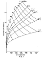
- Figure 1 is a chart showing the predicted instanteous recovery efficiency of various recovery gauzes in a nitric acid plant, having a nitrogen loading of 13.6 tonnes (15 tons) of nitrogen in ammonia per square meter of catalyst gauze per day, operating at a catalyst temperature of 900°C and an ammonia concentration in the feed of 10 m/o (mole percent).
- Figures 2 and 3 are charts which are analogous to Figure 1, except that the corresponding nitrogen loadings are 51.7 and 90.7 tonnes (57 and 100 tons) respectively.
- Figure 4 is a plot of the recovery function "φ" as a function of wire diameter for a variety of mesh numbers for a linen weave gauze.
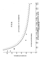
- Figure 5 is a chart showing anticipated platinum loss as a function of nitrogen loading for a typical nitric acid plant.
- Figure 6 is a graph showing the average recovery efficiencies obtainable with the present invention over the catalyst cycle as a function of nitrogen loading for a typical plant.
- Figure 7 is a comparison of predicted recovery efficiencies with a number of experimentally determined points.
- Figure 8 is an isometric view of a typical linen weave gauze.
- Figure 9 is a cross-sectional view of the catalyst and recovery gauze package in a nitric acid reactor.
- Figure 10 is a schematic of the nitric acid reactor.
- In many cases, high efficiencies can be obtained by using a gauze configuration in which the initial product of the mesh (in wires per unit length) and wire diameter exceeds 02 for gauzes containing a major proportion of palladium and a minor proportion of nickel. Preferably, the initial product of the mesh and the wire diameter will be in the range of from 02 to 0.9. For the lower swelling alloys, such as palldium-gold, the initial product of the mesh and wire diameter should be at least 3.0 and preferably in the range of from 0.3 to 0.9, more preferably from 0.35 to 0.9. For 95% Pd:5% Ni gauzes, it is preferred that the mesh N be in the range of from 3.9 to 31.5 cm-' (10 to 80 in-'), dw is in the range of from 0.0076 to 0.229 cm (0.003 to 0.090 inches), and their respective values are such that the initial product of N and dw is greater than 02.
- In practice, for purposes of the present invention under the conditions encountered in most commercial plants, the initial instantaneous recovery efficiencies (71), that is the percentage of platinum in the stream that is recovered by a single gauze having high palladium content, may be estimated by the use of the quasi- empirical formula


- For a square linen weave gauze, such as those most often encountered in practice, the following approximations are useful;


- Methods of determining the appropriate mass transfer correlation coefficient "C" and mass transfer correlation exponent "m" are well-known to those skilled in the art. A notable summary of the literature pertaining to the usual configurations is found in "Estimation of Platinum Catalyst Requirement for Ammonia Oxidation" by Roberts and Gillespie in Advances in Chemistry Series, Number 133, Chemical Reaction Engineering II, 1974 pp. 600-611. For more unusual configurations, these constants may be determined experimentally. For the common stacked screen gauzes, suitable correlations may be found in Satterfield and Cortez, Ind. Eng. Chem. Fundamentals (1970) 9, 613 and Shah, Ph.D. Thesis, University of Bir- mingham, England (1970). For the purposes of this invention,
equation 1 will work adequately with values for "C" of .94 and for "m" of .7 for the screens, reactors and flow conditions described in this application, if the values of Schmidt number and viscosity given below are used, even though the diffusing species may not necessarily be platinum oxide. - To expedite design of the recovery gauze for a particular plant, efficiency vs. wire diameter graphs similar to Figures 1, 2 and 3 can be constructed using
formula 1. - As a practical matter, the properties of the gas streams vary only by small amounts over the temperature ranges encountered in practice of from about 810° to about 9600, so that properties at 900°C can be used with only slight error. Similarly, the concentration of the feed to the catalyst is .normally regulated to between 10.0 to 10.5 m/o (mole percent) ammonia and 90.0 to 89.5 m /o air, so the composition of the reaction products from the catalyst gauze remains constant, so that physical properties in that range can be used: In these ranges, the Schmidt No. is about .9 - .95 for diffusion of platinum oxide vapours in air and the dynamic viscosity of the gas is about 4.2 x 10⁻⁶ Pa.s (about 4.2 x 10⁻⁵ poise).
- Accordingly, the efficiency is determined primarily by the mesh "N", and wire diameter "dw", for a given nitrogen loading "Lm", where the nitrogen loading "Lm" is the number of tonnes of nitrogen (in ammonia) passed through each square meter of the catalyst gauze per day (or "L", where the nitrogen loading "L" is the number of short tons of nitrogen (in ammonia) passed through each square meter of the catalyst gauze per day). Thus efficiency can be plotted as a function of wire diameter for a variety of mesh sizes. Further, void fraction can be shown parametrically on the same graph, so that efficiency and the void fraction can be determined simultaneously for each given combination of wire diameter and mesh. For a given void fraction and number of gauze sheets, the pressure drop through the gauze can be estimated using known correlations. To obtain high recovery efficiency without excessive pressure drop across the gauze, it is preferred that the volumetric void fraction (71) be between about 0.76 and about 0.5. Volumetric void fractions from about 0.5 down to about 0.3 can provide even better recovery efficiencies, but care must be exercised to properly support the recovery gauze so that it is not damaged or displaced by the force of the stream of gas passing through it. In many applications, volumetric void fractions between about 0.685 and about 0.5 will provide an excellent combination of especially high recovery efficiency with acceptable pressure drop. Void fractions of about 0.3 and lower can be used to provide extremely high recovery efficiencies, but many existing plants would require modification of the gauze support to withstand and properly distribute the resulting force of the stream on the gauze. In some circumstances, the cost of power due to pressure drop may also be of some significance. However, in practice, it is normally sufficient to limit consideration to volumetric void fractions above about 0.3 and preferably in the range of from about 0.5 to about 0.76. The most preferred range of void fractions is from about 0.5 to about 0.685.
- The method of fabricating gauzes according to the present invention is easily accomplished by plotting at least a portion of the appropriate efficiency vs. wire diameter graph for the conditions, such as temperature, pressure and nitrogen loading of the plant under consideration. Then the catalyst cycle length line can be plotted on this graph using the following procedure, such that if a mesh and wire diameter combination near the catalyst cycle length line is chosen, the average recovery efficiency of the gauze over the catalyst cycle (n ) will be within the range of this invention.
- The catalyst cycle length line is plotted by determining which gauzes will yield acceptable efficiencies (η) by drawing a horizontal line corresponding to the minimum acceptable efficiency across the appropriate efficiency vs. wire diameter graph, such as Figures 1-3. Then the appropriate recovery gauze cycle lengths "T" for a variety of mesh sizes and wire diameters above this horizontal line are determined using the formula


- Provided that the recovery gauze cycle length of preceding gauzes has not been exceeded, the recovery gauze cycle length of the nth gauze is determined by using the formula

- If it is desired to design recovery packs so that there are approximately equal recovery gauze cycle lengths obtained for each sheet in the pack, the first sheet of the pack should be designed as described previously, so that it will have an average recovery efficiency over the catalyst cycle within an acceptable range, and preferably greater than 1 -exp (-3.22/Lme1), i e. greater than 1 -exp (-3.45/Lo'). The recovery gauze cycle length for this first gauze sheet will be in the range of from about nine-tenths to eleven-tenths of the planned catalyst gauze cycle length for the plant. The geometric configuration of each succeeding gauze sheet may then be chosen, so that the following relationship is approximately satisfied for each gauze sheet:

η - Using the method of the present invention for a given plant, it is possible to obtain average single sheet recovery efficiencies over the catalyst cycle (
η ) which are greater than the values given incolumn 2 of Table I. Using preferred configurations, it is possible to obtain average efficiencies greater than those given in column 3. Figure 6 is a graph illustrating the average recovery efficiencies obtainable over the catalyst cycle length with the preferred gauzes of the present invention as a function of nitrogen loading, as compared to efficiencies reported in the prior art. - In practice, recovery gauzes almost always contain a major proportion of palladium or gold and minor additions of other alloying elements which improve mechanical properties. By major proportion of palladium, it is meant that the recovery gauze contains at least about 70% palladium by weight. Preferably, the recovery gauzes will contain at least about 80% palladium and more preferably 90%. The most preferred recovery gauzes contain at least about 95% palladium by weight. Perhaps the most widely used alloy has been an alloy containing 80% palladium and 20% gold. While this alloy has found wide use, alternatives have been sought, since inclusion of gold greatly increases the cost of the gauze. Other alloying elements for palladium include other platinum group metals, nickel, manganese, chromium, carbon, boron, and the like. Particularly useful palladium alloys include palladium/gold, palladium/platinum, palladium/nickel, palladium/copper, palladium/ruthenium, and palladium/silver. Alternatively, gauzes containing a major proportion of gold and a minor proportion of a platinum group metal have been suggested, since it has been reported that gold does not volatilize to the same extent as palladium. The ability of these gold-rich alloys to withdraw platinum seems to be somewhat less than the ability of palladium-rich alloys. In the same fashion as the palladium-rich alloys, the mechanical properties of the gold-rich alloys may be improved by adding metals which have a greater affinity for platinum than for oxygen, such as tantalum, niobium, and the like. Other suitable alloying elements include titanium, zirconium, chromium, nickel, manganese, and the like.

- For the purposes of the present invention, the preferred alloys are palladium/gold and palladium/nickel alloys, particularly alloys containing at least about 80% palladium. 95% palladium and 5% nickel is a particularly advantageous alloy for the practice of the present invention, since it is relatively inexpensive, is easily fabricated and upon exposure to the hot platinum-containing effluent, the wires swell and may double in diameter before they are to be removed. In some cases, the diameter of the wires in the gauze may more than double, reaching approximately 2.5 times their initial diameter. When properly allowed for, this swelling can be particularly advantageous, as the efficiency of the gauze increases as the wires swell. For example, in a plant having a nitrogen loading of 51.7 tonnes (57 tons) per square meter per day, a 14.2 cm-' (36 in-') mesh by 0.0173 cm (.0068 in) wire diameter gauze with an initial efficiency of about 11% could provide an efficiency of about 14% after the wires swell to 0.0305 cm (.012 in) and over about 18% if the wires reach 2.5 times their initial diameter. Thus, a gauze which provided an instantaneous efficiency which was initially outside the desired range, can swell to provide an average efficiency in the desired range, providing a much higher efficiency than would have been predicted based on its initial configuration.
- Thus, when nickel/palladium gauzes are used, a gauze may be selected such that its recovery efficiency based on its initial configuration is less than 1 - exp(-3.22/Lm•7), i.e. 1 - exp(-3.45/Le1), but upon swelling, these gauzes provide an average recovery efficiency over the catalyst cycle greater than 1 - exp(-3.22/Lm•7), i.e. greater than 1 - exp(3.45/Le1).
- In the case of 95% Pd:5% Ni, the average recovery efficiencies over the catalyst cycle (
η ) correlate best when recovery is predicted based upon the geometric mean of the initial and swelled diameters, but adequate correlation for the 80% Pd:20% Au gauzes can be obtained if recovery is predicted based upon initial diameter, since the effect of swelling -seems to be somewhat less pronounced. If it is desired to account for the effect of swelling in a palladium-gold alloy gauze, the geometric mean wire diameter may be estimated by multiplying the initial diameter by 1.1. Often for 95% Pd:5% Ni, the geometric mean diameter can be estimated satisfactorily by multiplying the initial diameter by a factor in the range of from about 1.4 to 1.6, depending on the location of the gauze in the recovery pack with the higher end of the range being used for the first or second layers in the pack and the lower end for the fifth and sixth layers. See Operating Example 11 for more details. Thus,Equation 1 can also be used to estimate average efficiences if geometric mean wire diameters are used and the recovery gauze cycle length is not exceeded. - As illustrated in Figure 8, the recovery gauzes used in the method of the present invention may be employed in the form of
screens 10 havingwires 20 andopenings 30. As explained, the combination of the diameter ofwires 20 in centimeters and the mesh or number of wires per lineal centimeter determining the mass transfer parameters (MTP) of the screen according to the formula -


- As shown in Figure 9, prior to a typical run, a
gauze ensemble 20 is placed into reaction chamber 40 (Figure 10) of acombustion vessel 42. Thisensemble 20 includesrecovery gauze pack 21 andcatalyst pack 25 placed adjacent to one another.Catalyst pack 25 containsindividual sheets 24 of catalyst in the form of nettings. or screens stacked one atop the other. In Figure 9, the catalyst pack is depicted with seven sheets of catalyst, but it is to be understood that the precise number of sheets is not critical and they may be increased or decreased as needed to effect an essentially complete conversion of ammonia to nitrogen oxides. One such catalyst consists of 90% platinum/5% rhodium/5% palladium, but other platinum-containing catalysts may also be employed with good results.Recovery gauze pack 21 contains two sheets ofrecovery gauze 22 sandwiched between separator screens 23. The recovery gauze packs must be of sufficient mechanical strength to withstand the force of the process stream at high reaction temperatures while simultaneously enduring the corrosive effects of the residual ammonia, oxygen and nitrogen oxide products which are formed during the process. - A recovery gauze is to be designed for a nitric acid plant operating at 900°C, 10% NH3 and a loading of 13.6 tonnes (15 U.S. tons) of nitrogen in ammonia per square meter per day. The plant operates on a cycle length of 130 days, at a pressure of 690 kPa gauge (100 p.s.i.g.). To begin, a diagram (Figure 1) is prepared of the single sheet efficiency of a recovery gauze as a function of mesh size and wire diameter. Figure 6 is then consulted, and it is determined that an efficiency in excess of 40% should be obtainable. It can be seen from Figure 1 that a 19.7 cm-' (50 in-') mesh gauze with wires 0.024 cm (.0095 in) in diameter would provide a suitable instantaneous efficiency (71). Therefore, to allow for swelling, a 19.7 cm-' (50 in-') mesh gauze with wires 0.0152 cm (.006 in) diameter is prepared from 95% Pd:5% Ni. Upon use in the reactor, the gauze swells by a factor of about 2.5 to a wire diameter of about 0.038 cm (.015 in), providing an efficiency (based on the geometric average wire diameter of 0.024 cm (.0095 in)) in excess of 40%. From Figure 5, it can be estimated that such a plant can be expected to lose about .88 to .99 grams of platinum for each tonne (0.8 to 0.8 g per ton) of nitrogen converted. Thus, about 12.75 grams of platinum per day are presented to each square meter of gauze which weighs about 916 g/m2. Upon operation, the first gauze sheet can be expected to remove over 40% of this for a recovery of about 5.1 grams of Pt per day per square meter of gauze, or about 665 g/m2 over the catalyst cycle. The recovery gauze cycle length coincides closely with the planned cycle length of the plant, so this gauze may be used without a heavier, but less efficient gauze upstream of it. About .3 to .4 grams of palladium can be expected to be lost for each gram of Pt recovered. Three screens are used to achieve an average recovery efficiency of 78%. A successive finer and lighter screen may be used downstream to recover a portion of the residual platinum, if so desired.
- A gauze is to be designed for a plant similar to that in Example 1, except that the loading is 51.7 tonnes (57 tons)/m2-day, and the cycle length is 60 days. According to Figure 5, a plant of this type can be expected to lose between about 1.54 and 1.76 grams of Pt per tonne (1.4 to 1.6 g per ton) of ammonia converted. Figure 6 shows that an efficiency of more than 17% can be obtained. It can be seen from Figure 2 that this can be obtained with a 23.6 cm-' (60 in-') mesh screen having a wire diameter of 0.0152 cm (.006 in). An 80% Pd:20% Au screen having these dimensions is selected. Upon operation, about 85 grams of Pt are presented to each square meter of the screen and about 14.5 grams are collected each day. Six screens are used to provide an overall average recovery efficiency of 67%.
- A gauze is to be designed for a plant having a loading of 90.7 tonnes (100 tons) of nitrogen in ammonia per square meter per day, and a cycle length of 60 days. According to Figure 5, a plant of this size can be expected to lose between about 1.87 and 2.09 grams of platinum for each tonne (1.7 to 1.9 g per ton) of nitrogen converted, while an efficiency in excess of 12% can be obtained. However, if an 80% Pd:20% Au gauze having a mesh of 31.5 cm-' (80 in-') and a wire diameter of 0.0127 cm (.005 in) is used, even though an efficiency of over 15% is obtained, the recovery gauze cycle length is shorter than the catalyst gauze cycle length. Therefore, coarser, heavier gauzes should be inserted upstream of the finer, lighter recovery gauzes after the catalyst gauze. Since a 31.5 cm-' (80 in-') mesh by 0.0127 mm (0.005 in) wire diameter gauze of 80% Pd:20% Au has a recovery gauze cycle length of 60 days with a platinum recovery of 948 glm2, the number of grams of Pt presented to each square meter of the first gauze must be decreased from about 180 grams to about 105. Thus, 4 coarse gauzes of 19.7 cm-' (50 in-') mesh by 0.0216 cm (.0085 in) wire diameter should be followed by 4 fine gauzes of 26.8 cm-' (68 in-1) mesh by 0.0152 cm (.006 in) wire diameter to achieve an overall recovery of 67%.
- A recovery gauze system is to be designed for a nitric acid plant operating at 4.5 bar (4.5 atmospheres) pressure and a nitrogen loading of 12.0 tonnes (13.2 tons) of nitrogen in ammonia per square meter per day over a catalyst gauze cycle length of 150 days. The catalyst loss rate is known to be 0.159 g of Pt and Rh per tonne (0.144 g per ton) of nitrogen. The production rate of the plant is 300 tonnes (330 tons) of HN03 per day, and the effective area of the reactor is 5.8 square meters.
- If two standard 31.5 cm-' (80 in-') mesh by 0.0079 cm (.0031 in) wire diameter recovery gauzes of 80% Pd:20% Au are used, the predicted recovery gauze cycle length is only about 130 days, resulting in an average recovery efficiency of the plant cycle length of approximately 46% per gauze or a total of 71 % for both gauzes.
- By following the procedure of Example I, it can be seen that if two 19.7 cm-' (50 in-1) mesh by 0.0163 cm (.0064 in) wire diameter recovery gauzes of 95% Pd:5% Ni are used instead of the standard gauzes, the predicted recovery gauze cycle length for the first gauze slightly exceeds 150 days for an average recovery efficiency over the cycle length of 72% per gauze for a total of 92%.
- Thus, each square meter of the improved gauzes of the present invention recover over 370 additional grams of platinum over each cycle length.
Claims (7)


Priority Applications (1)
| Application Number | Priority Date | Filing Date | Title |
|---|---|---|---|
| AT87201149T ATE63140T1 (en) | 1981-08-12 | 1982-08-06 | PROCESS FOR RECOVERING PLATINUM IN A NITRIC ACID PLANT. |
Applications Claiming Priority (6)
| Application Number | Priority Date | Filing Date | Title |
|---|---|---|---|
| US29211381A | 1981-08-12 | 1981-08-12 | |
| US29211481A | 1981-08-12 | 1981-08-12 | |
| US292113 | 1981-08-12 | ||
| US292114 | 1981-08-12 | ||
| US33133381A | 1981-12-16 | 1981-12-16 | |
| US331333 | 1981-12-16 |
Related Parent Applications (1)
| Application Number | Title | Priority Date | Filing Date |
|---|---|---|---|
| EP82304173.6 Division | 1982-08-06 |
Publications (3)
| Publication Number | Publication Date |
|---|---|
| EP0244921A2 true EP0244921A2 (en) | 1987-11-11 |
| EP0244921A3 EP0244921A3 (en) | 1988-04-27 |
| EP0244921B1 EP0244921B1 (en) | 1991-05-02 |
Family
ID=27404105
Family Applications (2)
| Application Number | Title | Priority Date | Filing Date |
|---|---|---|---|
| EP19870201149 Expired - Lifetime EP0244921B1 (en) | 1981-08-12 | 1982-08-06 | Method for recovering platinum in a nitric acid plant |
| EP19820304173 Expired - Lifetime EP0077121B2 (en) | 1981-08-12 | 1982-08-06 | Method for recovering platinum in a nitric acid plant |
Family Applications After (1)
| Application Number | Title | Priority Date | Filing Date |
|---|---|---|---|
| EP19820304173 Expired - Lifetime EP0077121B2 (en) | 1981-08-12 | 1982-08-06 | Method for recovering platinum in a nitric acid plant |
Country Status (13)
| Country | Link |
|---|---|
| EP (2) | EP0244921B1 (en) |
| JP (1) | JPH0615697B2 (en) |
| KR (2) | KR890002983B1 (en) |
| AT (2) | ATE63140T1 (en) |
| AU (3) | AU550041B2 (en) |
| BR (1) | BR8204717A (en) |
| DE (3) | DE3280330D1 (en) |
| DK (2) | DK171543B1 (en) |
| ES (4) | ES8404287A1 (en) |
| FI (4) | FI77789C (en) |
| IE (2) | IE58170B1 (en) |
| MX (1) | MX167846B (en) |
| NO (4) | NO167855C (en) |
Families Citing this family (11)
| Publication number | Priority date | Publication date | Assignee | Title |
|---|---|---|---|---|
| AU550041B2 (en) * | 1981-08-12 | 1986-02-27 | Engelhard Corporation | Recovering platinum and rhodium in nitric acid plant |
| FR2559787B1 (en) * | 1984-02-22 | 1992-09-18 | Louyot Comptoir Lyon Alemand | IMPROVED FABRIC FOR PLATINUM RECOVERY, ESPECIALLY IN NITRIC ACID SYNTHESIS PLANTS AND METHOD FOR MANUFACTURING AND USING THE SAME |
| EP0216493A1 (en) * | 1985-08-19 | 1987-04-01 | Engelhard Corporation | Platinum recovery using perforation resistant gauzes |
| US5268157A (en) * | 1991-03-16 | 1993-12-07 | Degussa Aktiengesellschaft | Process for the production of catalytic gas permeable nets and process for oxidizing ammonia |
| DE4206199C1 (en) * | 1991-03-16 | 1992-11-12 | Degussa Ag, 6000 Frankfurt, De | |
| GB9302531D0 (en) * | 1993-02-09 | 1993-03-24 | Johnson Matthey Plc | Improvements in pt recovery |
| RU2448177C1 (en) * | 2011-01-11 | 2012-04-20 | Открытое акционерное общество "Красноярский завод цветных металлов имени В.Н. Гулидова" (ОАО "Красцветмет") | Method of extracting rhenium from platinum and rhenium sulphide concentrate |
| RU2490349C1 (en) * | 2012-05-25 | 2013-08-20 | Открытое акционерное общество "Красноярский завод цветных металлов имени В.Н. Гулидова" (ОАО "Красцветмет") | Method of separating platinum and rhenium sulphides |
| RU2493276C1 (en) * | 2012-06-29 | 2013-09-20 | Леонид Асхатович Мазитов | Processing method of dead platinum-rhenium catalysts |
| RU2519209C1 (en) * | 2012-12-03 | 2014-06-10 | Открытое акционерное общество "Красноярский завод цветных металлов имени В.Н. Гулидова" (ОАО "Красцветмет") | Method of extracting rhenium from acidic solutions |
| EP4310210A1 (en) * | 2022-07-19 | 2024-01-24 | Yara International ASA | Volatile and precious metal recovery system made of stacked silver-comprising elements |
Citations (3)
| Publication number | Priority date | Publication date | Assignee | Title |
|---|---|---|---|---|
| GB1082105A (en) * | 1964-10-03 | 1967-09-06 | Degussa | A process for recovering the noble metal which is volatilised during catalytic reactions |
| DE1810554A1 (en) * | 1968-11-23 | 1970-06-04 | Degussa | Recovery of platinum |
| DE1483138B2 (en) * | 1965-08-19 | 1971-05-19 | Deutsche Gold und Silber Scheide anstalt vormals Roessler, 6000 Frankfurt | PROCESS FOR RECOVERY OF THE PRECIOUS METAL DEVOLVED IN CATALYTIC REACTIONS |
Family Cites Families (1)
| Publication number | Priority date | Publication date | Assignee | Title |
|---|---|---|---|---|
| AU550041B2 (en) * | 1981-08-12 | 1986-02-27 | Engelhard Corporation | Recovering platinum and rhodium in nitric acid plant |
-
1982
- 1982-07-29 AU AU86581/82A patent/AU550041B2/en not_active Expired
- 1982-08-06 DE DE8787201149T patent/DE3280330D1/en not_active Expired - Lifetime
- 1982-08-06 DE DE8282304173T patent/DE3279685D1/en not_active Expired
- 1982-08-06 EP EP19870201149 patent/EP0244921B1/en not_active Expired - Lifetime
- 1982-08-06 EP EP19820304173 patent/EP0077121B2/en not_active Expired - Lifetime
- 1982-08-06 AT AT87201149T patent/ATE63140T1/en not_active IP Right Cessation
- 1982-08-06 AT AT82304173T patent/ATE42971T1/en not_active IP Right Cessation
- 1982-08-06 DE DE198282304173T patent/DE77121T1/en active Pending
- 1982-08-09 DK DK357582A patent/DK171543B1/en not_active IP Right Cessation
- 1982-08-10 FI FI822784A patent/FI77789C/en not_active IP Right Cessation
- 1982-08-11 NO NO822734A patent/NO167855C/en not_active IP Right Cessation
- 1982-08-11 IE IE920904A patent/IE58170B1/en not_active IP Right Cessation
- 1982-08-11 IE IE193682A patent/IE58152B1/en not_active IP Right Cessation
- 1982-08-11 ES ES514916A patent/ES8404287A1/en not_active Expired
- 1982-08-11 BR BR8204717A patent/BR8204717A/en not_active IP Right Cessation
- 1982-08-11 JP JP13966382A patent/JPH0615697B2/en not_active Expired - Lifetime
- 1982-08-12 MX MX19399882A patent/MX167846B/en unknown
- 1982-08-12 KR KR8203610A patent/KR890002983B1/en active
-
1983
- 1983-04-14 ES ES521446A patent/ES521446A0/en active Granted
- 1983-04-14 ES ES521447A patent/ES521447A0/en active Granted
- 1983-04-14 ES ES521448A patent/ES521448A0/en active Granted
-
1985
- 1985-09-06 FI FI853420A patent/FI78123C/en not_active IP Right Cessation
- 1985-09-06 FI FI853419A patent/FI78122C/en not_active IP Right Cessation
- 1985-09-06 FI FI853418A patent/FI78121C/en not_active IP Right Cessation
- 1985-12-23 AU AU51599/85A patent/AU573941B2/en not_active Expired
- 1985-12-23 AU AU51600/85A patent/AU574548B2/en not_active Expired
-
1986
- 1986-10-10 NO NO864037A patent/NO167857C/en not_active IP Right Cessation
- 1986-10-10 NO NO864036A patent/NO167856C/en not_active IP Right Cessation
- 1986-10-10 NO NO864038A patent/NO167858C/en not_active IP Right Cessation
-
1989
- 1989-03-15 KR KR1019890003209A patent/KR890002984B1/en not_active IP Right Cessation
-
1991
- 1991-01-24 DK DK012191A patent/DK169182B1/en active
Patent Citations (3)
| Publication number | Priority date | Publication date | Assignee | Title |
|---|---|---|---|---|
| GB1082105A (en) * | 1964-10-03 | 1967-09-06 | Degussa | A process for recovering the noble metal which is volatilised during catalytic reactions |
| DE1483138B2 (en) * | 1965-08-19 | 1971-05-19 | Deutsche Gold und Silber Scheide anstalt vormals Roessler, 6000 Frankfurt | PROCESS FOR RECOVERY OF THE PRECIOUS METAL DEVOLVED IN CATALYTIC REACTIONS |
| DE1810554A1 (en) * | 1968-11-23 | 1970-06-04 | Degussa | Recovery of platinum |
Non-Patent Citations (2)
| Title |
|---|
| CHEMIE-ING.-TECHNIK, vol. 40, no. 24, 1968, pages 1229-1237, Weinheim, H. HOLZMANN "Platin-R}ckgewinnung bei der NH3-Verbrennung an Platin/Rhodium-Netzkatalysatoren" * |
| PLATINUM METALS REVIEW, vol. 13, no. 1, January 1969, pages 2-8, London, GB; H. HOLZMANN "Platinum recovery in ammonia oxidation plants" * |
Also Published As
Similar Documents
| Publication | Publication Date | Title |
|---|---|---|
| US4412859A (en) | Method for recovering platinum in a nitric acid plant | |
| EP0244921B1 (en) | Method for recovering platinum in a nitric acid plant | |
| EP0063450A1 (en) | Recovery of precious metal | |
| EP0087771A1 (en) | Improved methanation process and Raney catalyst therefor | |
| WO1992022674A1 (en) | Low pressure drop, high surface area platinum recovery system in a nitric acid plant | |
| US4497657A (en) | Method for recovering platinum in a nitric acid plant | |
| US4526614A (en) | Method for recovering platinum in a nitric acid plant | |
| US3057138A (en) | Apparatus for the separation of metals from fluids containing same | |
| US3873675A (en) | Catalyst and catalyst arrangement for the production of nitric acid | |
| US5160722A (en) | Low pressure drop, high surface area ammonia oxidation catalyst | |
| CA1185956A (en) | Foraminate element for the recovery of platinum metal and method of using same | |
| CA1185954A (en) | Foraminate element for the recovery of platinum metal and method of using same | |
| EP0216493A1 (en) | Platinum recovery using perforation resistant gauzes | |
| EP0519699B1 (en) | Low pressure drop, high surface area oxidation catalyst and catalyst for production of hydrocyanic acid | |
| JPH06256865A (en) | Catchment gauze for platinum recovery | |
| CN87108317A (en) | Be used to handle the material of ammonia | |
| EP0547071A1 (en) | Improvements in or relating to self-gettering catalysts | |
| EP0185510A2 (en) | Catchment packs | |
| PL107549B1 (en) | MESH OF STAINLESS METALS FOR RECOVERY OF PLATINATES, INCLUDING PLATINUM DURING AMMONIA OXIDATION | |
| HU180505B (en) | Laminar charge of noale metal catalyst for the oxydation of ammonia to nitrogen momoxide | |
| PL107548B1 (en) | MESH OF STAINLESS METAL FOR RECOVERY OF PLATINUM, INCLUDING PLATINUM IN THE PROCESS OF AMMONIA OXIDATION |
Legal Events
| Date | Code | Title | Description |
|---|---|---|---|
| PUAI | Public reference made under article 153(3) epc to a published international application that has entered the european phase |
Free format text: ORIGINAL CODE: 0009012 |
|
| AC | Divisional application: reference to earlier application |
Ref document number: 77121 Country of ref document: EP |
|
| AK | Designated contracting states |
Kind code of ref document: A2 Designated state(s): AT BE CH DE FR GB IT LI LU NL SE |
|
| PUAL | Search report despatched |
Free format text: ORIGINAL CODE: 0009013 |
|
| AK | Designated contracting states |
Kind code of ref document: A3 Designated state(s): AT BE CH DE FR GB IT LI LU NL SE |
|
| 17P | Request for examination filed |
Effective date: 19880920 |
|
| 17Q | First examination report despatched |
Effective date: 19900214 |
|
| GRAA | (expected) grant |
Free format text: ORIGINAL CODE: 0009210 |
|
| ITF | It: translation for a ep patent filed |
Owner name: SOCIETA' ITALIANA BREVETTI S.P.A. |
|
| AC | Divisional application: reference to earlier application |
Ref document number: 77121 Country of ref document: EP |
|
| AK | Designated contracting states |
Kind code of ref document: B1 Designated state(s): AT BE CH DE FR GB IT LI LU NL SE |
|
| REF | Corresponds to: |
Ref document number: 63140 Country of ref document: AT Date of ref document: 19910515 Kind code of ref document: T |
|
| REF | Corresponds to: |
Ref document number: 3280330 Country of ref document: DE Date of ref document: 19910606 |
|
| ET | Fr: translation filed | ||
| PLBE | No opposition filed within time limit |
Free format text: ORIGINAL CODE: 0009261 |
|
| STAA | Information on the status of an ep patent application or granted ep patent |
Free format text: STATUS: NO OPPOSITION FILED WITHIN TIME LIMIT |
|
| 26N | No opposition filed | ||
| PGFP | Annual fee paid to national office [announced via postgrant information from national office to epo] |
Ref country code: SE Payment date: 19920622 Year of fee payment: 11 |
|
| PGFP | Annual fee paid to national office [announced via postgrant information from national office to epo] |
Ref country code: LU Payment date: 19920707 Year of fee payment: 11 |
|
| PGFP | Annual fee paid to national office [announced via postgrant information from national office to epo] |
Ref country code: CH Payment date: 19920915 Year of fee payment: 11 |
|
| EPTA | Lu: last paid annual fee | ||
| PG25 | Lapsed in a contracting state [announced via postgrant information from national office to epo] |
Ref country code: LU Free format text: LAPSE BECAUSE OF NON-PAYMENT OF DUE FEES Effective date: 19930806 |
|
| PG25 | Lapsed in a contracting state [announced via postgrant information from national office to epo] |
Ref country code: SE Effective date: 19930807 |
|
| PG25 | Lapsed in a contracting state [announced via postgrant information from national office to epo] |
Ref country code: LI Effective date: 19930831 Ref country code: CH Effective date: 19930831 |
|
| REG | Reference to a national code |
Ref country code: CH Ref legal event code: PL |
|
| EUG | Se: european patent has lapsed |
Ref document number: 87201149.9 Effective date: 19940310 |
|
| PGFP | Annual fee paid to national office [announced via postgrant information from national office to epo] |
Ref country code: FR Payment date: 20010718 Year of fee payment: 20 |
|
| PGFP | Annual fee paid to national office [announced via postgrant information from national office to epo] |
Ref country code: DE Payment date: 20010719 Year of fee payment: 20 |
|
| PGFP | Annual fee paid to national office [announced via postgrant information from national office to epo] |
Ref country code: GB Payment date: 20010720 Year of fee payment: 20 Ref country code: AT Payment date: 20010720 Year of fee payment: 20 |
|
| PGFP | Annual fee paid to national office [announced via postgrant information from national office to epo] |
Ref country code: NL Payment date: 20010723 Year of fee payment: 20 |
|
| PGFP | Annual fee paid to national office [announced via postgrant information from national office to epo] |
Ref country code: BE Payment date: 20010810 Year of fee payment: 20 |
|
| BE20 | Be: patent expired |
Free format text: 20020806 *ENGELHARD CORP. |
|
| REG | Reference to a national code |
Ref country code: GB Ref legal event code: IF02 |
|
| PG25 | Lapsed in a contracting state [announced via postgrant information from national office to epo] |
Ref country code: GB Free format text: LAPSE BECAUSE OF EXPIRATION OF PROTECTION Effective date: 20020805 |
|
| PG25 | Lapsed in a contracting state [announced via postgrant information from national office to epo] |
Ref country code: NL Free format text: LAPSE BECAUSE OF EXPIRATION OF PROTECTION Effective date: 20020806 Ref country code: AT Free format text: LAPSE BECAUSE OF EXPIRATION OF PROTECTION Effective date: 20020806 |
|
| REG | Reference to a national code |
Ref country code: GB Ref legal event code: PE20 Effective date: 20020805 |
|
| NLV7 | Nl: ceased due to reaching the maximum lifetime of a patent |
Effective date: 20020806 |