EP0244575A2 - Pompe à engrenages internes - Google Patents
Pompe à engrenages internes Download PDFInfo
- Publication number
- EP0244575A2 EP0244575A2 EP87102429A EP87102429A EP0244575A2 EP 0244575 A2 EP0244575 A2 EP 0244575A2 EP 87102429 A EP87102429 A EP 87102429A EP 87102429 A EP87102429 A EP 87102429A EP 0244575 A2 EP0244575 A2 EP 0244575A2
- Authority
- EP
- European Patent Office
- Prior art keywords
- outlet
- outlet chamber
- housing
- teeth
- gear pump
- Prior art date
- Legal status (The legal status is an assumption and is not a legal conclusion. Google has not performed a legal analysis and makes no representation as to the accuracy of the status listed.)
- Granted
Links
Images
Classifications
-
- F—MECHANICAL ENGINEERING; LIGHTING; HEATING; WEAPONS; BLASTING
- F04—POSITIVE - DISPLACEMENT MACHINES FOR LIQUIDS; PUMPS FOR LIQUIDS OR ELASTIC FLUIDS
- F04C—ROTARY-PISTON, OR OSCILLATING-PISTON, POSITIVE-DISPLACEMENT MACHINES FOR LIQUIDS; ROTARY-PISTON, OR OSCILLATING-PISTON, POSITIVE-DISPLACEMENT PUMPS
- F04C15/00—Component parts, details or accessories of machines, pumps or pumping installations, not provided for in groups F04C2/00 - F04C14/00
- F04C15/06—Arrangements for admission or discharge of the working fluid, e.g. constructional features of the inlet or outlet
- F04C15/064—Arrangements for admission or discharge of the working fluid, e.g. constructional features of the inlet or outlet with inlet and outlet valves specially adapted for rotary or oscillating piston machines or pumps
- F04C15/066—Arrangements for admission or discharge of the working fluid, e.g. constructional features of the inlet or outlet with inlet and outlet valves specially adapted for rotary or oscillating piston machines or pumps of the non-return type
- F04C15/068—Arrangements for admission or discharge of the working fluid, e.g. constructional features of the inlet or outlet with inlet and outlet valves specially adapted for rotary or oscillating piston machines or pumps of the non-return type of the elastic type, e.g. reed valves
-
- F—MECHANICAL ENGINEERING; LIGHTING; HEATING; WEAPONS; BLASTING
- F04—POSITIVE - DISPLACEMENT MACHINES FOR LIQUIDS; PUMPS FOR LIQUIDS OR ELASTIC FLUIDS
- F04C—ROTARY-PISTON, OR OSCILLATING-PISTON, POSITIVE-DISPLACEMENT MACHINES FOR LIQUIDS; ROTARY-PISTON, OR OSCILLATING-PISTON, POSITIVE-DISPLACEMENT PUMPS
- F04C2/00—Rotary-piston machines or pumps
- F04C2/08—Rotary-piston machines or pumps of intermeshing-engagement type, i.e. with engagement of co-operating members similar to that of toothed gearing
- F04C2/082—Details specially related to intermeshing engagement type machines or pumps
- F04C2/084—Toothed wheels
Definitions
- the internal gear pump according to the preamble of claim 1 is known from DE-OS 34 44 859.
- Claim 2 indicates further training and function of the outlet chamber.
- the design according to claim 3 prevents tilting forces, in particular if the center line of the circular segment or in particular if the line which divides the circular segment into two equal radial halves lies on the cylindrical housing.
- the invention thus improves an internal gear pump which has so many rotating and mutually closed cells that there are always several - at least three - cells with a decreasing volume in the outlet zone.
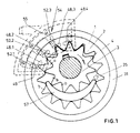
- the outer wheel 1 is freely rotatably mounted in the housing cylinder 31.
- the outer wheel 1 has an internal toothing 2.
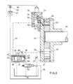
- the cylindrical housing 31 is closed on both sides by the covers 32 and 33.
- the shaft 34 is rotatably supported and driven by a motor vehicle engine, not shown.
- the inner wheel 3 is rotatably mounted on the shaft 34.
- the inner wheel 3 has an outer toothing 4, which is in engagement with the internal toothing 2 of the outer wheel 1.
- the interior of the pump which is outside the engagement area, can be filled with sickle 57.
- the sickle hugs the circles of the gears to a large extent.
- the inlet channel 35 is located in the cover 33.
- the inlet channel 35 is connected to the sump 36 via a throttle 37.
- a pressure control valve 39 is located in a bypass 38, which is connected parallel to the throttle duct 37.
- the piston 40 of the pressure control valve controls the opening of the bypass duct 38 to the sump 36 with its control edge 41.
- the piston is on one side with a spring 42 charged. On the opposite side, the piston in control chamber 43 is acted upon by the outlet pressure via control line 44.
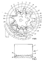
- the pump forms on the outlet side between the meshing teeth of the outer wheel 1 and the inner wheel 3 four (Fig. 1) or three (Fig. 4) in the circumferential and axial direction closed cells which have been completely or partially filled with oil via inlet channel 35.
- each outlet kidney 49 opens on the outside of the cover 33 as close as possible to and axially above the housing 31.
- the outlet channels do not necessarily have to be drilled through the cover with a radial component. It is also possible, for example, for the outlet channels to be radial grooves in the side of the gearwheels facing Cover 33 are executed and then open into the outlet bores 52 of the outlet chamber 51 through an axial branch channel in the lid.
- An outlet housing 50 is placed pressure-tight on the cover 33.
- the outlet housing 50 forms an outlet chamber which is connected to the outlet kidneys 48.1 to 48.4 via a pressure channel 49 and a bore 52.
- the bores 52.1, 52.2 and 52.3 are each closed by a check valve.
- the check valve is formed by an m-shaped plate which is screwed against the wall 53 of the outlet housing 50.
- the tongues protruding from the common crossbeam 55 of the check valve 54 cover the bores 52. Therefore, these tongues act as check valves.
- Each check valve only releases the connection from the respective pressure cell formed between the teeth via the respective outlet kidney 48, pressure channel 49 and bore 52 if the pressure of the outlet cell is at least equal to the outlet pressure in the outlet chamber 51.
- the last and smallest pressure cell is connected directly to the outlet chamber via kidney 48.4 and corresponding channels 49, 52.
- outlet openings 48.1, 48.3, 48.5 are introduced in the cover 33.
- Two outlet openings 48.2, 48.4 are introduced into the cover 32.
- the outlet openings of the cover 33 are arranged offset with respect to the outlet openings of the cover 32. That means: in the projection onto a normal plane, the outlet openings in the cover 33 or 32 do not overlap - as shown in FIG. 4.
- the outlet openings nestle closely with their radially inner edge 27 (inner edge) to the line of engagement 11, in such a way that between the line of engagement 11 and the inner edge 27 only a narrow, but sufficiently sealing for the seal Sealing web 28 remains.
- the width of the outlet openings 48.1 to 48.5 is selected so that the outlet openings are covered by the cross section of the teeth 2 of the ring gear 1 with the teeth in a corresponding position, sufficient sealing surfaces also remaining in the circumferential direction.
- the outlet openings extend into the area of the outer circumference of the ring gear and in any case up to the outermost area with which the bottom of the tooth gaps of the ring gear 1 opens on the end face of the covers 32, 33.
- tooth space base 30 represents half the shell of a circular cylinder, the axis of which lies on the plane of symmetry of the tooth space and essentially on the pitch circle or slightly radially outside of the pitch circle 7 of the ring gear.
- the bottom of the tooth space is again provided with a funnel-shaped extension 26 at both ends.
- the funnel-shaped extension 26 extends radially to almost the outer circumference of the ring gear.
- the funnel-shaped extension 26 can also extend in the circumferential direction. However, it is in any case radially outside of the pitch circle 7 of the ring gear 1. If the oil outlet is only provided on one side in a pump according to the invention, the funnel-shaped extension is also only on the relevant side.
- outlet openings 48.1 to 48.5 now extend radially outwards at least so far that they also cover the funnel-shaped extensions 26 on the end faces of the outer wheel 1.
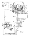
- each cover 32, 33 contains five outlet openings, only one of these outlet openings can be seen in each cover 32, 33.
- These outlet openings are designated there by 48.
- Each of the outlet openings is connected to an outlet channel 49 drilled in the cover 32, 33.
- the outlet channel is also directed radially outwards, as shown in FIG. 2. Therefore, each outer channel 49 opens on the outside of the cover 32 and 33 as close as possible to the housing 31.
- the outlet channels do not necessarily have to be drilled through the cover with a radial component. It is e.g. it is also possible that the outlet channels are designed as radial grooves in the side of the cover 32 or 33 facing the gearwheels and then open into the outlet bores 52 of the outlet chamber 51 through an axial branch channel in the respective cover.
- An outlet housing 50 is placed pressure-tight on each cover 32, 33.
- Each outlet housing 50 forms an outlet chamber which is connected on one side to the outlet openings 48.1, 48.3, 48.5 and on the other side to the outlet openings 48.2, 48.4 each via a pressure channel 49 and a bore 52.
- the bores 52 (cf. FIG. 4) are each closed by a check valve, with the exception of that bore which is connected to the outlet opening 48.5.
- the outlet opening 48.5 is located at the end of the pressure zone immediately before the pitch point. Both outlet chambers are connected to the common pressure channel 56.
- the check valves on both sides are formed by an n-shaped plate, which is screwed against the wall 53 of the outlet housing 50.
- the tongues protruding from the common crossbeam 55 of the check valve 54 cover the bores 52. Therefore, these tongues act as check valves.
- Each check valve only releases the connection from the respective pressure cell formed between the teeth via one of the outlet openings 48, pressure channels 49 and bores 52 if the pressure of the outlet cell is at least equal to the outlet pressure in the outlet chamber 51.
- the last and smallest pressure cell is directly connected to the outlet chamber via opening 48.5 and corresponding channels 49, 52.
- both flanks of each tooth are formed according to a special toothing law.
- This interlocking law ensures that there is a high degree of coverage that is greater than 2, preferably greater than 3. This has the effect that the teeth are in engagement with one another in approximately the entire rotational range between the intersection of the two tip circles 5 and 9 and the pitch point and, as a result, more than two tooth cells are formed by two successive tooth pairs in each case. These tooth cells are mutually closed in the circumferential direction.
- This gearing law includes that the driving flanks of the inner wheel 3 and outer wheel 1 also have a correspondingly large degree of coverage. It is now provided that the degree of coverage is less on the driving side of the teeth than on the sealing side of the teeth.
- the tooth flanks which lie sealingly on top of each other in the pressure zone between the intersection of the tip circles and the pitch point and form the tooth cells that are sealed off from one another, are produced according to the toothing law described above. These flanks are referred to as sealing flanks in the context of this application.
- flanks of the teeth of ring gear 1 and pinion 3, which serve to transmit the torque between inner wheel 3 and ring gear 1 (driving flanks), are produced with a lower degree of coverage, which is preferably between 1 and 2. This is done in that only a partial area of the driving flanks of the outer wheel 1 and / or the inner wheel 3 is produced according to the toothing law (engagement area of the flank).
- the engagement area 64 of the drive flanks of the ring gear extends radially a little way inward from the pitch circle 7 of the ring gear.
- the cross-sectional area by which the driving flank of the ring gear deviates from the profile produced by toothing is designated by 65.
- the engagement area 66 of the drive flanks of the inner wheel 1 extends radially a little outward from the pitch circle 8.
- the cross-sectional area of the tooth head by which the driving tooth flanks of the inner wheel 3 recede relative to the ideal tooth profile is designated by 67.
- either the driving flanks of the ring gear or the driving flanks of the pinion or both can be provided with such cutouts 65 and 67, respectively.
- the latter solution has the advantage that only low flow velocities arise on the suction side of the pump.
- the engagement area 64 of the driving flanks of the ring gear and / or the inner wheel which is formed according to the gearing law, is dimensioned such that on the one hand at least one pair of teeth of the ring gear and the inner wheel are always in engagement with one another, but on the other hand fewer tooth pairs are engaged on the driving side than on the Sealing side.
- the degree of coverage on the engagement side is preferably not greater than 2 due to the correspondingly short design of the engagement areas.
- Each outlet chamber 51 has an outlet which leads into the common lubricating oil channel 56.
- Each outlet chamber circumscribes in the normal section - as can be seen from FIG. 1 - essentially an annular segment. This ring segment lies essentially on and axially above the cylindrical housing shell 31.
- the outlet housing is therefore not supported on the deformable part of the cover 33 but on the cylindrical housing shell 31.
- the center line the radius of which is the arithmetic mean of the inner radius and the outer radius, preferably lies above the housing jacket. It is even more favorable that the partial areas of the ring segment, which lie on both sides of the housing shell 31, are essentially of the same area.
- the embodiment of Figures 3 to 5 also has the advantage that the outlet chambers 51 sit on both sides of the pump housing or the shell 31. Therefore, the compressive forces exerted on the pump housing from the outlet chambers 51 cancel each other out.
- the pump housing is only loaded symmetrically. Therefore, one-sided deformation and warping of the housing cannot occur. This makes it easier to comply with the necessary tolerances.
- the lubricating oil pump also meets other requirements of special operating conditions. For example, occur that the lubricating oil heats up excessively or that engine parts have to be cooled by lubricating oil due to special performance requirements.
- a further short-circuit channel 58 is provided between the inlet 35 of the pump and the oil sump 36.
- An electromagnetically switched valve 59 is located in this short-circuit channel. This valve is actuated via signal line 60 and amplifier 61 by a temperature sensor 62.
- the temperature sensor can be used, for example, to measure the oil temperature or the temperature of a machine part, for example a piston.
Landscapes
- Engineering & Computer Science (AREA)
- Mechanical Engineering (AREA)
- General Engineering & Computer Science (AREA)
- Rotary Pumps (AREA)
Applications Claiming Priority (4)
| Application Number | Priority Date | Filing Date | Title |
|---|---|---|---|
| DE3615212 | 1986-05-06 | ||
| DE3615212 | 1986-05-06 | ||
| DE3624517 | 1986-07-19 | ||
| DE19863624517 DE3624517A1 (de) | 1986-07-19 | 1986-07-19 | Innenzahnradpumpe |
Publications (3)
| Publication Number | Publication Date |
|---|---|
| EP0244575A2 true EP0244575A2 (fr) | 1987-11-11 |
| EP0244575A3 EP0244575A3 (en) | 1988-09-14 |
| EP0244575B1 EP0244575B1 (fr) | 1990-06-13 |
Family
ID=25843500
Family Applications (1)
| Application Number | Title | Priority Date | Filing Date |
|---|---|---|---|
| EP19870102429 Expired - Lifetime EP0244575B1 (fr) | 1986-05-06 | 1987-02-20 | Pompe à engrenages internes |
Country Status (2)
| Country | Link |
|---|---|
| EP (1) | EP0244575B1 (fr) |
| DE (1) | DE3763222D1 (fr) |
Cited By (2)
| Publication number | Priority date | Publication date | Assignee | Title |
|---|---|---|---|---|
| DE4129854A1 (de) * | 1991-09-07 | 1993-03-11 | Teves Gmbh Alfred | Zahnradpumpe mit einer nichtlinear von der drehzahl abhaengenden foerdermenge |
| GB2277963A (en) * | 1993-05-11 | 1994-11-16 | Barmag Luk Automobiltech | Hydraulic pump outlets |
Family Cites Families (4)
| Publication number | Priority date | Publication date | Assignee | Title |
|---|---|---|---|---|
| GB331054A (en) * | 1929-01-03 | 1930-07-03 | Thomas Winter Nichols | Improvements in rotary pumps, compressors and the like |
| US2107152A (en) * | 1936-08-13 | 1938-02-01 | Tuthill Pump Co | Reversible fuel pump |
| DE1403603A1 (de) * | 1961-08-08 | 1969-12-11 | Siemens Elektrogeraete Gmbh | Zellenverdichter |
| DE3005657C2 (de) * | 1980-02-15 | 1987-01-02 | Zahnradfabrik Friedrichshafen Ag, 7990 Friedrichshafen | Zahnradpumpe |
-
1987
- 1987-02-20 EP EP19870102429 patent/EP0244575B1/fr not_active Expired - Lifetime
- 1987-02-20 DE DE8787102429T patent/DE3763222D1/de not_active Expired - Fee Related
Cited By (2)
| Publication number | Priority date | Publication date | Assignee | Title |
|---|---|---|---|---|
| DE4129854A1 (de) * | 1991-09-07 | 1993-03-11 | Teves Gmbh Alfred | Zahnradpumpe mit einer nichtlinear von der drehzahl abhaengenden foerdermenge |
| GB2277963A (en) * | 1993-05-11 | 1994-11-16 | Barmag Luk Automobiltech | Hydraulic pump outlets |
Also Published As
| Publication number | Publication date |
|---|---|
| EP0244575B1 (fr) | 1990-06-13 |
| EP0244575A3 (en) | 1988-09-14 |
| DE3763222D1 (de) | 1990-07-19 |
Similar Documents
| Publication | Publication Date | Title |
|---|---|---|
| EP0254077B1 (fr) | Pompe à engrenages internes | |
| DE3444859C2 (fr) | ||
| DE68902190T2 (de) | Innenzahnradpumpe. | |
| EP0712997A2 (fr) | ContrÔle des soupapes avec pompe à engrenages internes avec réglage de l'aspiration | |
| DE3319000C2 (fr) | ||
| DE4441915C2 (de) | Innenzahnradpumpe | |
| WO2009092719A2 (fr) | Pompe à engrenage intérieur, à volume variable | |
| DE3637229C2 (de) | Baueinheit aus einer Hydraulikpumpe und einer Vakuumpumpe | |
| DE60031459T2 (de) | Gerotormotor mit Schmiernuten | |
| DE69717211T2 (de) | Zugkraftverteiler für Kraftfahrzeuge | |
| DE1553004C3 (de) | Steuerdrehschiebereinrichtung an einer Rotationskolbenmaschine | |
| EP0244575B1 (fr) | Pompe à engrenages internes | |
| EP0315878B1 (fr) | Pompe à engrènement interne | |
| DE4107704C2 (de) | Hydraulikpumpe | |
| DE3737961A1 (de) | Innenzahnradpumpe | |
| EP0475109B1 (fr) | Pompe à engrenages internes pour fluide hydraulique | |
| DE69300335T2 (de) | Drehkolbenpumpe mit vereinfachtem Pumpengehäuse. | |
| EP0474001B1 (fr) | Pompe à engrenages internes pour fluide hydraulique | |
| DE3627414A1 (de) | Verbrennungsmotor | |
| EP0473025A1 (fr) | Pompe à engrenages internes pour fluide hydraulique | |
| EP0088811B1 (fr) | Pompe à palettes, spécialement pour directions assistées | |
| DE2142323A1 (de) | Flüssigkeitstrieb | |
| DE3022090A1 (de) | Druckmittelbetaetigter rotationskolbenmotor | |
| DE3448253C2 (fr) | ||
| DE3448251C2 (fr) |
Legal Events
| Date | Code | Title | Description |
|---|---|---|---|
| PUAI | Public reference made under article 153(3) epc to a published international application that has entered the european phase |
Free format text: ORIGINAL CODE: 0009012 |
|
| AK | Designated contracting states |
Kind code of ref document: A2 Designated state(s): DE FR GB IT |
|
| PUAL | Search report despatched |
Free format text: ORIGINAL CODE: 0009013 |
|
| AK | Designated contracting states |
Kind code of ref document: A3 Designated state(s): DE FR GB IT |
|
| 17P | Request for examination filed |
Effective date: 19880902 |
|
| 17Q | First examination report despatched |
Effective date: 19890309 |
|
| ITF | It: translation for a ep patent filed | ||
| GRAA | (expected) grant |
Free format text: ORIGINAL CODE: 0009210 |
|
| AK | Designated contracting states |
Kind code of ref document: B1 Designated state(s): DE FR GB IT |
|
| ET | Fr: translation filed | ||
| REF | Corresponds to: |
Ref document number: 3763222 Country of ref document: DE Date of ref document: 19900719 |
|
| GBT | Gb: translation of ep patent filed (gb section 77(6)(a)/1977) | ||
| ITTA | It: last paid annual fee | ||
| PLBE | No opposition filed within time limit |
Free format text: ORIGINAL CODE: 0009261 |
|
| STAA | Information on the status of an ep patent application or granted ep patent |
Free format text: STATUS: NO OPPOSITION FILED WITHIN TIME LIMIT |
|
| 26N | No opposition filed | ||
| PGFP | Annual fee paid to national office [announced via postgrant information from national office to epo] |
Ref country code: FR Payment date: 19990111 Year of fee payment: 13 |
|
| PGFP | Annual fee paid to national office [announced via postgrant information from national office to epo] |
Ref country code: GB Payment date: 19990119 Year of fee payment: 13 |
|
| PGFP | Annual fee paid to national office [announced via postgrant information from national office to epo] |
Ref country code: DE Payment date: 19990204 Year of fee payment: 13 |
|
| PG25 | Lapsed in a contracting state [announced via postgrant information from national office to epo] |
Ref country code: GB Free format text: LAPSE BECAUSE OF NON-PAYMENT OF DUE FEES Effective date: 20000220 |
|
| GBPC | Gb: european patent ceased through non-payment of renewal fee |
Effective date: 20000220 |
|
| PG25 | Lapsed in a contracting state [announced via postgrant information from national office to epo] |
Ref country code: FR Free format text: LAPSE BECAUSE OF NON-PAYMENT OF DUE FEES Effective date: 20001031 |
|
| PG25 | Lapsed in a contracting state [announced via postgrant information from national office to epo] |
Ref country code: DE Free format text: LAPSE BECAUSE OF NON-PAYMENT OF DUE FEES Effective date: 20001201 |
|
| REG | Reference to a national code |
Ref country code: FR Ref legal event code: ST |
|
| PG25 | Lapsed in a contracting state [announced via postgrant information from national office to epo] |
Ref country code: IT Free format text: LAPSE BECAUSE OF NON-PAYMENT OF DUE FEES;WARNING: LAPSES OF ITALIAN PATENTS WITH EFFECTIVE DATE BEFORE 2007 MAY HAVE OCCURRED AT ANY TIME BEFORE 2007. THE CORRECT EFFECTIVE DATE MAY BE DIFFERENT FROM THE ONE RECORDED. Effective date: 20050220 |