EP0244491A1 - Medizinisches Instrument zur Knochenentfernung - Google Patents
Medizinisches Instrument zur Knochenentfernung Download PDFInfo
- Publication number
- EP0244491A1 EP0244491A1 EP86105889A EP86105889A EP0244491A1 EP 0244491 A1 EP0244491 A1 EP 0244491A1 EP 86105889 A EP86105889 A EP 86105889A EP 86105889 A EP86105889 A EP 86105889A EP 0244491 A1 EP0244491 A1 EP 0244491A1
- Authority
- EP
- European Patent Office
- Prior art keywords
- barrel
- shaft
- bone
- medical instrument
- handle
- Prior art date
- Legal status (The legal status is an assumption and is not a legal conclusion. Google has not performed a legal analysis and makes no representation as to the accuracy of the status listed.)
- Granted
Links
- 210000000988 bone and bone Anatomy 0.000 title claims abstract description 31
- 238000005520 cutting process Methods 0.000 claims abstract description 28
- 230000007246 mechanism Effects 0.000 claims abstract description 16
- 238000007789 sealing Methods 0.000 claims description 4
- 241000283984 Rodentia Species 0.000 abstract description 5
- 210000003414 extremity Anatomy 0.000 description 5
- 208000028389 Nerve injury Diseases 0.000 description 1
- 229910000639 Spring steel Inorganic materials 0.000 description 1
- 208000027418 Wounds and injury Diseases 0.000 description 1
- 230000005540 biological transmission Effects 0.000 description 1
- 238000004140 cleaning Methods 0.000 description 1
- 230000009850 completed effect Effects 0.000 description 1
- 238000011109 contamination Methods 0.000 description 1
- 239000012634 fragment Substances 0.000 description 1
- 210000003141 lower extremity Anatomy 0.000 description 1
- 238000000034 method Methods 0.000 description 1
- 238000012986 modification Methods 0.000 description 1
- 230000004048 modification Effects 0.000 description 1
- 230000008764 nerve damage Effects 0.000 description 1
- 230000000717 retained effect Effects 0.000 description 1
- 210000000278 spinal cord Anatomy 0.000 description 1
Images

Classifications
-
- A—HUMAN NECESSITIES
- A61—MEDICAL OR VETERINARY SCIENCE; HYGIENE
- A61B—DIAGNOSIS; SURGERY; IDENTIFICATION
- A61B17/00—Surgical instruments, devices or methods
- A61B17/16—Instruments for performing osteoclasis; Drills or chisels for bones; Trepans
- A61B17/1604—Chisels; Rongeurs; Punches; Stamps
- A61B17/1606—Chisels; Rongeurs; Punches; Stamps of forceps type, i.e. having two jaw elements moving relative to each other
- A61B17/1608—Chisels; Rongeurs; Punches; Stamps of forceps type, i.e. having two jaw elements moving relative to each other the two jaw elements being linked to two elongated shaft elements moving longitudinally relative to each other
- A61B17/1611—Chisels; Rongeurs; Punches; Stamps of forceps type, i.e. having two jaw elements moving relative to each other the two jaw elements being linked to two elongated shaft elements moving longitudinally relative to each other the two jaw elements being integral with respective elongate shaft elements
Definitions
- This invention relates generally to forceps of the rongeur or bone cutting type. It has long been an object in the art to provide simple, inexpensive forceps capable of easy disassembly and cleaning, and most importantly capable of safe and efficient operation.
- Prior patents issued in this art have proposed possible solutions. Typical of the prior art is the patent issued to De Vilbiss, U. S. Patent No. 1,040,523, which provides a lever mechanism comprising a handle having two sides arranged to pivot towards one another about a central axis. On extensions of these handle members there is provided a jaw mechanism comprising a first movable jaw arranged to travel within a slot defined within a second movable jaw. Bone seized between the jaws is pulled within the slot as it is cut.
- a problem associated with this and other mechanisms in the art is that uncontrolled force is applied to the bone surface surrounding the cutting area, such that possible bone breakage and splintering may occur. If operating near the spinal cord, possible nerve damage may result. Further, bone chips cut from the bone structure are not well contained by the instrument and contamination of the wound may result. Finally, with the pivot placed between the jaw mechanism and the lever handles limited mechanical advantage is available, making the instrument tiring to use.
- an improved forcep or rongeur having a jaw mechanism comprised of a barrel member having a honed cutting edge on one extremity thereof and having a shaft member located within and arranged for reciprocal motion. On the shaft member there is provided a plate member attached at one extremity to trap bone against the cutting edge.
- a lever mechanism is provided having paired handle levers joined by a pivot and having the barrel and shaft members attached to the handle levers between the handle portion and the pivot.
- a cavity arranged to slide within the barrel progressively as the cutting operation proceeds, gradually drawing severed bone within the capturing cavity, allowing for a cutting action rather than a crushing action, thereby relieving pressure on the plate member and thus reducing the possibility of breaking said member while cutting bone structures.
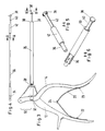
- FIG. 1 there is shown the forceps of the preferred embodiment of the present invention. Specifically there is shown a paired handle member 12 and 14 arranged to be held within the human hand and pulled together in the direction of the arrow 16 much in the same manner as a pair of pliers. This handle pair is arranged to pivot about the axis 18 and each is arranged as shown in the drawing to support and actuate the barrel and shaft cutting mechanism as more fully described below.
- a squeezing force on the paired handle members closes the handles in the direction of the arrow 16, and concurrently compresses the intermediate spring 20 located between the handle pair. This generates a returning force to return the handles to their starting position as shown in Figure 3.
- the return spring is typically of spring steel made of distinct and separate members, each rigidly attached to respective individual handle members at the lower extremity 22 and 23 respectively, while being hingedly interlocked at the intermediate contacting point 24.
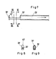
- a barrel member 26 comprised of a cylinderical tube having external threads 28 at its point of attachment to the handle, and having at its other extremity a honed edge 30 (more clearly shown in Figure 6) for cutting bone pressed thereagainst.
- a honed edge 30 (more clearly shown in Figure 6) for cutting bone pressed thereagainst.
- the upper edge is honed for cutting with the lower edge 31 being angled away from the end to avoid contact with the reciprocating mechanisms.
- a shaft member pivotally attached at axis 32 to said second handle member and arranged to selectively protrude from said barrel at its other extremity.
- This shaft member ( Figure 4) is comprised of a first attachment portion 34 for connection to the pivot mount at the handle, and a force transmission portion 36 for transmitting the force of the handle leverage mechanism remotely to the site of the bone cutting at the distal end of the barrel.
- a bone cutting and trapping portion comprised of a contoured plate 38 mounted transversely to the distal end of the shaft. This plate is shown with increased thickness in the vicinity of its attachment to the shaft to resist breakage.
- a cavity portion 40 (see Figure 5) defined by a depression on such shaft.
- this cavity is formed by a flat depression represented by a cut away portion of said shaft.
- a sealing portion 42 is provided to close the gap between the barrel and the shaft as the shaft end is drawn into the barrel. This sealing portion acts to maintain the barrel free of debris and serves to eject bone fragment following a cutting sequence.
- FIG. 2 In operation (see Figure 2) there is shown a bone segment 52 with an unsevered portion 54 trapped between the shaft and plate 56 and the honed edge of the barrel 58. As the shaft is drawn towards the barrel, severed bone 60 is captured within the barrel. Once the stroke has been completed the forceps are removed from the cutting site, inverted, and the shaft extended from the barrel to fascilitate deposit of the severed bone into the proper receptacle.
- an improved forcep or rongeur having a jaw mechanism comprised of a barrel member having a honed cutting edge on one extremity thereof and having a shaft member located within and arranged for reciprocal motion.
- a plate member attached at one extremity to trap bone against the cutting edge.
- a lever mechanism is provided having paired handle levers joined by a pivot and having the barrel and shaft members attached to the handle levers between the handle portion and the pivot.
- On the shaft member there is further provided a cavity arranged to slide within the barrel progressively as the cutting operation proceeds, gradually drawing severed bone within the capturing cavity.
- the barrel member and the correspondingly contoured plate 38 ⁇ have a circular cross-sectional shape
- this shape is elongate.
- the cutting edge 30 ⁇ of the barrel member 26 ⁇ and the corresponding contour of the plate 38 ⁇ are defined by two parallel sections and an arcuate section bridging the parallel section.
- the shaft 36 ⁇ has a rectangular cross section.
- this alternative embodiment allows a greater volume of bone to be trapped and severed.
- other cross sectional shapes may be used within the inventive idea.
Landscapes
- Health & Medical Sciences (AREA)
- Surgery (AREA)
- Life Sciences & Earth Sciences (AREA)
- Biomedical Technology (AREA)
- Medical Informatics (AREA)
- Orthopedic Medicine & Surgery (AREA)
- Oral & Maxillofacial Surgery (AREA)
- Engineering & Computer Science (AREA)
- Dentistry (AREA)
- Heart & Thoracic Surgery (AREA)
- Nuclear Medicine, Radiotherapy & Molecular Imaging (AREA)
- Molecular Biology (AREA)
- Animal Behavior & Ethology (AREA)
- General Health & Medical Sciences (AREA)
- Public Health (AREA)
- Veterinary Medicine (AREA)
- Surgical Instruments (AREA)
Priority Applications (5)
| Application Number | Priority Date | Filing Date | Title |
|---|---|---|---|
| EP19860105889 EP0244491B1 (de) | 1986-04-29 | 1986-04-29 | Medizinisches Instrument zur Knochenentfernung |
| DE8686105889T DE3673996D1 (de) | 1986-04-29 | 1986-04-29 | Medizinisches instrument zur knochenentfernung. |
| DE8787105593T DE3771266D1 (de) | 1986-04-29 | 1987-04-15 | Medizinisches instrument zum ausschneiden von knochengewebe. |
| EP19870105593 EP0243803B1 (de) | 1986-04-29 | 1987-04-15 | Medizinisches Instrument zum Ausschneiden von Knochengewebe |
| CN198787103081A CN87103081A (zh) | 1986-04-29 | 1987-04-27 | 对切除骨头的医疗器械的改进 |
Applications Claiming Priority (1)
| Application Number | Priority Date | Filing Date | Title |
|---|---|---|---|
| EP19860105889 EP0244491B1 (de) | 1986-04-29 | 1986-04-29 | Medizinisches Instrument zur Knochenentfernung |
Publications (2)
| Publication Number | Publication Date |
|---|---|
| EP0244491A1 true EP0244491A1 (de) | 1987-11-11 |
| EP0244491B1 EP0244491B1 (de) | 1990-09-05 |
Family
ID=8195094
Family Applications (1)
| Application Number | Title | Priority Date | Filing Date |
|---|---|---|---|
| EP19860105889 Expired EP0244491B1 (de) | 1986-04-29 | 1986-04-29 | Medizinisches Instrument zur Knochenentfernung |
Country Status (2)
| Country | Link |
|---|---|
| EP (1) | EP0244491B1 (de) |
| DE (1) | DE3673996D1 (de) |
Cited By (9)
| Publication number | Priority date | Publication date | Assignee | Title |
|---|---|---|---|---|
| GB2224659B (en) * | 1987-04-15 | 1991-05-22 | James Taylor | Sampling device |
| WO1995013036A1 (fr) * | 1993-11-10 | 1995-05-18 | Moria S.A. | Instrument chirurgical du type pince a emporte-piece, destine a la chirurgie oculaire |
| RU2173105C2 (ru) * | 1999-01-27 | 2001-09-10 | Российский научно-исследовательский институт травматологии и ортопедии им. Р.Р. Вредена | Устройство для резекции головок плюсневых костей |
| EP1419741A3 (de) * | 1993-08-18 | 2004-11-10 | Gary Karlin Michelson | Chirurgische Schneidezange mit Trägerelement |
| CN100536796C (zh) * | 2007-11-29 | 2009-09-09 | 郭毅军 | 一种能防止血液进入的铣手机 |
| US7922723B2 (en) | 1989-04-24 | 2011-04-12 | Gary Karlin Michelson | Method for using a surgical rongeur |
| CN103565494A (zh) * | 2013-11-19 | 2014-02-12 | 中国人民解放军第三军医大学第二附属医院 | 用于手术的咬骨钳 |
| US10507027B2 (en) | 2012-08-03 | 2019-12-17 | Boss Instruments, Ltd., Inc. | Push button rongeur |
| US10980547B2 (en) | 2018-05-11 | 2021-04-20 | Ossium Health, Inc. | Cutting apparatus for bioprocessing bone |
Citations (1)
| Publication number | Priority date | Publication date | Assignee | Title |
|---|---|---|---|---|
| US4574803A (en) * | 1979-01-19 | 1986-03-11 | Karl Storz | Tissue cutter |
-
1986
- 1986-04-29 EP EP19860105889 patent/EP0244491B1/de not_active Expired
- 1986-04-29 DE DE8686105889T patent/DE3673996D1/de not_active Expired - Fee Related
Patent Citations (1)
| Publication number | Priority date | Publication date | Assignee | Title |
|---|---|---|---|---|
| US4574803A (en) * | 1979-01-19 | 1986-03-11 | Karl Storz | Tissue cutter |
Cited By (16)
| Publication number | Priority date | Publication date | Assignee | Title |
|---|---|---|---|---|
| GB2224659B (en) * | 1987-04-15 | 1991-05-22 | James Taylor | Sampling device |
| US7922723B2 (en) | 1989-04-24 | 2011-04-12 | Gary Karlin Michelson | Method for using a surgical rongeur |
| US7011663B2 (en) | 1989-08-28 | 2006-03-14 | Gary Karlin Michelson | Surgical rongeur having a removable storage member |
| US7297147B2 (en) | 1989-08-28 | 2007-11-20 | Gary Karlin Michelson | Method for cutting bone or cartilage with a rongeur |
| US8241290B2 (en) | 1993-08-18 | 2012-08-14 | Michelson Gary K | Surgical rongeur |
| EP1419741A3 (de) * | 1993-08-18 | 2004-11-10 | Gary Karlin Michelson | Chirurgische Schneidezange mit Trägerelement |
| WO1995013036A1 (fr) * | 1993-11-10 | 1995-05-18 | Moria S.A. | Instrument chirurgical du type pince a emporte-piece, destine a la chirurgie oculaire |
| FR2712183A1 (fr) * | 1993-11-10 | 1995-05-19 | Moria Sa | Instrument chirurgical du type pince à emporte-pièce, destiné à la chirurgie oculaire. |
| US5683408A (en) * | 1993-11-10 | 1997-11-04 | Moria S.A. | Surgical punch forceps instrument for eye surgery |
| RU2173105C2 (ru) * | 1999-01-27 | 2001-09-10 | Российский научно-исследовательский институт травматологии и ортопедии им. Р.Р. Вредена | Устройство для резекции головок плюсневых костей |
| CN100536796C (zh) * | 2007-11-29 | 2009-09-09 | 郭毅军 | 一种能防止血液进入的铣手机 |
| US10507027B2 (en) | 2012-08-03 | 2019-12-17 | Boss Instruments, Ltd., Inc. | Push button rongeur |
| US11317926B2 (en) | 2012-08-03 | 2022-05-03 | Boss Instruments, Ltd., Inc. | Push button rongeur |
| CN103565494A (zh) * | 2013-11-19 | 2014-02-12 | 中国人民解放军第三军医大学第二附属医院 | 用于手术的咬骨钳 |
| CN103565494B (zh) * | 2013-11-19 | 2014-09-10 | 中国人民解放军第三军医大学第二附属医院 | 用于手术的咬骨钳 |
| US10980547B2 (en) | 2018-05-11 | 2021-04-20 | Ossium Health, Inc. | Cutting apparatus for bioprocessing bone |
Also Published As
| Publication number | Publication date |
|---|---|
| EP0244491B1 (de) | 1990-09-05 |
| DE3673996D1 (de) | 1990-10-11 |
Similar Documents
| Publication | Publication Date | Title |
|---|---|---|
| US4722338A (en) | Medical instrument for removing bone | |
| US4733663A (en) | Medical instrument for removing bone | |
| US5275615A (en) | Medical instrument having gripping jaws | |
| US5925050A (en) | Self-clearing bone biting instrument | |
| US5254129A (en) | Arthroscopic resector | |
| US5582618A (en) | Surgical cutting instrument | |
| US4246698A (en) | Suture remover | |
| JP3708552B2 (ja) | 内視鏡バイオプトーム及び顎部組立体 | |
| CA1289029C (en) | Surgical instrument with adjustable angle of operation | |
| US5766177A (en) | Rongeur | |
| US5451227A (en) | Thin foot plate multi bite rongeur | |
| US5147357A (en) | Medical instrument | |
| US5197968A (en) | Disposable tissue retrieval assembly | |
| US20010005786A1 (en) | Surgical rongeur | |
| EP1326545A1 (de) | Chirurgischer werkzeugmechanismus | |
| JPH05184588A (ja) | 外科用吸引鉗子 | |
| CN1826084A (zh) | 手致动的超声器械 | |
| WO1995005123A9 (en) | Improved surgical rongeur | |
| EP0068046B1 (de) | Chirurgisches Instrument zum Binden | |
| EP0244491B1 (de) | Medizinisches Instrument zur Knochenentfernung | |
| US6102919A (en) | Apparatus and method for removing parasites | |
| US5047037A (en) | Suture removing instrument | |
| EP0243803B1 (de) | Medizinisches Instrument zum Ausschneiden von Knochengewebe | |
| US5380339A (en) | Parasite remover | |
| CN212261458U (zh) | 一种超声切割止血刀 |
Legal Events
| Date | Code | Title | Description |
|---|---|---|---|
| PUAI | Public reference made under article 153(3) epc to a published international application that has entered the european phase |
Free format text: ORIGINAL CODE: 0009012 |
|
| AK | Designated contracting states |
Kind code of ref document: A1 Designated state(s): DE FR GB |
|
| 17P | Request for examination filed |
Effective date: 19871202 |
|
| 17Q | First examination report despatched |
Effective date: 19890630 |
|
| GRAA | (expected) grant |
Free format text: ORIGINAL CODE: 0009210 |
|
| AK | Designated contracting states |
Kind code of ref document: B1 Designated state(s): DE FR GB |
|
| REF | Corresponds to: |
Ref document number: 3673996 Country of ref document: DE Date of ref document: 19901011 |
|
| ET | Fr: translation filed | ||
| PLBE | No opposition filed within time limit |
Free format text: ORIGINAL CODE: 0009261 |
|
| STAA | Information on the status of an ep patent application or granted ep patent |
Free format text: STATUS: NO OPPOSITION FILED WITHIN TIME LIMIT |
|
| 26N | No opposition filed | ||
| REG | Reference to a national code |
Ref country code: GB Ref legal event code: IF02 |
|
| PGFP | Annual fee paid to national office [announced via postgrant information from national office to epo] |
Ref country code: GB Payment date: 20040415 Year of fee payment: 19 |
|
| PGFP | Annual fee paid to national office [announced via postgrant information from national office to epo] |
Ref country code: FR Payment date: 20040421 Year of fee payment: 19 |
|
| PGFP | Annual fee paid to national office [announced via postgrant information from national office to epo] |
Ref country code: DE Payment date: 20040618 Year of fee payment: 19 |
|
| PG25 | Lapsed in a contracting state [announced via postgrant information from national office to epo] |
Ref country code: GB Free format text: LAPSE BECAUSE OF NON-PAYMENT OF DUE FEES Effective date: 20050429 |
|
| PG25 | Lapsed in a contracting state [announced via postgrant information from national office to epo] |
Ref country code: DE Free format text: LAPSE BECAUSE OF NON-PAYMENT OF DUE FEES Effective date: 20051101 |
|
| GBPC | Gb: european patent ceased through non-payment of renewal fee |
Effective date: 20050429 |
|
| PG25 | Lapsed in a contracting state [announced via postgrant information from national office to epo] |
Ref country code: FR Free format text: LAPSE BECAUSE OF NON-PAYMENT OF DUE FEES Effective date: 20051230 |
|
| REG | Reference to a national code |
Ref country code: FR Ref legal event code: ST Effective date: 20051230 |