EP0244464B1 - Device for inserting copy and exposure material layers into a device for the continual exposure of this material - Google Patents
Device for inserting copy and exposure material layers into a device for the continual exposure of this material Download PDFInfo
- Publication number
- EP0244464B1 EP0244464B1 EP86906760A EP86906760A EP0244464B1 EP 0244464 B1 EP0244464 B1 EP 0244464B1 EP 86906760 A EP86906760 A EP 86906760A EP 86906760 A EP86906760 A EP 86906760A EP 0244464 B1 EP0244464 B1 EP 0244464B1
- Authority
- EP
- European Patent Office
- Prior art keywords
- exposure
- drive
- layers
- pair
- drive rolls
- Prior art date
- Legal status (The legal status is an assumption and is not a legal conclusion. Google has not performed a legal analysis and makes no representation as to the accuracy of the status listed.)
- Expired - Lifetime
Links
Images

Classifications
-
- G—PHYSICS
- G03—PHOTOGRAPHY; CINEMATOGRAPHY; ANALOGOUS TECHNIQUES USING WAVES OTHER THAN OPTICAL WAVES; ELECTROGRAPHY; HOLOGRAPHY
- G03B—APPARATUS OR ARRANGEMENTS FOR TAKING PHOTOGRAPHS OR FOR PROJECTING OR VIEWING THEM; APPARATUS OR ARRANGEMENTS EMPLOYING ANALOGOUS TECHNIQUES USING WAVES OTHER THAN OPTICAL WAVES; ACCESSORIES THEREFOR
- G03B27/00—Photographic printing apparatus
- G03B27/02—Exposure apparatus for contact printing
- G03B27/10—Copying apparatus with a relative movement between the original and the light source during exposure
Definitions
- the invention relates to a device for introducing layers of copying and exposure material into a device for continuous exposure of this material, in which the layers move through an exposure gap formed by a pair of drive rollers by means of a belt conveyor through an exposure space with a translucent disk, another pair of drive rollers arranged behind the exposure space and from this is fed to a separating device that separates the stratification from one another, and the stratifications have positioning perforations that can be aligned with one another, into which registration pins can be inserted and removed again by means of a lifting device.
- the registration pins are arranged in front of the entry gap formed here by a drive roller and a deflection roller of the belt conveyor on a carrying carriage which can be moved back and forth in a straight line in the direction of movement of the layers against this entry gap is and has a contact surface for the layers.
- a lifting device which underlies the layering lying on the support surface and with which the layering can be raised above the standing height of the registration pins, is arranged on the carrying slide.
- the exposure material stratification the bpsw. contains a pressure plate
- the support carriage is then moved with the stratification lying on its support surface in the direction of the entry nip until the drive rollers of the pair of drive rollers which form the entry nip capture the stratification.
- the stratification is lifted with the aid of the lifting device underneath it so that the registration pins are no longer within the positioning perforations and the stratification then further in from the drive rollers Can be moved towards the exposure space while the support carriage is pushed back to its starting position in order to be prepared for the introduction of the next layering.
- the disadvantage of this device is that the fixation of the parts of the stratification in this device in the area of the rear, i.e. edge must face away from the entry gap, because it is only possible to raise the stratification with the aid of the lifting device and, after the leading edge of the stratification has been gripped by the drive roller pair, to bring it out of the area of the registration pins.
- the positional fixation in the area of the rear edge means that slight transverse displacements of the parts of the stratification relative to one another occur when the leading edge enters the entry gap and the dimensional accuracy required for copying is therefore not guaranteed.
- Working with the known device is particularly difficult when the originals to be copied have slight corrugations on their surface.
- the invention has for its object to redesign and improve this known device so that the above-mentioned disadvantages are avoided and the throughput is increased.
- the registration pins with their lifting devices are arranged in a fixed manner in the range of movement of the stratification between the drive roller pair forming the entry gap and the exposure space, in that one of the drive rollers of the drive roller pair is designed to be liftable away from the other drive roller and the other is mounted in a stationary manner.
- the drive roller which can be lifted off can be mounted in a carrier which can be pivoted about an axis lying transversely to the direction of movement of the exposure material, and a pressure plate for the layering can be arranged on this carrier.
- Spring elements can be arranged between the pressure plate and the carrier or the pressure plate can be designed as a spring plate.
- an abutment switching element for the stroke drive of the registration pins can be arranged in the swivel path of the carrier of the drive roller.
- the device consists of a support table 1, over the bearing surface 1 a of which a light cover 2 with the light source 3 and the translucent pane 4 are arranged in a support frame 5.
- a grating 6 not belonging to the invention for generating directed light.
- the endless belt conveyor 9 is moved between the translucent disc 4 and the pressure support plate 8; he has in front of and behind the exposure space B formed by the hood 2 and the translucent disk 4 deflection rollers 10 and 11 and a tension roller 12.
- the deflection roller 10 located behind the translucent disk 4 in the transport direction T forms the exit gap with a roller 13 resting thereon and acts, driven by the roller 10, with the latter as a pair of driving rollers.
- the registration pins 26 are arranged, which - in a manner not shown here - can be lowered from the position shown, protruding from the support surface 1a, to a position below this support surface 1a.
- a further pair of drive rollers 15, 16 is arranged upstream of these register pins 26 in the transport direction T.
- the lower drive roller 15 of the pair of drive rollers is mounted in a stationary manner below the bearing surface 1a and is driven by an intermediate roller 18 mounted in a rocker arm 17 in the position shown by the deflection roller 11 of the belt conveyor 9; it can be switched off by the solenoid 20, which brings the intermediate friction roller into and out of action, from the drive.
- the upper drive roller 16 is mounted (see also FIG. 2) in a carrier 25 which can be pivoted in the direction of the arrow S into the position shown in broken lines, the drive roller 16 being pivoted away from the support surface 1a.
- a pressure plate 27 is connected to the carrier 25 and, when the drive roller 16 rests on the support surface 1a, also comes to rest on this support surface 1a.
- the dowel pins 26 are arranged on a crossbar 29 so that they can be introduced into the positioning holes provided on both longitudinal sides of the stratification (not shown).
- the traverse 29 is carried by a magnet pulling device MZ not belonging to the invention.
- the contactor 30 protrudes from the support surface 1a as a triggering switching element of a switching device, not shown, which is introduced by the carrier 25 from the position shown in broken lines into the position shown in full lines when the carrier 25 is in the position shown (in full lines). has reached and the drive roller 16 rests on the support surface 1a or the stratification.
- the device works in such a way that when the support 25 is pivoted up and the registration pins 26 are in the upper position, the stratification is placed on the bearing surface 1a in such a way that the registration pins 26 are located in the positioning holes. Subsequently, the carrier 25 is pivoted downward into the position shown in full lines, the pressure plate 27 and the drive roller 16 resting on the layering and thus fixing the parts forming the layering relative to one another.
- the registration pins 26 are moved downward out of the positioning holes under the bearing surface 1a and only then is the lower drive roller 15 rotated by actuation of the lifting magnet 20 via the intermediate friction roller 18; together with the drive roller 16 lying thereon, it then transports the stratification pressed by the pressure plate 27 against the bearing surface 1a into the exposure space B under the translucent disk 4.
- a transverse displacement of the parts of the stratification relative to one another is practically impossible during this transport step, since the stratification before it the drive roller pair 15, 16 leaves, has already been gripped by the belt conveyor 9 and is guided between the pressure support plate 8 and the translucent disc 4 so that transverse displacements of the layering parts are no longer possible.
- the drive of the drive rollers 15, 16 via the intermediate friction roller 18 through the deflection roller 11 of the belt conveyor 7 ensures that the transport movement takes place synchronously.
- the drive rollers 15, 16 not only cause the parts of the stratification to be transported secured against transverse displacement in the direction of the exposure space B, but also roll out any air bubbles, folds or other unevenness from the original (original film) before these into the exposure space B. reach.
- the individual movements within the device are expedient with the help of switching elements not belonging to the invention, such as microswitches, electronic switching delay devices and the like. controlled so that only the pressure plate 27 then the drive roller 16 in connection with the drive roller 15 fixes the layering and then the dowel pins 26 are moved out of the positioning holes and then the solenoid 20 is actuated, which causes the drive movement of the drive roller 15.
- the carrier 25 carrying the drive roller 16 can be automatically brought into the upper pivot position as soon as the rear end of the stratification enters the exposure space B, so that the next stratification can be placed as quickly as possible and transported on in the manner described.
- the separation of the parts of the stratification leaving the exposure space B, e.g. the printing plate from the template is made with the aid of a separating device (cf. FIG. 1), which is also not part of the invention and is equipped here with a blowing device 30, the blowing jet of which acts on the front edge of the layer leaving the exit gap formed by the deflecting roller 10 and the roller 13 , with the effect that the original is deflected upwards into a deflection guide 31 and the plate is gripped by a pair of driving rollers 32 and is transported away in the direction of arrow R.
- a separating device cf. FIG. 1
- a blowing device 30 the blowing jet of which acts on the front edge of the layer leaving the exit gap formed by the deflecting roller 10 and the roller 13 , with the effect that the original is deflected upwards into a deflection guide 31 and the plate is gripped by a pair of driving rollers 32 and is transported away in the direction of arrow R.
Abstract
Description
Die Erfindung betrifft eine Vorrichtung zum Einbringen von Kopier- und Belichtungsgutschichtungen in eine Einrichtung zum kontiniuerlichen Belichten dieses Gutes, bei der die Schichtungen durch einen von einem Treibwalzenpaar gebildeten Eintrittsspalt mittels eines Riemenförderers durch einen Belichtungsraum mit lichtdurchlässiger Scheibe bewegt einem weiteren, hinter dem Belichtungsraum angeordneten Treibwalzenpaar und von diesem einer die Schichtung voneinander trennenden Trenneinrichtung zugeführt wird, und die Schichtungen aufeinander ausrichtbare Positionierlochungen aufweisen, in die mittels einer Hubeinrichtung Passerstifte ein- und wieder herausbringbar sind.The invention relates to a device for introducing layers of copying and exposure material into a device for continuous exposure of this material, in which the layers move through an exposure gap formed by a pair of drive rollers by means of a belt conveyor through an exposure space with a translucent disk, another pair of drive rollers arranged behind the exposure space and from this is fed to a separating device that separates the stratification from one another, and the stratifications have positioning perforations that can be aligned with one another, into which registration pins can be inserted and removed again by means of a lifting device.
Bei einer bekannten Vorrichtung dieser Art (DE-A-32 20 637) sind die Passerstifte vor dem hier durch eine Treibwalze und eine Umlenkrolle des Riemenförderers gebildeten Eintrittsspalt auf einem Tragschlitten angeordnet, der in der Bewegungsrichtung der Schichtungen gegen diesen Eintrittsspalt geradlinig hin- und zurückbewegbar ist und eine Auflagefläche für die Schichtungen aufweist. Auf dem Tragschlitten ist eine, die auf der Auflagefläche aufliegende Schichtung unterfassende Hubeinrichtung angeordnet, mit der die Schichtung über die aufstehende Höhe der Passerstifte angehoben werden kann.In a known device of this type (DE-A-32 20 637), the registration pins are arranged in front of the entry gap formed here by a drive roller and a deflection roller of the belt conveyor on a carrying carriage which can be moved back and forth in a straight line in the direction of movement of the layers against this entry gap is and has a contact surface for the layers. A lifting device, which underlies the layering lying on the support surface and with which the layering can be raised above the standing height of the registration pins, is arranged on the carrying slide.
Die Belichtungsgutschichtung, die bpsw. eine Druckplatte enthält, wird bei dieser Vorrichtung von Hand auf die Auflagefläche des Tragschlittens so aufgelegt, daß die Passerstifte in die Positionierlochungen eingebracht und die einzelnen Schichten der Schichtung auf diese Weise lagefixiert werden. Der Tragschlitten wird dann mit der auf seiner Auflagefläche liegenden Schichtung in Richtung auf den Eintrittsspalt bewegt, bis die Treibwalzen des Treibwalzenpaäres, das den Eintrittsspalt bildet, die Schichtung erfassen. Nachdem das Treibwalzenpaar die Schichtung über eine vorgegebene Strecke, bspw. 5 bis 10 cm bewegt hat, wird die Schichtung mit Hilfe der sie unterfassenden Hubeinrichtung soweit angehoben, daß die Passerstifte sich nicht mehr innerhalb der Positionierlochungen befinden und die Schichtung dann von den Treibwalzen weiter in Richtung auf den Belichtungsraum bewegt werden kann, während der Tragschlitten in seine Ausgangsposition zurückgeschoben wird, um für das Einbringen der nächsten Schichtung vorbereitet zu sein.The exposure material stratification, the bpsw. contains a pressure plate, is placed in this device by hand on the support surface of the support carriage so that the register pins are inserted into the positioning holes and the individual layers of the layering are fixed in position in this way. The support carriage is then moved with the stratification lying on its support surface in the direction of the entry nip until the drive rollers of the pair of drive rollers which form the entry nip capture the stratification. After the drive roller pair has moved the stratification over a predetermined distance, for example 5 to 10 cm, the stratification is lifted with the aid of the lifting device underneath it so that the registration pins are no longer within the positioning perforations and the stratification then further in from the drive rollers Can be moved towards the exposure space while the support carriage is pushed back to its starting position in order to be prepared for the introduction of the next layering.
Der Nachteil dieser Vorrichtung besteht darin, daß die Lagefixierung der Teile der Schichtung bei dieser Vorrichtung im Bereich der rückwärtigen, d.h. dem Eintrittsspalt abgewandten Kante erfolgen muß, weil es nur so möglich ist, die Schichtung mit Hilfe der Hubeinrichtung anzuheben und, nachdem die Vorderkante der Schichtung von dem Treibwalzenpaar erfaßt worden ist, aus dem Bereich der Passerstifte herauszubringen. Die Lagefixierung im Bereich der rückwärtigen Kante bringt es mit sich, daß sich beim Eintritt der Vorderkante in den Eintrittsspalt leichte Querverschiebungen der Teile der Schichtung gegeneinander ergeben und damit die für das Kopieren erforderliche Maßgenauigkeit nicht gewährleistet ist. Besonders schwierig gestaltet sich das Arbeiten mit der bekannten Vorrichtung dann, wenn die zu kopierenden Originale leichte Wellungen ihrer Oberfläche aufweisen. Das Arbeiten mit der Vorrichtung erfordert deshalb Erfahrung und Sorgfalt beim Einlegen der Schichtung und dem Vorschub des Tragschlittens, und der damit verbundene größere Zeitaufwand beeinträchtigt die Durchsatzleistung. Praktisch die gleichen Schwierigkeiten ergeben sich mit einer anderen Ausbildungsform der Vorrichtung, bei der die Passerstifte auf dem Tragschlitten mit Hubeinrichtungen verbunden sind, die es gestatten, die Stifte unter die Auflagefläche für die Schichtungen abzusenken. Die Schichtungen müssen bei dieser Ausbildungsform zwar nicht über die Aufstehhöhe der Passerstifte angehoben werden; die Anordnung der Passerstifte ist aber auch hier nur im rückwärtigen, in besonderen Fällen noch im mittleren Bereich der Länge der Schichtung möglich, da der Fahrschlitten noch einen Bewegungsraum in Richtung auf den Eintrittsspalt benötigt.The disadvantage of this device is that the fixation of the parts of the stratification in this device in the area of the rear, i.e. edge must face away from the entry gap, because it is only possible to raise the stratification with the aid of the lifting device and, after the leading edge of the stratification has been gripped by the drive roller pair, to bring it out of the area of the registration pins. The positional fixation in the area of the rear edge means that slight transverse displacements of the parts of the stratification relative to one another occur when the leading edge enters the entry gap and the dimensional accuracy required for copying is therefore not guaranteed. Working with the known device is particularly difficult when the originals to be copied have slight corrugations on their surface. Working with the device therefore requires experience and care when inserting the stratification and the advance of the support carriage, and the associated greater expenditure of time impairs the throughput. Practically the same difficulties arise with another embodiment of the device, in which the dowel pins on the support carriage are connected to lifting devices which allow the pins to be lowered below the bearing surface for the layers. In this form of training, the stratifications do not have to be raised above the standing height of the dowel pins; the arrangement of the registration pins is also only possible here in the rear, in special cases still in the middle of the length of the stratification, since the carriage still requires a space of movement in the direction of the entry gap.
Der Erfindung liegt die Aufgabe zugrunde, diese bekannte Vorrichtung so umzugestalten und zu verbessern, daß die obengenannten Nachteile vermieden werden und die Durchsatzleistung gesteigert wird.The invention has for its object to redesign and improve this known device so that the above-mentioned disadvantages are avoided and the throughput is increased.
Diese Aufgabe wird dadurch gelöst, daß die Passerstifte mit ihren Hubeinrichtungen in dem Bewegungsbereich der Schichtung zwischen dem den Eintrittsspalt bildenden Treibwalzenpaar und dem Belichtungsraum ortsfest angeordnet sind, daß eine der Treibwalzen des Treibwalzenpaares von der anderen Treibwalze weghebbar ausgebildet und die andere ortsfest gelagert ist. Die weghebbare Treibwalze kann dabei in einem, um eine quer zur Bewegungsrichtung des Belichtungsgutes liegende Achse schwenkbaren Träger lagern und an diesem Träger kann eine Andruckplatte für die Schichtung angeordnet sein. Zwischen der Andruckplatte und dem Träger können Federelemente angeordnet sein oder die Andruckplatte kann als Federplatte ausgebildet werden. In der Schwenkbahn des Trägers der Treibwalze kann erfindungsgemäß ein Anstoßschaltelement für den Hubantrieb der Passerstifte angeordnet werden. Weitere zweckmäßige Ausbildungen der Vorrichtung sind in den Unteransprüchen angegeben.This object is achieved in that the registration pins with their lifting devices are arranged in a fixed manner in the range of movement of the stratification between the drive roller pair forming the entry gap and the exposure space, in that one of the drive rollers of the drive roller pair is designed to be liftable away from the other drive roller and the other is mounted in a stationary manner. The drive roller which can be lifted off can be mounted in a carrier which can be pivoted about an axis lying transversely to the direction of movement of the exposure material, and a pressure plate for the layering can be arranged on this carrier. Spring elements can be arranged between the pressure plate and the carrier or the pressure plate can be designed as a spring plate. According to the invention, an abutment switching element for the stroke drive of the registration pins can be arranged in the swivel path of the carrier of the drive roller. Further expedient designs of the device are specified in the subclaims.
Die Erfindung wird anhand des in der Zeichnung dargestellten Ausführungsbeispiels näher erläutert. In der Zeichnung zeigen
- Fig 1 die Vorrichtung im Längsschnitt von der Seite gesehen in schematischer Darstellung und
- Fig. 2 eine Einzelheit, ebenfalls im Längsschnitt von der Seite gesehen in vergrößertem Maßstab.
- Fig. 1 shows the device in longitudinal section from the side in a schematic representation and
- Fig. 2 shows a detail, also seen in longitudinal section from the side on an enlarged scale.
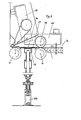
Wie aus Fig 1 zu ersehen, besteht die Vorrichtung aus einem Tragtisch 1, über dessen Auflagefläche 1a eine Lichtabdeckhaube 2 mit der Lichtquelle 3 und der lichtdurchlässigen Scheibe 4 in einem Tragrahmen 5 angeordnet sind. Über der lichtdurchlässigen Scheibe 4 ist in der Haube 2 noch ein, nicht zur Erfindung gehöriges Gitter 6 zur Erzeugung gerichteten Lichts angeordnet. Unterhalb der lichtdurchlässigen Scheibe 4 und der Ebene der Auflagefläche 1a ist eine mit elastischem Werkstoff 7 überzogene in Richtung des gezeichneten Pfeils p anhebbare Andruckstützplatte 8 angeordnet. Zwischen der lichtdurchlässigen Scheibe 4 und der Andruckstützplatte 8 wird der Endlosriemenförderer 9 bewegt; er weist vor und hinter dem durch die Haube 2 und die lichtdurchlässige Scheibe 4 gebildeten Belichtungsraum B Umlenkrollen 10 und 11 sowie eine Spannrolle 12 auf. Die in Transportrichtung T hinter der lichtdurchlässigen Scheibe 4 befindliche Umlenkrolle 10 bildet mit einer auf ihr aufliegenden Rolle 13 den Austrittsspalt und wirkt, reibangetrieben durch die Rolle 10 mit dieser als Treibwalzenpaar. Vor dem Belichtungsraum B und vor der Umlenkrolle 11 sind die Passerstifte 26 angeordnet, die - auf hier nicht dargestellte Weise - aus der gezeichneten, aus der Auflagefläche 1a herausstehenden Position in eine Position unterhalb dieser Auflagefläche 1a abgesenkt werden können. Diesen Passerstiften 26 ist in Transportrichtung T ein weiteres Treibwalzenpaar 15, 16 vorgeordnet. Die untere Treibwalze 15 des Treibwalzenpaares ist ortsfest unterhalb der Auflagefläche 1a gelagert und wird über eine in einem Wipphebel 17 gelagerte Reibzwischenrolle 18 in der gezeichneten Stellung von der Umlenkrolle 11 des Riemenförderers 9 angetrieben; sie kann durch Hubmagneten 20, der die Reibzwischenrolle in und außer Wirkungslage bringt, vom Antrieb abgeschaltet werden. Die obere Treibwalze 16 lagert (vgl. auch Fig. 2) in einem Träger 25, der in Richtung des eingezeichneten Pfeils S in die in unterbrochenen Linien dargestellte Position schwenkbar ist, wobei die Treibwalze 16 von der Auflagefläche 1a weggeschwenkt wird. Mit dem Träger 25 ist eine Andruckplatte 27 verbunden, die bei auf der Auflagefläche 1a aufliegender Treibwalze 16 ebenfalls auf dieser Auflagefläche 1a zur Auflage gelangt. Die Passerstifte 26 sind auf einer Quertraverse 29 so angeordnet, daß sie in die an beiden Längsseiten der nicht dargestellten Schichtung vorgesehenen Positionierlochungen einbringbar sind. Die Traverse 29 wird von einer nicht zur Erfindung gehörigen Magnetzugeinrichtung MZ getragen. Aus der Auflagefläche 1a ragt der Kontaktgeber 30 als Anstoßschaltelement einer nicht dargestellten Schalteinrichtung heraus, der von dem Träger 25 aus der in unterbrochenen Linien dargestellten Stellung in die in vollen Linien wiedergegebene Stellung eingebracht wird, wenn der Träger 25 die gezeichnete Position (in vollen Linien) erreicht hat und die Treibwalze 16 auf der Auflagefläche 1a bzw. der Schichtung aufliegt.As can be seen from FIG. 1, the device consists of a support table 1, over the
Die Vorrichtung arbeitet in der Weise, daß bei hochgeschwenktem Träger 25 und in oberer Position befindlichen Passerstiften 26 die Schichtung auf die Auflagefläche 1a so aufgelegt wird, daß sich die Passerstifte 26 in den Positionierlochungen befinden. Anschließend wird der Träger 25 nach unten in die in vollen Linien dargestellte Position geschwenkt, wobei sich die Andruckplatte 27 und die Treibwalze 16 auf die Schichtung auflegen und damit die die Schichtung bildenden Teile zueinander lagefixieren. Anschließend werden die Passerstifte 26 nach unten aus den Positionierlochungen heraus unter die Auflagefläche 1a bewegt und erst dann durch Betätigung des Hubmagneten 20 über die Reibzwischenrolle 18 die untere Treibwalze 15 in Umdrehung versetzt; sie transportiert dann zusammen mit der aufliegenden Treibwalze 16 die von der Andruckplatte 27 gegen die Auflagefläche 1a gedrückte Schichtung in den Belichtungsraum B unter die lichtdurchlässige Scheibe 4. Eine Querverschiebung der Teile der Schichtung gegeneinander ist während dieses Transportschrittes praktisch ausgeschlossen, da die Schichtung, bevor sie das Treibwalzenpaar 15, 16 verläßt, bereits von dem Riemenförderer 9 erfaßt worden ist und dabei zwischen Andruckstützplatte 8 und lichtdurchlässiger Scheibe 4 so geführt wird, daß Querverschiebungen der Schichtungsteile nicht mehr möglich sind. Der Antrieb der Treibwalzen 15, 16 über die Reibzwischenrolle 18 durch die Umlenkrolle 11 des Riemenförderers 7 stellt sicher, daß die Transportbewegung synchron erfolgt.The device works in such a way that when the
Die Treibwalzen 15, 16 bewirken nicht nur, daß die Teile der Schichtung gegen Querverschiebung gesichert in Richtung auf den Belichtungsraum B transportiert werden, sondern walzen auch etwaige Luftblasen, Falten oder andere Unebenheiten aus der Vorlage (Originalfilm) heraus, bevor diese in den Belichtungsraum B gelangen.The
Die einzelnen Bewegungsabläufe innerhalb der Vorrichtung werden zweckmäßig mit Hilfe von nicht zur Erfindung gehörigen Schaltelementen, wie Mikroschalter, elektronische Schaltverzögerungseinrichtungen u.dgl. gesteuert, so daß erst die Andruckplatte 27 dann die Treibwalze 16 in Verbindung mit der Treibwalze 15 die Schichtung lagefixiert und anschließend die Passerstifte 26 aus den Positionierlochungen herausbewegt werden und dann der Hubmagnet 20 betätigt wird, der die Antriebsbewegung der Treibwalze 15 veranlaßt. Der die Treibwalze 16 tragende Träger 25 kann dabei automatisch in die obere Schwenklage gebracht werden, sobald das rückwärtige Ende der Schichtung in den Belichtungsraum B eintritt, damit die nächste Schichtung möglichst schnell aufgelegt und in der beschriebenen Weise weitertransportiert werden kann.The individual movements within the device are expedient with the help of switching elements not belonging to the invention, such as microswitches, electronic switching delay devices and the like. controlled so that only the
Die Trennung der Teile der den Belichtungsraum B verlassenden Schichtung, z.B. der Druckplatte von der Vorlage erfolgt mit Hilfe einer ebenfalls nicht zur Erfindung gehörigen, hier mit einer Blasvorrichtung 30 ausgestatteten Trenneinrichtung (vgl. Fig. 1), deren Blasstrahl die Vorderkante der aus dem durch die Umlenkrolle 10 und die Walze 13 gebildeten Austrittsspalt verlassenden Schichtung beaufschlagt, mit der Wirkung, daß die Vorlage nach oben abgelenkt in eine Umlenkführung 31 gelangt und die Platte von einem Treibwalzenpaar 32 erfaßt und in Richtung des Pfeils R abtransportiert wird.The separation of the parts of the stratification leaving the exposure space B, e.g. the printing plate from the template is made with the aid of a separating device (cf. FIG. 1), which is also not part of the invention and is equipped here with a blowing
Claims (7)
Applications Claiming Priority (2)
| Application Number | Priority Date | Filing Date | Title |
|---|---|---|---|
| DE19853538192 DE3538192A1 (en) | 1985-10-26 | 1985-10-26 | DEVICE FOR PUTTING COPY AND EXPOSURE LAYERS INTO A DEVICE FOR CONTINUOUSLY EXPOSING THIS GOOD |
| DE3538192 | 1985-10-26 |
Publications (2)
| Publication Number | Publication Date |
|---|---|
| EP0244464A1 EP0244464A1 (en) | 1987-11-11 |
| EP0244464B1 true EP0244464B1 (en) | 1990-04-11 |
Family
ID=6284581
Family Applications (1)
| Application Number | Title | Priority Date | Filing Date |
|---|---|---|---|
| EP86906760A Expired - Lifetime EP0244464B1 (en) | 1985-10-26 | 1986-10-27 | Device for inserting copy and exposure material layers into a device for the continual exposure of this material |
Country Status (4)
| Country | Link |
|---|---|
| US (1) | US4786950A (en) |
| EP (1) | EP0244464B1 (en) |
| DE (2) | DE3538192A1 (en) |
| WO (1) | WO1987002788A1 (en) |
Families Citing this family (2)
| Publication number | Priority date | Publication date | Assignee | Title |
|---|---|---|---|---|
| US5923411A (en) * | 1997-06-27 | 1999-07-13 | Eastman Kodak Company | Photographic printer with mechanism for placing contact print slide at paper print gate |
| BE1027383B1 (en) | 2019-06-20 | 2021-01-28 | Vandewiele Nv | DEVICE AND METHOD FOR DETECTING DEVIATIONS IN POLAR FORMATION IN A LIFE |
Family Cites Families (9)
| Publication number | Priority date | Publication date | Assignee | Title |
|---|---|---|---|---|
| US1682979A (en) * | 1924-03-28 | 1928-09-04 | Mantor Inc | Motion-picture-printing mechanism |
| US2654300A (en) * | 1949-05-24 | 1953-10-06 | Dexter Folder Co | Photoprinting apparatus |
| GB1162768A (en) * | 1966-11-01 | 1969-08-27 | Gaf Corp | Photographic Apparatus for Contact Printing of Web Materials |
| GB1186950A (en) * | 1967-06-23 | 1970-04-08 | Agfa Gevaert Ag | Continuous Photographic Printing Apparatus |
| US3771871A (en) * | 1971-10-04 | 1973-11-13 | Du Pont | Apparatus for forming images on continuously moving elements |
| US3814519A (en) * | 1971-12-29 | 1974-06-04 | Capitol Reproductions | Photographic exposure apparatus |
| US4281922A (en) * | 1978-11-14 | 1981-08-04 | Fuji Photo Film Co., Ltd. | Plate feeding apparatus for printing apparatus |
| US4423955A (en) * | 1982-03-26 | 1984-01-03 | Western Litho Plate & Supply Co. | Photographic printing apparatus |
| DE3220637A1 (en) * | 1982-06-02 | 1983-12-08 | Hans 6250 Limburg Haus | DEVICE FOR INPUTING, OUTPUTING AND SEPARATING COPY AND EXPOSURE COATINGS |
-
1985
- 1985-10-26 DE DE19853538192 patent/DE3538192A1/en not_active Withdrawn
-
1986
- 1986-10-27 EP EP86906760A patent/EP0244464B1/en not_active Expired - Lifetime
- 1986-10-27 US US07/072,260 patent/US4786950A/en not_active Expired - Fee Related
- 1986-10-27 DE DE8686906760T patent/DE3670381D1/en not_active Expired - Lifetime
- 1986-10-27 WO PCT/DE1986/000433 patent/WO1987002788A1/en active IP Right Grant
Also Published As
| Publication number | Publication date |
|---|---|
| DE3538192A1 (en) | 1987-04-30 |
| US4786950A (en) | 1988-11-22 |
| WO1987002788A1 (en) | 1987-05-07 |
| EP0244464A1 (en) | 1987-11-11 |
| DE3670381D1 (en) | 1990-05-17 |
Similar Documents
| Publication | Publication Date | Title |
|---|---|---|
| DE3546749C2 (en) | ||
| DE3700959C2 (en) | Sheet collecting device | |
| DE2922135C2 (en) | Device for the optional deflection of a material web cut in the transverse direction | |
| DE3728516A1 (en) | NEGATIVE CARRIER ARRANGEMENT FOR USE IN A PHOTOGRAPHIC PRINTER | |
| EP0244464B1 (en) | Device for inserting copy and exposure material layers into a device for the continual exposure of this material | |
| EP0110940B1 (en) | Device for introducing, extracting and separating films of photosensitive material or copying material | |
| DE1772760A1 (en) | Copier for successive copying of a number of originals | |
| DE102020006799A1 (en) | Device for turning panels | |
| DE3036006A1 (en) | TRANSPORT DEVICE FOR A BOOK PAD ON AN ELECTROPHOTOGRAPHIC COPIER | |
| DE4038516A1 (en) | METHOD FOR MOVING EDGE-FLOORED STRIP OR PLATE-SHAPED WORKPIECES ON A LOW-FRICTION WORKPIECE SUPPORT, AND DEVICE FOR CARRYING OUT THIS PROCESS | |
| DE3523268C2 (en) | ||
| DE4432124C2 (en) | Device for separating magazine remit ends from the bottom of a stack | |
| DE2638695B2 (en) | Device for feeding and electrostatically holding image originals for copiers | |
| DE19948704C1 (en) | Unit for combined transporting and turning a horizontal stack of paper sheets, comprises a displaceable and rotatable disk and a fixed holding-down plate whose surface has a lower coefficient of friction | |
| DE3207903C2 (en) | System for exposing photopolymer materials | |
| DE3211451A1 (en) | Ergonomic poster-inscribing device with a mosaic writing unit | |
| DE3428863A1 (en) | Glass breaking machine | |
| DE1238045B (en) | Device for the successive delivery of individual sheets from a stack of sheets | |
| DE3105415A1 (en) | Device for conveying rigid, flat printing products | |
| DE2247566B2 (en) | Device for aligning an original | |
| DE4012517A1 (en) | FOLDING AND FEEDING DEVICE | |
| DE2255121C3 (en) | Device for separating sets of forms | |
| DE1786545C3 (en) | Stacking table for a duplicator or copier | |
| DE2152307A1 (en) | Method and device for positioning sheet material | |
| DE2715506A1 (en) | Form printing machine esp. for cash register - causes rollers to eject receipt when mechanism is lowered to clear |
Legal Events
| Date | Code | Title | Description |
|---|---|---|---|
| PUAI | Public reference made under article 153(3) epc to a published international application that has entered the european phase |
Free format text: ORIGINAL CODE: 0009012 |
|
| AK | Designated contracting states |
Kind code of ref document: A1 Designated state(s): CH DE FR GB LI NL SE |
|
| 17P | Request for examination filed |
Effective date: 19871106 |
|
| 17Q | First examination report despatched |
Effective date: 19890505 |
|
| GRAA | (expected) grant |
Free format text: ORIGINAL CODE: 0009210 |
|
| AK | Designated contracting states |
Kind code of ref document: B1 Designated state(s): CH DE FR GB LI NL SE |
|
| REF | Corresponds to: |
Ref document number: 3670381 Country of ref document: DE Date of ref document: 19900517 |
|
| ET | Fr: translation filed | ||
| GBT | Gb: translation of ep patent filed (gb section 77(6)(a)/1977) | ||
| ET1 | Fr: translation filed ** revision of the translation of the patent or the claims | ||
| PG25 | Lapsed in a contracting state [announced via postgrant information from national office to epo] |
Ref country code: GB Effective date: 19901027 |
|
| PG25 | Lapsed in a contracting state [announced via postgrant information from national office to epo] |
Ref country code: SE Effective date: 19901028 |
|
| PG25 | Lapsed in a contracting state [announced via postgrant information from national office to epo] |
Ref country code: LI Effective date: 19901031 Ref country code: CH Effective date: 19901031 |
|
| PLBE | No opposition filed within time limit |
Free format text: ORIGINAL CODE: 0009261 |
|
| STAA | Information on the status of an ep patent application or granted ep patent |
Free format text: STATUS: NO OPPOSITION FILED WITHIN TIME LIMIT |
|
| 26N | No opposition filed | ||
| PG25 | Lapsed in a contracting state [announced via postgrant information from national office to epo] |
Ref country code: NL Effective date: 19910501 |
|
| NLV4 | Nl: lapsed or anulled due to non-payment of the annual fee | ||
| GBPC | Gb: european patent ceased through non-payment of renewal fee | ||
| PG25 | Lapsed in a contracting state [announced via postgrant information from national office to epo] |
Ref country code: FR Effective date: 19910628 |
|
| REG | Reference to a national code |
Ref country code: CH Ref legal event code: PL |
|
| PG25 | Lapsed in a contracting state [announced via postgrant information from national office to epo] |
Ref country code: DE Effective date: 19910702 |
|
| REG | Reference to a national code |
Ref country code: FR Ref legal event code: ST |
|
| EUG | Se: european patent has lapsed |
Ref document number: 86906760.3 Effective date: 19910603 |