EP0244091A2 - Gerät zur Auswahl der Navigationsbetriebsart - Google Patents
Gerät zur Auswahl der Navigationsbetriebsart Download PDFInfo
- Publication number
- EP0244091A2 EP0244091A2 EP87302763A EP87302763A EP0244091A2 EP 0244091 A2 EP0244091 A2 EP 0244091A2 EP 87302763 A EP87302763 A EP 87302763A EP 87302763 A EP87302763 A EP 87302763A EP 0244091 A2 EP0244091 A2 EP 0244091A2
- Authority
- EP
- European Patent Office
- Prior art keywords
- navmode
- error
- estimated
- navigation
- ins
- Prior art date
- Legal status (The legal status is an assumption and is not a legal conclusion. Google has not performed a legal analysis and makes no representation as to the accuracy of the status listed.)
- Granted
Links
Images


Classifications
-
- G—PHYSICS
- G01—MEASURING; TESTING
- G01C—MEASURING DISTANCES, LEVELS OR BEARINGS; SURVEYING; NAVIGATION; GYROSCOPIC INSTRUMENTS; PHOTOGRAMMETRY OR VIDEOGRAMMETRY
- G01C21/00—Navigation; Navigational instruments not provided for in groups G01C1/00 - G01C19/00
- G01C21/10—Navigation; Navigational instruments not provided for in groups G01C1/00 - G01C19/00 by using measurements of speed or acceleration
- G01C21/12—Navigation; Navigational instruments not provided for in groups G01C1/00 - G01C19/00 by using measurements of speed or acceleration executed aboard the object being navigated; Dead reckoning
- G01C21/16—Navigation; Navigational instruments not provided for in groups G01C1/00 - G01C19/00 by using measurements of speed or acceleration executed aboard the object being navigated; Dead reckoning by integrating acceleration or speed, i.e. inertial navigation
- G01C21/183—Compensation of inertial measurements, e.g. for temperature effects
- G01C21/188—Compensation of inertial measurements, e.g. for temperature effects for accumulated errors, e.g. by coupling inertial systems with absolute positioning systems
-
- G—PHYSICS
- G01—MEASURING; TESTING
- G01C—MEASURING DISTANCES, LEVELS OR BEARINGS; SURVEYING; NAVIGATION; GYROSCOPIC INSTRUMENTS; PHOTOGRAMMETRY OR VIDEOGRAMMETRY
- G01C21/00—Navigation; Navigational instruments not provided for in groups G01C1/00 - G01C19/00
- G01C21/005—Navigation; Navigational instruments not provided for in groups G01C1/00 - G01C19/00 with correlation of navigation data from several sources, e.g. map or contour matching
-
- G—PHYSICS
- G01—MEASURING; TESTING
- G01C—MEASURING DISTANCES, LEVELS OR BEARINGS; SURVEYING; NAVIGATION; GYROSCOPIC INSTRUMENTS; PHOTOGRAMMETRY OR VIDEOGRAMMETRY
- G01C21/00—Navigation; Navigational instruments not provided for in groups G01C1/00 - G01C19/00
- G01C21/10—Navigation; Navigational instruments not provided for in groups G01C1/00 - G01C19/00 by using measurements of speed or acceleration
- G01C21/12—Navigation; Navigational instruments not provided for in groups G01C1/00 - G01C19/00 by using measurements of speed or acceleration executed aboard the object being navigated; Dead reckoning
- G01C21/16—Navigation; Navigational instruments not provided for in groups G01C1/00 - G01C19/00 by using measurements of speed or acceleration executed aboard the object being navigated; Dead reckoning by integrating acceleration or speed, i.e. inertial navigation
- G01C21/165—Navigation; Navigational instruments not provided for in groups G01C1/00 - G01C19/00 by using measurements of speed or acceleration executed aboard the object being navigated; Dead reckoning by integrating acceleration or speed, i.e. inertial navigation combined with non-inertial navigation instruments
-
- G—PHYSICS
- G01—MEASURING; TESTING
- G01S—RADIO DIRECTION-FINDING; RADIO NAVIGATION; DETERMINING DISTANCE OR VELOCITY BY USE OF RADIO WAVES; LOCATING OR PRESENCE-DETECTING BY USE OF THE REFLECTION OR RERADIATION OF RADIO WAVES; ANALOGOUS ARRANGEMENTS USING OTHER WAVES
- G01S5/00—Position-fixing by co-ordinating two or more direction or position line determinations; Position-fixing by co-ordinating two or more distance determinations
- G01S5/02—Position-fixing by co-ordinating two or more direction or position line determinations; Position-fixing by co-ordinating two or more distance determinations using radio waves
Definitions
- the invention relates to navigation systems particularly with respect to multiple mode, multiple sensor area navigation systems (RNAV) for aircraft.
- RNAV multiple sensor area navigation systems
- Navigation systems for aircraft traditionally utilise a plurality of navigation sensors (navaids) and operate in a plurality of navigation modes (navmodes).
- radio aids such as FOR (VHF Omni Range) and DME (Distance Measuring Equipment) for airport-to-airport navigation and localisers for terminal guidance are utilised.
- the aircraft is often equipped with onside (leftside) radio receivers and offside (rightside) receivers for these radio navaids.
- the navigation system aboard present day aircraft often includes an inertial navigation system (INS) or an inertial reference system (IRS).
- INS inertial navigation system
- IRS inertial reference system
- Such navigation systems operate in a plurality of modes variously utilising the navaid sensor complement.
- Such traditional modes include RHO-RHO, BEELINE, RHO-THETA LEFT, RHO-THETA RIGHT, LOCALIZER LEFT, LOCALIZER RIGHT, INS and DEAD RECKONING.
- RHO-RHO and BEELINE navigation the aircraft position is determined utilising two DME distances where each DME sensor provides range from a known reference point.
- the aircraft position is generated utilising the VOR bearing and DME distance from a known reference point, the bearing and distance data being provided by the leftside VOR and DME sensors.
- the RHO-THETA RIGHT navigation mode is similar to the RHO-THETA LEFT mode except that the bearing and distance data is provided by the rightside VOR and DME sensors.
- the LOCALISER modes lateral displacement from a localiser beam is provided by beam error data from the onside or offside localiser in accordance with the navigation mode utilised.
- the aircraft position is set equal to the position output of the INS.
- the aircraft position is set equal to the position determined from the DEAD RECKONING algorithm utilised.
- Such multiple-mode, multiple-sensor navigation systems traditionally select the sensors and modes to be utilised in position computations in accordance with a predetermined procedure.
- a fixed hierarchy of priorities is established for navigation mode selection and sensor usage. For example, in an aircraft navigation system, having two VOR/DME sensors and one inertial navigation unit, the hierarchy of navigation modes and sensor usage might be established in the following order: RHO-RHO, RHO-THETA LEFT, RHO-THETA RIGHT, and INS.
- the flight crew aligns the INS. Shortly after the aircraft becomes airborne, the leftside VOR and DME sensors receive valid radio navigation distance and bearing data from a single distant VOR/DME station. Under the fixed hierarchy described above, the RHO-THETA LEFT mode is selected as the highest priority navigation mode. This is undesirable because RHO-THETA navigation performed using a distant VOR/DME station typically results in a position computation that is less accurate than the position provided by a recently aligend INS. The INS, however, tends to drift with time. It is very accurate at the beginning of a flight, but tends to become increasingly more inaccurate as time increases.
- RHO-THETA navigation may or may not provide a more accurate position estimate at that time. Additionally, if for example, the prior art system is performing RHO-RHO navigation when criteria for RHO-RHO navigation can no longer be fulfilled, the system reverts to RHO-THETA navigation, providing RHO-THETA criterial can be met. However, under these conditions, a more accurate position estimate is achievable by utilising the radio corrected INS or DEAD RECKONING, for at least a short time, from the last RHO-RHO computed position.
- the shortcomings of prior art navigation systems are overcome by the navigation system, implemented in accordance with the present invention, capable of operating in multiple navigation modes, each mode utilising appropriate navigation sensors.
- the invention is defined in the appended claims and includes means for generating the expected or estimated navmode position error for each of the navigation modes and means for selecting the navigation mode having the smallest value of the estimated navmode error consistent with procedure specified navaid criteria.
- the invention further includes means for generating the aircraft position pursuant to the selected mode with a low pass, slow-in position filter processing the position data provided by the selected mode. The position filter prevents undesired instantaneous changes in aircraft position output when switching from one navigation mode to another.
- An identical filter is utilised to process the estimated navmode error for the selected mode to obtain an estimated position error that provides an estimate of the magnitude of the difference between the output position of the navigation system and the true aircraft position.
- This estimated position error is utilised to estimate the navmode errors to compute a correction factor for correcting the INS and DEAD RECKONING navigation modes.
- the estimated position error is also utilised for sensor data validation in the performance of data reasonableness tests.
- the data reasonableness tests are performed by requiring that the difference between estimated sensor data based on assumed position calculated by the navigation system and actual sensor data which is a function of true position be below a threshhold.
- the threshhold is selected as a function of estimated position error, thereby permitting lower thresholds to be utilised than were possible in the prior art.
- the invention therefore, provides an improved ability to reject bad sensor data by utilising more stringent data reasonableness tests.
- the navigation system implemented in accordance with the present invention provides a more accurate position output than was possible in the prior art by recognising the dynamic quality of navigation mode/sensor combinations; generating the estimated value of the mode/sensor error for each combination and implementing the navmode with the smallest value of estimated error consistent with procedures specified for the navaids.
- FIG. l a multiple-mode, multiple-sensor navigation system implementing the concepts of the present invention is illustrated.
- the system of Figure l is capable of operating in a plurality of distinct navigation modes, each navmode utilising appropriate navigation sensors.
- a plurality of navmode error estimators l0-l6 provide estimated navmode position error signals associated respectively with the navmodes supported by the system.
- the estimated navmode error signals from the estimators l0-l6 are applied to a navigation mode selector l7 which is also responsive to signals representative of FAA (U.S. Federal Aviation Authority) procedure specified navaid criteria.
- the navigation mode selector l7 selects the navigation mode having the lowest value of estimated navmode error which is consistent with the FAA procedure specified navaid criteria signal.
- the navigation mode selector l7 provides a select navmode signal on a lead l8 representative of the selected navmode.
- the signal on the lead l8 is applied to an aircraft position computation block l9 wherein aircraft position is computed in accordance with the selected navmode.
- the aircraft position computation block l9 provides the following navmodes: RHO-RHO, RHO-THETA, LOCALISER, INS, AND DEAD RECKONING as indicated by the reference numerals 20-24 respectively. It will be appreciated that the signal on the lead l8 selects one of the computations 20-24 in accordance with the outputs of the error estimators l0-l6 and the FAA procedure specified navaid criteria signal applied to the navigation mode selector l7.
- Each of the navmode computations 20-24 is responsive to appropriate sensor data and information from the navigation data base for computing the aircraft position in accordance with the selected navmode.
- the computed aircraft position signal is provided on a lead 25 via a low pass position filter 26.
- the low pass position filter 26 implements a slow-in type of function whereby abrupt changes in computed aircraft position cannot occur when switching navigtion modes.
- the position filter 26 is illustrated at the output of the aircraft position computation block l9, it will be appreciated that the filtering may alternatively be provided within the blocks 20-24 to the same effect.
- the navigation mode selector l7 provides the estimated navmode error on a lead 27 generated by the error estimator l0-l6 associated with the selected navmode.
- the estimated navmode error signal on the lead 27 is processed through a low-pass position error filter 28 to provide an estimated position error signal on a lead 29.
- the position error filter 28 has the same time constant as the position filter 26 and has a transfer function of the form [a/s+a)].
- the estimated position error on the lead 29 is an accurate estimate of the probable error in position at any given time. It will be appreciated that there is a distinction between the estimated navmode errors and the estimated position error on the lead 29.
- Navmode errors are associated with a particular navigation mode and are the outputs of the error estimators l0-l6.
- Position error is the estimate of the magnitude of the difference between the position computed by the system of Figure l and the actual aircraft position.
- the estimated position error on the lead 29 is utilised in the calculation of INS and DEAD RECKONING correction factors and in the computation of the estimated navmode errors for the INS error estimator l5 and the DEAD RECKONING error estimator l6 so as to correct the INS and DEAD RECKONING navigation modes in a manner to be described.
- the estimated position error on the lead 29 is also utilised to perform sensor data validation via data reasonableness testing in a block 30 which is also responsive to the computed aircraft position on the lead 25. Data reasonableness tests are performed on the raw VOR and DME data applied as input to the block 30 to provide validated VOR and DME data to the outputs thereof in a manner to be explained.
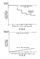
- the error estimator l0 provides the estimated MULTIRHORHO navmode error for the MULTIRHORHO navmode.
- the error function for the MULTIRHORHO navmode error is illustrated in Figure 2.
- the MULTIRHORHO navmode utilises signals received from plural DME stations.
- Preferably ARINC 709 scanning DME equipment provides the DME information required to perform the MULTIRHORHO navigation. Errors in position computation utilising MULTIRHORHO navigation are a function of the error models for each DME, the number of DME stations utilised and the geometry.
- the MULTIRHORHO error estimation may be performed solely as a function of the number of DME stations being utilised. If less than two usable DME stations (RHORHO case) are available, or geometry requirements are not met, the error estimator lO sets the estimated navmode error to an arbitrarily large value. Otherwise, the error estimator lO sets the estimated navmode error to O.5 nautical miles (NM) for two usable DME stations and decreases the estimated error to O.325 NM for five usable DME stations.
- NM nautical miles
- a usable DME station is one that is validated by passing the data reasonableness tests of the block 30 and that meets minimum DME range criteria.
- a suitable range criterion is that the distance from the DME station to the aircraft is greater than l.94 times the estimated position error on the lead 29. It will be appreciated from Figure 2 that the error function is non-linear. This non-linearity results because each additional usable DME station provides a marginal decrease in error which is smaller than the decrease provided by the addition of the previous DME station.
- BEELINE navigation may be utilised in the system of the present invention instead of MULTIRHORHO navigation.
- the estimated BEELINE navmode error is derived in the same manner as the estimated MULTIRHORHO navmode error except that the error is also a function of an initial position estimate and the number of iterations performed.
- the BEELINE error estimation may also be simplified by utilising solely a function of the number of DME stations.
- the error function of Figure 2 is additionally applicable to the BEELINE navmode error.
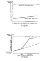
- the error estimators ll and l2 provide the estimated RHO-THETA navmode error for the RHO-THETA LEFT and RHO-THETA RIGHT navmodes, respectively.
- the error function for the estimated RHO-THETA navmode error is provided in Figure 3.
- the present embodiment supports two RHO-THETA navigation modes, RHO-THETA utilising the onside VOR and RHO-THETA utilising the offside VOR. In both modes of navigation, the ARINC 709 scanning DME provides the DME information required to perform the RHO-THETA navigation.
- the estimated RHO-THETA navmode error provided by the error estimator ll is a function of the distance of the aircraft to any type of navaid tuned on the left radio.
- the estimated RHO-THETA navmode error provided by the error estimator l2 is a function of the distance of the aircraft to any type of navaid tuned on the right radio.
- the error estimators ll and l2 provide their respective estimated navmode error signals for the RHO-THETA LEFT and RHO-THETA RIGHT navigation modes.
- the error estimates for RHO-THETA navigation utilising the onside or offside VOR/DME are generated as follows. If the navigation radio receiver is tuned to a navaid that has a VOR only, or if the receiver is tuned to a VOR/DME navaid, but the VOR and DME are not both valid, the estimated navmode error is set to an arbitrarily large value.
- ⁇ P ⁇ ( ⁇ R)2 + [R ( ⁇ ]2 ⁇ 1/2
- ⁇ P Position Error (NM)
- NM DME ground range (NM)
- NM DME range error (NM)
- the error estimator l2 of Figure l for computing the estimated navmode error for the RHO-THETA offside navmode adds a small positive bias to the estimated navmode error. This assures that if both the onside and offside receivers are tuned to the same navaid, the system will select the onside VOR receiver when performing RHO-THETA navigation. If the VOR receivers are tuned to different VOR stations, the system includes means (not shown) for selecting the closest valid VOR/DME when performing RHO-THETA navigation.
- the error estimator l3 provides the estimated navmode error for the LOCALISER LEFT navigation mode as a function of meeting minimum requirements for LOCALISER updating on the left.
- the error estimator l4 provides the estimated navmode error for the LOCALISER RIGHT navmode as a function of meeting the minimum requirements for LOCALISER updating on the right.
- the LOCALISER navmode provides very accurate navigation during final approach and missed approach procedures. The criteria that must be achieved before LOCALISER navigation can be performed are very stringent, but when these criteria are met, LOCALISER navigation can provide navigational accuracy of better than O.l NM.
- the estimated navmode error function for LOCALISER LEFT navigation or LOCALISER RIGHT navigation is generated utilising the following process.
- the estimated navmode errors for both onside and offside LOCALISER navigation are set to an arbitrarily large value and the estimated navmode error for onside LOCALISER navigation is generated as follows.
- the aircraft position is within 20 NM of the LOCALISER, and the bearing from the aircraft position to the LOCALISER is within ten degrees of the LOCALISER centre beam, and the aircraft track is within thirty degrees of the LOCALISER centre beam, and the LOCALISER deviation is less than l.25 degrees; then the estimated navmode error for the onside LOCALISER navmode is set to O.l NM. If any of these conditions are not met, the estimated navmode error remains at the arbitrarily large value.
- ILS instrument landing system
- the estimated navmode error for onside LOCALISER navigation remains at the maximum value, then the estimated navmode error for offside LOCALISER navigation is generated utilising the same function. Otherwise, the estimated navmode error for offside LOCALISER navigation remains at the maximum value. This procedure ensures that offside LOCALISER navigation will never be performed when onside LOCALISER navigation is possible.
- the error estimator l5 generates the estimated INS navmode error as a function of the estimated position error signal on the lead 29, the inertial navigation system error, the inertial navigation system drift rate, and the inertial navigation system alignment time.
- the error function for the estimated INS navmode error (with last known radio or flight crew correction) is illustrated in Figure 4.
- the estimated navmode error function for the corrected INS navigation mode is generated in the following manner.
- the flight crew pilot or navigator aligns the INS
- the alignment is assumed to be fairly accurate and the estimated INS navmode error is initialised to an appropriate small value, for example, 0.5 NM.
- the estimated INS navmode error is set to the estimated position error, thereby providing a recomputed INS correction bias. If, however, the estimated position error on the lead 29 is not less than the current estimated INS navmode error, the estimated INS navmode error is increased at the drift rate of the INS, for example 2 NM/HR.
- the estimated position error on the lead 29 is utilised by the INS error estimator l5 to provide an INS correction bias to be utilised in the block 23 to correct the INS position, In this manner, the excellent short-term characteristics of the INS system are utilised corrected for long-term INS drift.
- the estimated INS navmode error will be set to: 2 NM + [2 NM/HR ⁇ (time in hours since alignment)] If the navigation system is not equipped with an INS, or if the INS has failed, the estimated INS navmode error is set to an arbitrarily large value.
- the error estimator l6 provides the estimated DEAD RECKONING navmode error in accordance with a function of the estimated position error on the lead 29, the DEAD RECKONING error, and the DEAD RECKONING drift rate.
- the error function for the estimated DEAD RECKONING navmode error (from last known position or with last known radio correction) is illustrated in Figure 5.
- the estimated navmode error function for DEAD RECKONING is similar to the estimated INS navmode error function described above except that instead of utilsing INS drift rate, a higher "DEAD RECKONING drift rate" is utilised.
- the estimated DEAD RECKONING navmode error is set to the estimated position error.
- the DEAD RECKONING estimated navmode error is increased from the previous value at the appropriate DEAD RECKONING drift rate as determined by the curve of Figure 5.
- the dashed line curve of Figure 5 represents the assumption that the estimated navmode error is increased from the previous value at the rate of the expected average difference between the last known winds and the actual winds during the time that the system is in the DEAD RECKONING mode.
- the solid line curve of Figure 5 represents the assumption that the longer the aircraft DEAD RECKONS, the less accurate the wind estimate becomes. Therefore, when the DEAD RECKONING error is small (previous navmode was good and therefore the derived wind estimate is good), the drift rate is low, for example 20 NM/HR. When the DEAD RECKONING error is large (previous navmode was not good and therefore the wind estimate may be questionable or the aircraft has been DEAD RECKONING with an old wind estimate), the drift rate is high, for example l25 NM/HR.
- DEAD RECKONING may be considered as an economy INS or, alternatively, an INS can be considered as a very accurate DEAD RECKONING system.
- the navigation mode selector l7 selects the navmode having the minimum estimated navmode error that satisfied any procedure specified requirements. If, for example, the FAA prohibits the use of a particular VOR, the VOR navmodes are not enabled. Specifically, the navigation mode selector l7 tentatively selects the navigation mode having the lowest value of estimated navmode error. If there is a procedure specified navaid for the active leg, and the tentatively selected navigation mode does not utilise the procedure specified navaid, the navigation mode selector l7 attempts to identify a valid navigation mode having the lower value of estimated navmode error and which satisfies the procedure specified requirements. If such a mode is identified, it is selected. If a navigation mode satisfying the procedure specified requirements cannot be identified, or if there is not a procedure specified navaid for the active leg, then the tentative navigation mode is selected.
- the estimated position error signal on the lead 29 is utilised in the generation of the estimated navmode errors for the DEAD RECKONING and INS navmode error estimators.
- the estimated position error is also utilised in driving the data reasonableness tests implemented in the block 30.
- the data reasonableness tests are tightened or expanded in accordance with the confidence in position represented by the estimated position error signal.
- DME The actual distance from the DME to the true position as obtained from the input DME data
- DIST APRX The distance from the DME to the navigation system position as provided on the lead 25.
- the data validation tests for the VOR data is implemented in the block 30 whereby the VOR data is validated if:
- BRG VOR The magnetic bearing as received from the VOR
- BRG APRX is the expected bearing from the VOR to the navigation system position as provided on the lead 25.
- the estimated position error signal on the lead 29 is a measure of the error in the computed aircraft position at any time. If the position data provided by the VOR or DME is greater than this error, the data is considered invalid and the affected navmodes are disabled. It will be appreciated that similar data reasonableness tests may be derived and utilised for other navigation sensors.
- the estimated position error signal on the lead 29 is utilised to provide a correction factor for the INS and DEAD RECKONING navigation modes as well as in determining the validity threshold in the data reasonableness tests block 30.
- the estimated position error may also be utilised to set the minimum DME range of criteria to assure conversion of the BEELINE navmode.
- Navigation systems utilising the RHO-RHO navmode generally have a minimum leg length requirement that could be made less restrictive if it were a function of estimated position error.
- the estimated position error signal may also be utilised in installations having dual navigation systems for system-to-system position comparisons. Additionally, the estimated position error may be displayed to the pilot or navigator as a measure of navigation system performance.
- the aircraft position computation block l9 provides computed aircraft position in response to appropriate navigation sensor data and information from the navigation data base.
- the aircraft position computation block l9 is responsive to VOR data from the left and right VOR receivers, DME data from the left and right DME receivers, LOCALISER data from the left and right LOCALISER receivers and INS data from the INS system.
- the aircraft position computation block l9 is also responsive to the estimated navmode error from the error estimator l5 for providing a radio correction bias for the INS position as well as to the estimated navmode error from the error estimator l6 for providing a position correction in the DEAD RECKONING computation.
- the position computation blocks 20-24 utilise conventional procedures for providing computed aircraft position, numerous suitable procedures being available in the art for use in the present invention.
- a MULTIRHORHO procedure for use in block 20 may be implemented as follows.
- the ARINC 709 DME equipment provides l0 possible navaid pair permutations and the MULTIRHORHO procedure selects two DME navaids. When more than one navaid pair is usable, a different pair is selected every time MULTIRHORHO is executed.
- MULTIRHORHO defaults to RHO-RHO navigation with one navaid pair.
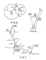
- a RHO-RHO navigation procedure is diagrammed in Figure 6. Given two DME facilities, with known locations, elevations, slant range from each of the facilities to the aircraft and the aircraft altitude, aircraft position is determined as follows. Slant range, station elevation and aircraft altitude are utilised to compute ground ranges Dl and D2. The two DME facilities and their associated ground ranges determine two circles which intersect at points Pl and P2. The aircraft position is either at Pl or P2. The ambiguity is resolved by comparing the bearing from DMEl to Pl with the bearing from DMEl to the last estimate of aircraft position. If the difference between these bearings is less than 30 degrees, Pl is assumed to be the actual aircraft position, otherwise, P2 is assumed to be the actual aircraft position. The angle THETA is restricted to be in the range 3O to l5O degrees. With this restriction, the procedure provides the correct position provided that Dl and D2 are both greater than l.94 times the difference between the estimated position and actual aircraft position.
- BEELINE navigation may be utilised instead of MULTIRHORHO or RHO-RHO navigation.
- FIG 7 several iterations of the BEELINE procedure are illustrated. It will be appreciated that on each successive iteration, the computed aircraft position becomes closer to the actual aircraft position. Given a DME distance to each of two or more DME ground stations, each having a known location and an initial position estimate P(N), position updates are generated by the BEELINE procedure as follows:
- the aircraft position is computed as follows.
- the DME slant range is converted to ground range and the magnetic variation for the VOR location is added to the VOR bearing to convert the VOR bearing to a true bearing.
- the computed aircraft position Pl is then generated utilising Sodano's geodesic equations.
- the estimated navmode error and the estimated position error for the flight plan is illustrated. It will be appreciated that the flight plan is not "typical", but rather an example constructed to illustrate transitions between the navigation modes supported by the embodiment described above. During a typical commercial service flight, it is expected that the selected navmode will be MULTIRHORHO or BEELINE over most of the flight with occasional reversions to INS (or DEAD RECKONING for non-INS equipped aircraft).
- the estimated navmode error diagram of Figure 9 and the estimated position error diagram of Figure l0 illustrate the flight scenario wherein various navigation modes and sensor combinations are selected.
- Figure 9 illustrates the estimated navmode errors for each navmode combination.
- Figure l0 illustrates the estimated navmode error (in dashed line) for the selected navmode combination and further illustrates the resulting estimated position error in solid line.
- the following ordered list of selected navigation modes correspond to the indicated points on the time axis of Figures 9 and l0.
- the present invention provides a multiple-mode, multiple-sensor navigation system with navigation mode selection determined by minimising position error.
- the error characteristics of the various navigation modes supported by the system are well known. For each navigation mode supported by the system an estimate of expected position error is generated in real time as a function of sensor data. Any navigation mode can be added to the system provided that a suitable error model therefor is available or can be developed.
- the system of the present invention in dynamic operation, avoids fequent navigation mode switching when such switching would cause the aircraft to manoeuvre.
- the present invention estimates the navigation errors that would be introduced by each available navigation mode, and then selects the navigation mode with the lowest estimated error.
- the navigation system provides navigation that is superior to that presently in use in prior art systems.
- the data reasonableness tests of block 30 of Figure l which are predicted on the allowable difference between expected sensor data and actual sensor data, are a function of expected position error, thereby providing the navigation system with an enhanced capability to reject inaccurate navaid sensor data.
- the data reasonableness test limits are maintained as tight as possible by adjusting the limits in accordance with function of estimated position error.
- the present invention provides the capability of utilising the excellent short-term accuracy of INS and/or DEAD RECKONING navigation, thereby avoiding less accurate navigation modes.
Landscapes
- Engineering & Computer Science (AREA)
- Radar, Positioning & Navigation (AREA)
- Remote Sensing (AREA)
- Physics & Mathematics (AREA)
- General Physics & Mathematics (AREA)
- Automation & Control Theory (AREA)
- Navigation (AREA)
- Control Of Position, Course, Altitude, Or Attitude Of Moving Bodies (AREA)
- Position Fixing By Use Of Radio Waves (AREA)
- Traffic Control Systems (AREA)
Applications Claiming Priority (2)
| Application Number | Priority Date | Filing Date | Title |
|---|---|---|---|
| US858410 | 1986-04-30 | ||
| US06/858,410 US4806940A (en) | 1986-04-30 | 1986-04-30 | Navigation mode selection apparatus |
Publications (3)
| Publication Number | Publication Date |
|---|---|
| EP0244091A2 true EP0244091A2 (de) | 1987-11-04 |
| EP0244091A3 EP0244091A3 (en) | 1989-07-12 |
| EP0244091B1 EP0244091B1 (de) | 1993-06-16 |
Family
ID=25328252
Family Applications (1)
| Application Number | Title | Priority Date | Filing Date |
|---|---|---|---|
| EP87302763A Expired - Lifetime EP0244091B1 (de) | 1986-04-30 | 1987-03-31 | Gerät zur Auswahl der Navigationsbetriebsart |
Country Status (4)
| Country | Link |
|---|---|
| US (1) | US4806940A (de) |
| EP (1) | EP0244091B1 (de) |
| JP (1) | JP2650028B2 (de) |
| DE (1) | DE3786195T2 (de) |
Cited By (21)
| Publication number | Priority date | Publication date | Assignee | Title |
|---|---|---|---|---|
| WO1997029346A1 (fr) * | 1996-02-09 | 1997-08-14 | Sextant Avionique | Procede et dispositif d'aide a la navigation aerienne, avec affichage d'instruments de navigation utilises |
| FR2884022A1 (fr) * | 2005-04-04 | 2006-10-06 | Airbus France Sas | Procede et dispositif d'aide au controle lateral d'un avion roulant sur une piste |
| US10809388B1 (en) * | 2019-05-01 | 2020-10-20 | Swift Navigation, Inc. | Systems and methods for high-integrity satellite positioning |
| US11035961B2 (en) | 2014-10-27 | 2021-06-15 | Swift Navigation, Inc. | Systems and methods for real time kinematic satellite positioning |
| US11061141B2 (en) | 2017-11-17 | 2021-07-13 | Swift Navigation, Inc. | Systems and methods for distributed dense network processing of satellite positioning data |
| US11237276B2 (en) | 2019-08-01 | 2022-02-01 | Swift Navigation, Inc. | System and method for gaussian process enhanced GNSS corrections generation |
| US11300689B2 (en) | 2020-02-14 | 2022-04-12 | Swift Navigation, Inc. | System and method for reconverging GNSS position estimates |
| US11378699B2 (en) | 2020-07-13 | 2022-07-05 | Swift Navigation, Inc. | System and method for determining GNSS positioning corrections |
| US11480690B2 (en) | 2020-06-09 | 2022-10-25 | Swift Navigation, Inc. | System and method for satellite positioning |
| US11550067B2 (en) | 2020-12-17 | 2023-01-10 | Swift Navigation, Inc. | System and method for fusing dead reckoning and GNSS data streams |
| US11624838B2 (en) | 2020-07-17 | 2023-04-11 | Swift Navigation, Inc. | System and method for providing GNSS corrections |
| US11624843B2 (en) | 2017-12-14 | 2023-04-11 | Swift Navigation, Inc. | Systems and methods for reduced-outlier satellite positioning |
| US11681050B2 (en) | 2019-12-11 | 2023-06-20 | Swift Navigation, Inc. | System and method for validating GNSS ambiguities |
| US11693120B2 (en) | 2021-08-09 | 2023-07-04 | Swift Navigation, Inc. | System and method for providing GNSS corrections |
| US11733397B2 (en) | 2021-07-24 | 2023-08-22 | Swift Navigation, Inc. | System and method for computing positioning protection levels |
| US11860287B2 (en) | 2022-03-01 | 2024-01-02 | Swift Navigation, Inc. | System and method for detecting outliers in GNSS observations |
| US11906640B2 (en) | 2022-03-01 | 2024-02-20 | Swift Navigation, Inc. | System and method for fusing sensor and satellite measurements for positioning determination |
| US12013468B2 (en) | 2022-09-01 | 2024-06-18 | Swift Navigation, Inc. | System and method for determining GNSS corrections |
| US12019163B2 (en) | 2022-09-12 | 2024-06-25 | Swift Navigation, Inc. | System and method for GNSS correction transmission |
| US12216211B2 (en) | 2021-12-10 | 2025-02-04 | Swift Navigation, Inc. | System and method for correcting satellite observations |
| US12498493B2 (en) | 2022-10-21 | 2025-12-16 | Swift Navigation, Inc. | System and method for distributed integrity monitoring |
Families Citing this family (19)
| Publication number | Priority date | Publication date | Assignee | Title |
|---|---|---|---|---|
| US5012424A (en) * | 1989-02-22 | 1991-04-30 | Honeywell Inc. | Multiple sensor system and method |
| US5936572A (en) * | 1994-02-04 | 1999-08-10 | Trimble Navigation Limited | Portable hybrid location determination system |
| WO1998010307A1 (en) | 1996-09-09 | 1998-03-12 | Dennis Jay Dupray | Location of a mobile station |
| US6236365B1 (en) | 1996-09-09 | 2001-05-22 | Tracbeam, Llc | Location of a mobile station using a plurality of commercial wireless infrastructures |
| US9134398B2 (en) | 1996-09-09 | 2015-09-15 | Tracbeam Llc | Wireless location using network centric location estimators |
| US5923286A (en) * | 1996-10-23 | 1999-07-13 | Honeywell Inc. | GPS/IRS global position determination method and apparatus with integrity loss provisions |
| US6999779B1 (en) | 1997-02-06 | 2006-02-14 | Fujitsu Limited | Position information management system |
| US6082666A (en) * | 1997-12-03 | 2000-07-04 | Raytheon Company | System for accurately determining missile vertical velocity and altitude |
| US9875492B2 (en) | 2001-05-22 | 2018-01-23 | Dennis J. Dupray | Real estate transaction system |
| US10684350B2 (en) | 2000-06-02 | 2020-06-16 | Tracbeam Llc | Services and applications for a communications network |
| US10641861B2 (en) | 2000-06-02 | 2020-05-05 | Dennis J. Dupray | Services and applications for a communications network |
| JP3575451B2 (ja) * | 2001-09-07 | 2004-10-13 | 株式会社デンソー | 移動通信端末装置およびそのプログラム |
| FR2927455B1 (fr) * | 2008-02-08 | 2014-03-21 | Thales Sa | Procedes d'optimisation de la localisation d'un aeronef au sol et en phases de decollage et d'atterrissage |
| US8462745B2 (en) | 2008-06-16 | 2013-06-11 | Skyhook Wireless, Inc. | Methods and systems for determining location using a cellular and WLAN positioning system by selecting the best WLAN PS solution |
| JP4866951B2 (ja) * | 2009-09-16 | 2012-02-01 | 株式会社日立製作所 | 測位組み合わせ決定システム |
| US9538493B2 (en) | 2010-08-23 | 2017-01-03 | Finetrak, Llc | Locating a mobile station and applications therefor |
| US8930047B2 (en) * | 2011-07-07 | 2015-01-06 | Raytheon Company | Systems and methods for determining a positional state of an airborne array antenna using distributed accelerometers |
| US9097529B2 (en) * | 2012-07-12 | 2015-08-04 | Honeywell International Inc. | Aircraft system and method for improving navigation performance |
| US11945439B2 (en) * | 2020-02-27 | 2024-04-02 | Volvo Truck Corporation | AD or ADAS aided maneuvering of a vehicle |
Family Cites Families (7)
| Publication number | Priority date | Publication date | Assignee | Title |
|---|---|---|---|---|
| US3630079A (en) * | 1969-03-27 | 1971-12-28 | Texas Instruments Inc | Navigation method and apparatus utilizing multiple sensors |
| GB1359298A (en) * | 1971-08-20 | 1974-07-10 | Exxon Research Engineering Co | Integrated navigation systems for ships |
| US4071744A (en) * | 1976-05-13 | 1978-01-31 | Pollock Eugene J | Loop integration control system |
| JPS57159310A (en) * | 1981-03-28 | 1982-10-01 | Nissan Motor Co Ltd | Running inductive device for car |
| US4495580A (en) * | 1981-03-30 | 1985-01-22 | E-Systems, Inc. | Navigation system |
| US4571685A (en) * | 1982-06-23 | 1986-02-18 | Nec Corporation | Production system for manufacturing semiconductor devices |
| US4533991A (en) * | 1982-12-29 | 1985-08-06 | Storage Technology Corporation | Adaptive feedforward servo system |
-
1986
- 1986-04-30 US US06/858,410 patent/US4806940A/en not_active Expired - Lifetime
-
1987
- 1987-02-16 JP JP62033136A patent/JP2650028B2/ja not_active Expired - Fee Related
- 1987-03-31 EP EP87302763A patent/EP0244091B1/de not_active Expired - Lifetime
- 1987-03-31 DE DE87302763T patent/DE3786195T2/de not_active Expired - Fee Related
Cited By (36)
| Publication number | Priority date | Publication date | Assignee | Title |
|---|---|---|---|---|
| FR2744800A1 (fr) * | 1996-02-09 | 1997-08-14 | Sextant Avionique | Procede et dispositif d'aide a la navigation aerienne, avec affichage d'instruments de navigation utilises |
| WO1997029346A1 (fr) * | 1996-02-09 | 1997-08-14 | Sextant Avionique | Procede et dispositif d'aide a la navigation aerienne, avec affichage d'instruments de navigation utilises |
| FR2884022A1 (fr) * | 2005-04-04 | 2006-10-06 | Airbus France Sas | Procede et dispositif d'aide au controle lateral d'un avion roulant sur une piste |
| US7787998B2 (en) | 2005-04-04 | 2010-08-31 | Airbus France | Method and device for assisting the lateral control of an aircraft running on a runway |
| US11035961B2 (en) | 2014-10-27 | 2021-06-15 | Swift Navigation, Inc. | Systems and methods for real time kinematic satellite positioning |
| US11061141B2 (en) | 2017-11-17 | 2021-07-13 | Swift Navigation, Inc. | Systems and methods for distributed dense network processing of satellite positioning data |
| US12164041B2 (en) | 2017-11-17 | 2024-12-10 | Swift Navigation, Inc. | Systems and methods for distributed dense network processing of satellite positioning data |
| US11714196B2 (en) | 2017-11-17 | 2023-08-01 | Swift Navigation, Inc. | Systems and methods for distributed dense network processing of satellite positioning data |
| US11624843B2 (en) | 2017-12-14 | 2023-04-11 | Swift Navigation, Inc. | Systems and methods for reduced-outlier satellite positioning |
| US12366666B2 (en) | 2017-12-14 | 2025-07-22 | Swift Navigation, Inc. | Systems and methods for reduced-outlier satellite positioning |
| US12105211B2 (en) | 2019-05-01 | 2024-10-01 | Swift Navigation, Inc. | Systems and methods for high-integrity satellite positioning |
| US11372114B2 (en) | 2019-05-01 | 2022-06-28 | Swift Navigation, Inc. | Systems and methods for high-integrity satellite positioning |
| US11860260B2 (en) | 2019-05-01 | 2024-01-02 | Swift Navigation, Inc. | Systems and methods for high-integrity satellite positioning |
| US11543541B2 (en) | 2019-05-01 | 2023-01-03 | Swift Navigation, Inc. | Systems and methods for high-integrity satellite positioning |
| US10809388B1 (en) * | 2019-05-01 | 2020-10-20 | Swift Navigation, Inc. | Systems and methods for high-integrity satellite positioning |
| US11237276B2 (en) | 2019-08-01 | 2022-02-01 | Swift Navigation, Inc. | System and method for gaussian process enhanced GNSS corrections generation |
| US11681050B2 (en) | 2019-12-11 | 2023-06-20 | Swift Navigation, Inc. | System and method for validating GNSS ambiguities |
| US11300689B2 (en) | 2020-02-14 | 2022-04-12 | Swift Navigation, Inc. | System and method for reconverging GNSS position estimates |
| US12055644B2 (en) | 2020-02-14 | 2024-08-06 | Swift Navigation, Inc | System and method for reconverging GNSS position estimates |
| US11480690B2 (en) | 2020-06-09 | 2022-10-25 | Swift Navigation, Inc. | System and method for satellite positioning |
| US11378699B2 (en) | 2020-07-13 | 2022-07-05 | Swift Navigation, Inc. | System and method for determining GNSS positioning corrections |
| US11867823B2 (en) | 2020-07-13 | 2024-01-09 | Swift Navigation, Inc. | System and method for determining GNSS positioning corrections |
| US11624838B2 (en) | 2020-07-17 | 2023-04-11 | Swift Navigation, Inc. | System and method for providing GNSS corrections |
| US11662478B2 (en) | 2020-12-17 | 2023-05-30 | Swift Navigation, Inc. | System and method for fusing dead reckoning and GNSS data streams |
| US11550067B2 (en) | 2020-12-17 | 2023-01-10 | Swift Navigation, Inc. | System and method for fusing dead reckoning and GNSS data streams |
| US12013472B2 (en) | 2020-12-17 | 2024-06-18 | Swift Navigation, Inc. | System and method for fusing dead reckoning and GNSS data streams |
| US11733397B2 (en) | 2021-07-24 | 2023-08-22 | Swift Navigation, Inc. | System and method for computing positioning protection levels |
| US12085654B2 (en) | 2021-07-24 | 2024-09-10 | Swift Navigation, Inc. | System and method for computing positioning protection levels |
| US11693120B2 (en) | 2021-08-09 | 2023-07-04 | Swift Navigation, Inc. | System and method for providing GNSS corrections |
| US12216211B2 (en) | 2021-12-10 | 2025-02-04 | Swift Navigation, Inc. | System and method for correcting satellite observations |
| US11906640B2 (en) | 2022-03-01 | 2024-02-20 | Swift Navigation, Inc. | System and method for fusing sensor and satellite measurements for positioning determination |
| US11860287B2 (en) | 2022-03-01 | 2024-01-02 | Swift Navigation, Inc. | System and method for detecting outliers in GNSS observations |
| US12013468B2 (en) | 2022-09-01 | 2024-06-18 | Swift Navigation, Inc. | System and method for determining GNSS corrections |
| US12019163B2 (en) | 2022-09-12 | 2024-06-25 | Swift Navigation, Inc. | System and method for GNSS correction transmission |
| US12442929B2 (en) | 2022-09-12 | 2025-10-14 | Swift Navigation, Inc. | System and method for GNSS correction transmission |
| US12498493B2 (en) | 2022-10-21 | 2025-12-16 | Swift Navigation, Inc. | System and method for distributed integrity monitoring |
Also Published As
| Publication number | Publication date |
|---|---|
| DE3786195D1 (de) | 1993-07-22 |
| DE3786195T2 (de) | 1993-12-02 |
| JPS62261920A (ja) | 1987-11-14 |
| EP0244091A3 (en) | 1989-07-12 |
| US4806940A (en) | 1989-02-21 |
| JP2650028B2 (ja) | 1997-09-03 |
| EP0244091B1 (de) | 1993-06-16 |
Similar Documents
| Publication | Publication Date | Title |
|---|---|---|
| EP0244091B1 (de) | Gerät zur Auswahl der Navigationsbetriebsart | |
| US6178363B1 (en) | Inertially augmented GPS landing system | |
| US4924699A (en) | Position measuring method using a satellite | |
| US5631656A (en) | Fail safe system with common mode avoidance | |
| US8046169B2 (en) | System and method for determining the geographic location of a device | |
| US5339246A (en) | Apparatus for correcting vehicular compass heading with the aid of the global positioning system | |
| EP0498655B1 (de) | Integriertes Flug- und Anflug-Leitsystem für Luftfahrzeuge | |
| US6711478B2 (en) | Receiver-autonomous vertical integrity monitoring | |
| US5686925A (en) | System for obtaining a velocity of a moving object from a speed sensor with an improved adjustment of a speed conversion coefficient | |
| EP1102398A2 (de) | Verallgemeinertes Positionierungssystem auf Basis von Benutzung eines statistischen Filters | |
| US4300390A (en) | Apparatus for determining positional coordinates utilizing the terrestrial magnetism as a directional reference | |
| US20090177382A1 (en) | Calibration of a Navigation System | |
| US20100106416A1 (en) | Aircraft navigation using the global positioning system, inertial reference system, and distance measurements | |
| EP1744454A2 (de) | Verfahren und Vorrichtung zur Filterung von Messungen in einem verallgemeinerten Positionierungssystem | |
| RU2684899C2 (ru) | Наземная система и способ расширения возможностей обнаружения чрезмерных вариаций задержки сигналов с помощью коррекции по четности | |
| EP1212634A1 (de) | Lösungsunterschiedverfahren und gerät für ein bodengestütztes gps-system | |
| EP1906201A1 (de) | Trägerphasen-Mehrdeutigkeitsauflösung mit mehreren Referenzempfängern | |
| US20200225048A1 (en) | Restoring navigational performance for a navigational system | |
| US4583177A (en) | Accurate DME-based airborne navigation system | |
| US6844847B2 (en) | Method and device for instantaneous determination of orientation, based on satellite positioning signals | |
| KR102703014B1 (ko) | 센서 고장 및 동적 환경에 강건한 레이다 항법 교정 방법 및 그를 위한 장치 | |
| US6211821B1 (en) | Apparatus and method for determining pitch and azimuth from satellite signals | |
| US6181275B1 (en) | Positioning by computing pseudo-speeds in a satellite navigation system | |
| CN113823126A (zh) | 用于估计与参考引导轴线的角偏差、飞行器的位置和速度的方法和系统 | |
| EP0944812B1 (de) | Verfahren und vorrichtung zum kalibrieren von spurweite |
Legal Events
| Date | Code | Title | Description |
|---|---|---|---|
| PUAI | Public reference made under article 153(3) epc to a published international application that has entered the european phase |
Free format text: ORIGINAL CODE: 0009012 |
|
| AK | Designated contracting states |
Kind code of ref document: A2 Designated state(s): DE FR GB IT |
|
| RIN1 | Information on inventor provided before grant (corrected) |
Inventor name: HARRAL, BLAKE GENE Inventor name: REED, MICHAEL DEWAYNE |
|
| PUAL | Search report despatched |
Free format text: ORIGINAL CODE: 0009013 |
|
| AK | Designated contracting states |
Kind code of ref document: A3 Designated state(s): DE FR GB IT |
|
| 17P | Request for examination filed |
Effective date: 19900104 |
|
| 17Q | First examination report despatched |
Effective date: 19920130 |
|
| GRAA | (expected) grant |
Free format text: ORIGINAL CODE: 0009210 |
|
| ITF | It: translation for a ep patent filed | ||
| AK | Designated contracting states |
Kind code of ref document: B1 Designated state(s): DE FR GB IT |
|
| REF | Corresponds to: |
Ref document number: 3786195 Country of ref document: DE Date of ref document: 19930722 |
|
| ET | Fr: translation filed | ||
| PLBE | No opposition filed within time limit |
Free format text: ORIGINAL CODE: 0009261 |
|
| STAA | Information on the status of an ep patent application or granted ep patent |
Free format text: STATUS: NO OPPOSITION FILED WITHIN TIME LIMIT |
|
| 26N | No opposition filed | ||
| REG | Reference to a national code |
Ref country code: GB Ref legal event code: IF02 |
|
| PGFP | Annual fee paid to national office [announced via postgrant information from national office to epo] |
Ref country code: FR Payment date: 20040302 Year of fee payment: 18 |
|
| PGFP | Annual fee paid to national office [announced via postgrant information from national office to epo] |
Ref country code: DE Payment date: 20040331 Year of fee payment: 18 |
|
| PG25 | Lapsed in a contracting state [announced via postgrant information from national office to epo] |
Ref country code: IT Free format text: LAPSE BECAUSE OF NON-PAYMENT OF DUE FEES;WARNING: LAPSES OF ITALIAN PATENTS WITH EFFECTIVE DATE BEFORE 2007 MAY HAVE OCCURRED AT ANY TIME BEFORE 2007. THE CORRECT EFFECTIVE DATE MAY BE DIFFERENT FROM THE ONE RECORDED. Effective date: 20050331 |
|
| PG25 | Lapsed in a contracting state [announced via postgrant information from national office to epo] |
Ref country code: DE Free format text: LAPSE BECAUSE OF NON-PAYMENT OF DUE FEES Effective date: 20051001 |
|
| PG25 | Lapsed in a contracting state [announced via postgrant information from national office to epo] |
Ref country code: FR Free format text: LAPSE BECAUSE OF NON-PAYMENT OF DUE FEES Effective date: 20051130 |
|
| REG | Reference to a national code |
Ref country code: FR Ref legal event code: ST Effective date: 20051130 |
|
| PGFP | Annual fee paid to national office [announced via postgrant information from national office to epo] |
Ref country code: GB Payment date: 20060206 Year of fee payment: 20 |
|
| PG25 | Lapsed in a contracting state [announced via postgrant information from national office to epo] |
Ref country code: GB Free format text: LAPSE BECAUSE OF EXPIRATION OF PROTECTION Effective date: 20070330 |
|
| REG | Reference to a national code |
Ref country code: GB Ref legal event code: PE20 |
|
| P01 | Opt-out of the competence of the unified patent court (upc) registered |
Effective date: 20230525 |