EP0244007A1 - Prolongement de contre-batteur monté de façon réglable - Google Patents
Prolongement de contre-batteur monté de façon réglable Download PDFInfo
- Publication number
- EP0244007A1 EP0244007A1 EP87200676A EP87200676A EP0244007A1 EP 0244007 A1 EP0244007 A1 EP 0244007A1 EP 87200676 A EP87200676 A EP 87200676A EP 87200676 A EP87200676 A EP 87200676A EP 0244007 A1 EP0244007 A1 EP 0244007A1
- Authority
- EP
- European Patent Office
- Prior art keywords
- concave
- extension
- frame member
- relative
- combine harvester
- Prior art date
- Legal status (The legal status is an assumption and is not a legal conclusion. Google has not performed a legal analysis and makes no representation as to the accuracy of the status listed.)
- Granted
Links
Images


Classifications
-
- A—HUMAN NECESSITIES
- A01—AGRICULTURE; FORESTRY; ANIMAL HUSBANDRY; HUNTING; TRAPPING; FISHING
- A01F—PROCESSING OF HARVESTED PRODUCE; HAY OR STRAW PRESSES; DEVICES FOR STORING AGRICULTURAL OR HORTICULTURAL PRODUCE
- A01F12/00—Parts or details of threshing apparatus
- A01F12/18—Threshing devices
- A01F12/24—One-part threshing concaves
Definitions
- the present invention relates generally to axial flow combines and, more particularly, to a multi-positionable concave extension mounted on the concave and cooperable with a threshing and separating rotor to optimally remove grain from crop material.
- Concave extensions such as those found in U.S. Patent No. 4,004,404 and in U.S. Patent No. 4,031,901 and which are more specifically described in U.S. Patent No. 3,696,815, are utilized to supplement the threshing areas of the main concaves used in axial flow combines. Such concave extensions do not allow for different positions of the rub bars thereof for varying the crop threshing characteristics and do not move with the concaves when the concaves are positionally moved to a different setting relative to the threshing and separating rotors.
- an axial flow combine harvester which comprises : - at least one threshing and separating rotor including rasp bar assemblies cooperable with a circumferentially mounted concave; and - at least one concave extension which is detachably connectable relative to said concave and which is characterized in that : said concave extension is selectively positionable relative to said concave in variable configurations with said concave relative to said threshing and separating rotor.
- engagement means are provided which are secured to the concave extension and which are engageable with mounting means affixed to the concave to permit rotational movement of said concave extension relative to said concave.
- Securing means are cooperably associated with said concave and said concave extension to fix the concave extension relative to the concave in any selected rotative position.
- the concave may be formed by a plurality of rub bars mounted between spaced-apart arcuate frame members and the concave extension may have a number of rub bars mounted in a subframe assembly.
- the mounting means comprise a mounting member affixed to each one of said concave frame members and the engagement means comprise a pair of spaced-apart engagement members secured to the subframe assembly and each of which is rotatably engageable with a corresponding mounting member to permit rotational movement of said concave extension relative to said concave frame member such that the concave extension rub bars are positionable as a unit in variable configurations with respect to the concave rub bars.
- Each concave frame member may have a second mounting member and each one of said engagement members on the subframe assembly may be selectively engageable with either one of the mounting members provided on the corresponding concave frame member to provide a greater range of selectable positions.
- each mounting member is in the form of a pin mounted on a concave frame member and each engagement member is in the form of a clevis secured to the concave extension subframe assembly.
- the sub-frame assembly is also provided with a hole therein alignable with a plurality of openings in at least one of the concave frame members to permit the use of a fastener extending through said hole and one of the openings aligned therewith to fix the position of the concave extension relative to the concave frame members, thereby providing variable configurations of the rub bars on the concave extension relative to the rub bars of the concave.
- a filler plate is rotatably mounted to the forwardmost concave frame member and positionable relative to both the concave frame member and the concave extension. The concave extension and filler plate are easily positionable and/or removable by manipulation of two bolts interengaging the sub-frame assembly and the respective concave frame members.
- a concave extension for an axial flow combine harvester mounts independently of the main frame of the combine harvester, yet is rigidly securable for use in a threshing mode, is variably positionable relative to the concave, is movable with the concave and is easily removable from the combine.
- a concave extension is provided which is integrally mounted on the concave frame members and thus is positionable with the concave for different concave settings. Yet this concave extension also is positionable relative to the concave to provide varying rub bar configurations such as to optimize the operating performance of the concave extension.
- the concave extension can be rigidly secured to the concave frame members to supplement the threshing area of the concave when in the threshing mode. Also different concave extensions can be utilized for different crop conditions to the extent that the concave extension can be easily and quickly removed from the concave and the combine by the manipulation of either only one or only two bolts.
- the invention provides a concave extension for use in an axial flow combine that is durable in construction, inexpensive of manufacture, carefree of maintenance, facile in assemblage and simple and effective in use.
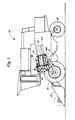
- a left side elevational view of a crop harvesting machine commonly referred to as a combine harvester, incorporating the principles of the instant invention can be seen.
- Any left and right references are used as a matter of convenience and are determined by standing at the rear of the machine and facing in the direction of operatigve travel.
- Any foreward, rearward, upper, lower etc. references equally are used as a matter of convenience and thus should be considered not to be limiting.
- the combine harvester 10 includes a wheeled frame 12 to permit movement of the combine over the ground G.
- a header 13 is supported from the frame 12 forwardly of the combine 10 to receive standing crop material from the ground G and convey it rearwardly into a feeder house structure 14 that is operable to convey a flow of crop material into the infeed area 16 of the threshing and separating rotors 15.
- the crop material is fed between the rotors 15 and the corresponding concaves 20 where rasp bar assemblies 19 thresh the crop against the concaves 20 within the threshing area 18.
- the harvesting operation of such an axial flow combine is well known in the art and is described, for example, in U.S. Patent No. 3,916,912.
- FIG. 2 The partial cross-sectional view of Fig. 2 best shows the positional relationships between the left hand threshing and separating rotor 15 and the associated concave 20.
- the concave 20 is provided with arcuate frame members 22, 23 supporting a plurality of fore-and-aft extending rub bars 24 cooperable with the rasp bar assemblies 19 mounted on the rotor 15 to separate the grain from crop material as noted above.
- the concaves 20 are mounted on a sub-frame assembly 25 that is adjustable to permit positional settings of the concaves 20 relative to the rotors 15 to provide variable spacing between the rasp bar assemblies 19 and the rub bars 24.
- a sub-frame assembly 25 that is adjustable to permit positional settings of the concaves 20 relative to the rotors 15 to provide variable spacing between the rasp bar assemblies 19 and the rub bars 24.
- the concave extensions 30 are mounted between two longitudinally spaced concave frame members 22, 23 adjacent the side sheets 27 of the combine harvester 10. Access to the concave extensions 30 can be gained through the access doors 28 on the respective side sheets 27.
- the mounting of a concave extension 30 to a forwardmost concave frame member 23 is shown in the exploded view of Fig. 3.
- the mounting of the concave extension 30 to the rearwardly spaced concave frame member 22 is substantially identical to that shown with respect to the forwardmost frame member 23 in Fig. 3. and therefore will not be described separately hereafter.
- the forwardmost concave frame member 23 is provided with a first mounting pin 32 which projects fore-and-aft of the frame member 23 for reasons to be described in greater detail below.
- the forwardmost frame member 23 also includes a second mounting pin 34 spaced radially outwardly with respect to the rotor 15 from the first mounting pin 34.
- the forwardmost frame member 23 is also provided with a number of openings 36,37,38 therethrough to be utilized as a securing means also described in greater detail below.
- Each concave extension 30 is comprised of a sub-frame assembly 40 supporting a number of longitudinally mounted rub bars 42 positioned in a parallel fashion similar to the concave rub bars 24.
- Each sub-frame assembly 40 is equipped, at both its forward and rearward ends, with a clevis 45 of a size to be engageable with a corresponding one of the mounting pins 32,34 to permit rotational movement of said sub-frame 40 relative to the corresponding concave frame members 22,23.
- Each sub-frame assembly 40 is also provided with holes 47 extending therethrough to be alignable with corresponding openings 36,37,38 in the concave frame members 22,23 when the clevis 45 are mounted on respective ones of the mounting pins 32,34 as is described with respect to Figs. 4-6 below.
- a fastener 49 is interengageable with each hole 47 and a corresponding one of the aligned openings 36,37,38 to positionally fix the extension 30 relative to the concave frame members 22,23.
- Each nut portion 49a could be in the form of a series of nuts (not shown) welded to the respective frame members 22,23 at the openings 36,37,38 if the filler plate 50 were not used.
- a filler plate 50 is mounted on the first mounting pin 32 forwardly of each forwardmost concave frame member 23 to be rotatable thereon relative to both the forwardmost concave frame member 23 and the concave extension 30.
- Each filler plate 50 is provided with a slotted hole 52 alignable with the openings 36,37 in the corresponding forwardmost frame member 23 so as to be engageable with the fastener 49 to fix the rotative position of each filler plate 50 relative to the corresonding concave extension 30 as desired.
- Each filler plate 50 is also provided with a second hole 54 therethrough to be alignable with the third opening 38 in the corresponding concave frame member 23 to positionally fix the filler plate 50 against this forwardmost frame member 23 when the concave extension 30 is in its withdrawn position as described with respect to Fig. 6 below.
- each concave extension 30 and associated filler plate 50 are best shown in Figs. 4-6.
- the thresh position of the left hand concave extension 30 is shown in Fig. 4.
- the clevis 45 are mounted on the respective corresponding first mounting pins 32 while that the holes 47 are aligned with the respective corresponding first openings 36 and locked into position by the fasteners 49 to position this concave extension 30 in close proximity to the rasp bar assemblies 19 similar to the rub bars 24 of the concave 20.
- the path of movement of the periphery of the rasp bar assemblies 19 is depicted by the arcuate line 60. In the position depicted in Fig.
- the concave extension 30 operates as an additional threshing area for the concave 20 and provides supplemental threshing action for the rotor 15.
- the filler plate 50 is locked in its uppermost position to block the front of the concave extension 30 in a similar manner as the forwardmost frame member 23 does with the rub bars 24.
- the swept position for the left hand concave extension 30 is depicted in Fig. 5.
- the clevis 45 are again mounted on the corresponding first mounting pins 32.
- the holes 47 now are aligned with the lower openings 37 to rotatably drop this concave extension 30 in a position extending almost tangentially to the path of travel 60 of the rasp bar assemblies 19.
- the filler plate 50 can be adjusted in the manner shown in phantom in Fig. 5.
- the operation of the concave extension 30 in this swept position provides partial threshing but also provides a transition mode between the concaves 20 and the rotor covers 59 which are positioned radially outwardly with respect to the rotors 15 further than the concaves 20 as can be seen in Fig. 2.
- This particular configuration has been found to reduce plugging and to provide good separation in certain crop conditions where it is advantageous for the rotors 15 to provide a sweeping action to the rub bars 42 in the concave extensions 30.
- Each concave extension 30 is also positionable in a withdrawn position as shown in Fig. 6.
- the clevis 45 are mounted on the corresponding second mounting pins 34 and the holes 47 are aligned with the corresponding third openings 38 to further drop this concave extension 30 away from the rasp bar assemblies 19.
- the filler plate 50 is positioned with the fastener 49 extending through the second hole 54 to lock this filler plate 50 in its shown rotated position which provides a transition from the infeed portion 16 of the corresponding threshing and separating rotor 15.
- the concave extensions 30 By mounting the concave extensions 30 directly to the concave frame members 22,23, the concave extensions 30 are positionally set with the concaves 20 by the support subframe25 whenever a variable setting relative to the rasp bar assemblies 19 is desired. A removal of two bolts, one each engaging the forwardmost concave frame member 23 and the rearwardly spaced frame member 22, permits a quick positioning of each concave extension to any one of the three positions described above. Access to the concave extensions 30 can be easily gained through the access doors 28 in the combine side sheets 27 to affect servicing and/or removal of the concave extensions 30.
- a concave extension in accordance with the instant invention may be provided either at only one transverse side or at both transversely opposite sides of the concave circumferentially mounted relative to the single axial flow threshing and separating rotor.
- a concave extension according to the invention may be provided at the outboard transverse side of each side-by-side extending concave.
Landscapes
- Life Sciences & Earth Sciences (AREA)
- Environmental Sciences (AREA)
- Threshing Machine Elements (AREA)
Applications Claiming Priority (2)
| Application Number | Priority Date | Filing Date | Title |
|---|---|---|---|
| US858159 | 1986-05-01 | ||
| US06/858,159 US4711075A (en) | 1986-05-01 | 1986-05-01 | Integrally mounted positionable concave extension |
Publications (2)
| Publication Number | Publication Date |
|---|---|
| EP0244007A1 true EP0244007A1 (fr) | 1987-11-04 |
| EP0244007B1 EP0244007B1 (fr) | 1992-03-18 |
Family
ID=25327633
Family Applications (1)
| Application Number | Title | Priority Date | Filing Date |
|---|---|---|---|
| EP87200676A Expired EP0244007B1 (fr) | 1986-05-01 | 1987-04-10 | Prolongement de contre-batteur monté de façon réglable |
Country Status (4)
| Country | Link |
|---|---|
| US (1) | US4711075A (fr) |
| EP (1) | EP0244007B1 (fr) |
| CA (1) | CA1288309C (fr) |
| DE (1) | DE3777439D1 (fr) |
Cited By (4)
| Publication number | Priority date | Publication date | Assignee | Title |
|---|---|---|---|---|
| EP0334957A1 (fr) * | 1987-08-25 | 1989-10-04 | Golovnoe Spetsializirovannoe Konstruktorskoe Bjuro Po Mashinam Dlya Uborski Zernovykh Kultur I Samokhodnym Shassi | Dispositif de battage d'une moissonneuse-batteuse axiale |
| AU608940B2 (en) * | 1988-01-28 | 1991-04-18 | Horwood Bagshaw Australia Limited | Improvements in thresher concaves |
| WO2001037637A1 (fr) * | 1999-11-26 | 2001-05-31 | New Holland Belgium Nv | Polyvalence amelioree de moissonneuses-batteuses a flux axial |
| US11445578B2 (en) | 2018-10-10 | 2022-09-13 | Lg Electronics Inc. | Induction heating device with improved function for distinguishing object |
Families Citing this family (25)
| Publication number | Priority date | Publication date | Assignee | Title |
|---|---|---|---|---|
| US4988326A (en) * | 1990-03-15 | 1991-01-29 | Deere & Company | Concave grid inserts |
| US5919087A (en) * | 1997-11-06 | 1999-07-06 | New Holland North America, Inc. | Concave latch mechanism for an agricultural combine |
| US6358142B1 (en) | 2000-02-14 | 2002-03-19 | Case Corporation | Concave assembly and support structure for a rotary combine |
| CA2459608C (fr) * | 2004-03-02 | 2009-02-24 | Gerald A. Foster | Contre-batteur pour moissonneuse-batteuse |
| US7166026B2 (en) * | 2004-07-22 | 2007-01-23 | Cnh America Llc | Stepped grate for an agricultural combine |
| US7393274B2 (en) * | 2006-02-01 | 2008-07-01 | Agco Corporation | Combine harvester processing system having adjustable members |
| US7473169B2 (en) * | 2007-02-28 | 2009-01-06 | Cnh America Llc | Adjustable axial rotor discharge deflector |
| US8146231B2 (en) * | 2007-05-23 | 2012-04-03 | Cnh America Llc | Insertion tool for a rotary chopper element of an integral chopper assembly of a combine harvester |
| US8133100B2 (en) * | 2009-12-18 | 2012-03-13 | Agco Corporation | Combine harvester processing system having adjustable concaves on a suspension system |
| US8133101B2 (en) * | 2009-12-18 | 2012-03-13 | Agco Corporation | Concave adjustment mechanism |
| US8628390B2 (en) * | 2011-04-19 | 2014-01-14 | Cnh America Llc | Support system for separator grates of a harvester |
| US8926415B2 (en) | 2012-01-11 | 2015-01-06 | Cnh Industrial America Llc | Depth adjustable crop transport vane |
| BE1021166B1 (nl) * | 2013-11-20 | 2016-01-29 | Cnh Industrial Belgium Nv | Dorskorfsysteem en werkwijze voor oogstmachine |
| US9723791B1 (en) | 2014-03-05 | 2017-08-08 | Kevin J. Kile | Concaves for an agricultural combine |
| US10440893B2 (en) | 2014-03-05 | 2019-10-15 | Kevin J. Kile | Concaves for an agricultural combine |
| US9504204B2 (en) | 2014-03-05 | 2016-11-29 | Kevin J. Kile | Removable concave threshing bars for an agricultural combine |
| DE102014114717A1 (de) * | 2014-10-10 | 2016-04-14 | Hartmut Kemmner | Vorrichtung zum Bearbeiten von Erntegut und Verfahren zum Steuern eines Erntegutflusses in der Vorrichtung |
| DE102015205992A1 (de) * | 2015-04-02 | 2016-10-06 | Deere & Company | Dresch- oder Separierkorb mit wenigstens einem demontierbaren Einsatz |
| BR102016008710B1 (pt) * | 2015-05-29 | 2021-06-15 | Cnh Industrial Belgium Nv | Colheitadeira agrícola e método para carregar um côncavo em um conjunto de armação |
| US10932414B2 (en) * | 2017-11-29 | 2021-03-02 | Agco Corporation | Concave adjustment system in a combine harvester twin axial-flow crop processor |
| WO2019199889A1 (fr) * | 2018-04-12 | 2019-10-17 | Cnh Industrial America Llc | Rampe concave pour véhicule agricole |
| US10993375B2 (en) * | 2018-06-19 | 2021-05-04 | Ecomill, Llc | Centrifugal scattering device |
| US10639645B2 (en) | 2018-06-19 | 2020-05-05 | Ecomill, Llc | Method for separating fine fractures and coarse fractures using a vacuum |
| US20200296895A1 (en) * | 2019-03-21 | 2020-09-24 | Cnh Industrial America Llc | Removable insert for a threshing rotor cage |
| DE102021128494A1 (de) * | 2021-11-02 | 2023-05-04 | Deere & Company | Dreschkorb für einen Mähdrescher |
Citations (10)
| Publication number | Priority date | Publication date | Assignee | Title |
|---|---|---|---|---|
| FR676217A (fr) * | 1928-06-06 | 1930-02-20 | Batteuse axiale | |
| FR793982A (fr) * | 1934-06-09 | 1936-02-05 | Schlayer Heliaks | Machine à battre axiale |
| FR847078A (fr) * | 1938-06-07 | 1939-10-03 | Perfectionnements apportés aux contre-batteurs de machines à battre les céréales, etc. | |
| FR1074372A (fr) * | 1953-04-08 | 1954-10-05 | Perfectionnement aux machines à battre les céréales ou matières analogues | |
| DE1130641B (de) * | 1960-09-27 | 1962-05-30 | Dipl Wirtschafts Ing Reinhold | Dreschkorb fuer die Drescheinrichtung einer Dreschmaschine, insbesondere eines Maehdreschers |
| GB997650A (en) * | 1963-06-13 | 1965-07-07 | Deere & Co | Beater grate attachment for threshing and separating mechanism |
| FR1479557A (fr) * | 1966-03-25 | 1967-05-05 | Garnier & Cie J | Perfectionnement aux batteuses, moissonneuses-batteuses et machines analogues |
| AU1236370A (en) * | 1970-03-09 | 1971-09-16 | EDWARD SMITH and MERVYN KEITH DAY MALCOLM | Grain separator |
| US4004404A (en) * | 1976-03-01 | 1977-01-25 | Sperry Rand Corporation | Rotary combine with improved concave |
| EP0085358A1 (fr) * | 1982-01-29 | 1983-08-10 | Klöckner-Humboldt-Deutz Aktiengesellschaft | Moissonneuse-batteuse à dispositif de battage à écoulement axial |
Family Cites Families (7)
| Publication number | Priority date | Publication date | Assignee | Title |
|---|---|---|---|---|
| US792986A (en) * | 1904-11-05 | 1905-06-20 | James P Henderson | Threshing-machine. |
| CH214559A (de) * | 1939-06-26 | 1941-05-15 | Heinrich Lanz Ag | Dreschkorb an Dreschmaschinen. |
| US3696815A (en) * | 1971-12-20 | 1972-10-10 | Sperry Rand Corp | Detachable side plate for a threshing and separating unit of an axial flow combine |
| US4031901A (en) * | 1976-06-07 | 1977-06-28 | Sperry Rand Corporation | Concave for an axial flow type combine |
| US4078571A (en) * | 1976-07-14 | 1978-03-14 | Sperry Rand Corporation | Separating unit for combine harvesters |
| US4249543A (en) * | 1979-11-02 | 1981-02-10 | Sperry Corporation | Rotor access module |
| EP0092599B1 (fr) * | 1982-04-28 | 1988-07-13 | Deere & Company | Dispositif pour régler l'écartement entre le batteur et le contre-batteur d'une moissonneuse-batteuse |
-
1986
- 1986-05-01 US US06/858,159 patent/US4711075A/en not_active Expired - Lifetime
-
1987
- 1987-03-18 CA CA000532378A patent/CA1288309C/fr not_active Expired - Lifetime
- 1987-04-10 DE DE8787200676T patent/DE3777439D1/de not_active Expired - Lifetime
- 1987-04-10 EP EP87200676A patent/EP0244007B1/fr not_active Expired
Patent Citations (10)
| Publication number | Priority date | Publication date | Assignee | Title |
|---|---|---|---|---|
| FR676217A (fr) * | 1928-06-06 | 1930-02-20 | Batteuse axiale | |
| FR793982A (fr) * | 1934-06-09 | 1936-02-05 | Schlayer Heliaks | Machine à battre axiale |
| FR847078A (fr) * | 1938-06-07 | 1939-10-03 | Perfectionnements apportés aux contre-batteurs de machines à battre les céréales, etc. | |
| FR1074372A (fr) * | 1953-04-08 | 1954-10-05 | Perfectionnement aux machines à battre les céréales ou matières analogues | |
| DE1130641B (de) * | 1960-09-27 | 1962-05-30 | Dipl Wirtschafts Ing Reinhold | Dreschkorb fuer die Drescheinrichtung einer Dreschmaschine, insbesondere eines Maehdreschers |
| GB997650A (en) * | 1963-06-13 | 1965-07-07 | Deere & Co | Beater grate attachment for threshing and separating mechanism |
| FR1479557A (fr) * | 1966-03-25 | 1967-05-05 | Garnier & Cie J | Perfectionnement aux batteuses, moissonneuses-batteuses et machines analogues |
| AU1236370A (en) * | 1970-03-09 | 1971-09-16 | EDWARD SMITH and MERVYN KEITH DAY MALCOLM | Grain separator |
| US4004404A (en) * | 1976-03-01 | 1977-01-25 | Sperry Rand Corporation | Rotary combine with improved concave |
| EP0085358A1 (fr) * | 1982-01-29 | 1983-08-10 | Klöckner-Humboldt-Deutz Aktiengesellschaft | Moissonneuse-batteuse à dispositif de battage à écoulement axial |
Cited By (6)
| Publication number | Priority date | Publication date | Assignee | Title |
|---|---|---|---|---|
| EP0334957A1 (fr) * | 1987-08-25 | 1989-10-04 | Golovnoe Spetsializirovannoe Konstruktorskoe Bjuro Po Mashinam Dlya Uborski Zernovykh Kultur I Samokhodnym Shassi | Dispositif de battage d'une moissonneuse-batteuse axiale |
| EP0334957A4 (fr) * | 1987-08-25 | 1990-06-26 | Gol Spk Bjuro Mashinam Dlya Ub | Dispositif de battage d'une moissonneuse-batteuse axiale. |
| AU608940B2 (en) * | 1988-01-28 | 1991-04-18 | Horwood Bagshaw Australia Limited | Improvements in thresher concaves |
| WO2001037637A1 (fr) * | 1999-11-26 | 2001-05-31 | New Holland Belgium Nv | Polyvalence amelioree de moissonneuses-batteuses a flux axial |
| US6485364B1 (en) * | 1999-11-26 | 2002-11-26 | New Holland North America, Inc. | Removable concaves for axial flow combines |
| US11445578B2 (en) | 2018-10-10 | 2022-09-13 | Lg Electronics Inc. | Induction heating device with improved function for distinguishing object |
Also Published As
| Publication number | Publication date |
|---|---|
| DE3777439D1 (de) | 1992-04-23 |
| CA1288309C (fr) | 1991-09-03 |
| EP0244007B1 (fr) | 1992-03-18 |
| US4711075A (en) | 1987-12-08 |
Similar Documents
| Publication | Publication Date | Title |
|---|---|---|
| EP0244007A1 (fr) | Prolongement de contre-batteur monté de façon réglable | |
| EP0241981B1 (fr) | Méthode et appareil pour le montage de contre-batteurs | |
| US3696815A (en) | Detachable side plate for a threshing and separating unit of an axial flow combine | |
| CA2521892C (fr) | Rotor pour broyeur de paille | |
| EP3627985B1 (fr) | Système d'ajustement de grilles en doigt d'une moissonneuse agricole | |
| EP1964464B1 (fr) | Ajustement de conduit d'aube pour récolte de moissonneuse-batteuse | |
| US3664100A (en) | Axial combine with rotor and concave convertible to support different threshing elements | |
| EP0250654A1 (fr) | Moissonneuse-batteuse | |
| US9894837B2 (en) | Adjustable windrow assembly for an agricultural vehicle | |
| US7059961B2 (en) | Apparatus and method for effecting movement and clearance spacing of a concave | |
| US3631862A (en) | Supporting and adjusting means for agricultural machines such as combine harvesters | |
| US4407110A (en) | Frame for crop harvesting header | |
| GB2025205A (en) | Cutterhead assembly for a forage harvester | |
| GB1568829A (en) | Axial flow combines | |
| EP3503706B1 (fr) | Unité de rang de moissonneuse agricole | |
| BR102016009856A2 (pt) | System and adjustment method of agricultural harvest | |
| US3994304A (en) | Back-flow retarding feed plate for rotary combine | |
| GB2061686A (en) | Combine harvesters | |
| US4628946A (en) | Harvesting machine including chopper means | |
| GB2099676A (en) | Combine harvesters | |
| US11712002B2 (en) | Residue spreader for a combine harvester | |
| JP2009219443A (ja) | 全稈投入型脱穀機 | |
| CA1088837A (fr) | Moissonneuse - batteuse comportant un rabatteur decale par rapport a l'axe longitudinal | |
| CA1094903A (fr) | Grille de battage pour moissonneuse-batteuse | |
| CA1086595A (fr) | Dispositif de reglage du mecanisme de distribution d'une moisonneuse-batteuse du type a ecoulement axial |
Legal Events
| Date | Code | Title | Description |
|---|---|---|---|
| PUAI | Public reference made under article 153(3) epc to a published international application that has entered the european phase |
Free format text: ORIGINAL CODE: 0009012 |
|
| 17P | Request for examination filed |
Effective date: 19870410 |
|
| AK | Designated contracting states |
Kind code of ref document: A1 Designated state(s): DE FR GB |
|
| RAP1 | Party data changed (applicant data changed or rights of an application transferred) |
Owner name: FORD NEW HOLLAND, INC. (A DELAWARE CORP.) |
|
| 17Q | First examination report despatched |
Effective date: 19891229 |
|
| ITF | It: translation for a ep patent filed |
Owner name: MODIANO & ASSOCIATI S.R.L. |
|
| GRAA | (expected) grant |
Free format text: ORIGINAL CODE: 0009210 |
|
| AK | Designated contracting states |
Kind code of ref document: B1 Designated state(s): DE FR GB |
|
| REF | Corresponds to: |
Ref document number: 3777439 Country of ref document: DE Date of ref document: 19920423 |
|
| ET | Fr: translation filed | ||
| PLBE | No opposition filed within time limit |
Free format text: ORIGINAL CODE: 0009261 |
|
| STAA | Information on the status of an ep patent application or granted ep patent |
Free format text: STATUS: NO OPPOSITION FILED WITHIN TIME LIMIT |
|
| 26N | No opposition filed | ||
| REG | Reference to a national code |
Ref country code: GB Ref legal event code: IF02 |
|
| REG | Reference to a national code |
Ref country code: GB Ref legal event code: 732E |
|
| REG | Reference to a national code |
Ref country code: FR Ref legal event code: TP Ref country code: FR Ref legal event code: CD |
|
| PGFP | Annual fee paid to national office [announced via postgrant information from national office to epo] |
Ref country code: GB Payment date: 20060330 Year of fee payment: 20 |
|
| PGFP | Annual fee paid to national office [announced via postgrant information from national office to epo] |
Ref country code: FR Payment date: 20060404 Year of fee payment: 20 |
|
| PGFP | Annual fee paid to national office [announced via postgrant information from national office to epo] |
Ref country code: DE Payment date: 20060520 Year of fee payment: 20 |
|
| REG | Reference to a national code |
Ref country code: GB Ref legal event code: PE20 |
|
| PG25 | Lapsed in a contracting state [announced via postgrant information from national office to epo] |
Ref country code: GB Free format text: LAPSE BECAUSE OF EXPIRATION OF PROTECTION Effective date: 20070409 |