EP0241981B1 - Méthode et appareil pour le montage de contre-batteurs - Google Patents
Méthode et appareil pour le montage de contre-batteurs Download PDFInfo
- Publication number
- EP0241981B1 EP0241981B1 EP87200624A EP87200624A EP0241981B1 EP 0241981 B1 EP0241981 B1 EP 0241981B1 EP 87200624 A EP87200624 A EP 87200624A EP 87200624 A EP87200624 A EP 87200624A EP 0241981 B1 EP0241981 B1 EP 0241981B1
- Authority
- EP
- European Patent Office
- Prior art keywords
- concave
- mounting
- frame
- mounting frame
- members
- Prior art date
- Legal status (The legal status is an assumption and is not a legal conclusion. Google has not performed a legal analysis and makes no representation as to the accuracy of the status listed.)
- Expired
Links
- 238000000034 method Methods 0.000 title claims description 13
- 230000000694 effects Effects 0.000 claims description 3
- 241001124569 Lycaenidae Species 0.000 claims description 2
- 230000000284 resting effect Effects 0.000 claims 1
- 238000009434 installation Methods 0.000 description 4
- 230000000712 assembly Effects 0.000 description 3
- 238000000429 assembly Methods 0.000 description 3
- 235000019994 cava Nutrition 0.000 description 3
- 238000003306 harvesting Methods 0.000 description 3
- 238000010276 construction Methods 0.000 description 1
- 230000008878 coupling Effects 0.000 description 1
- 238000010168 coupling process Methods 0.000 description 1
- 238000005859 coupling reaction Methods 0.000 description 1
- 238000012423 maintenance Methods 0.000 description 1
- 238000004519 manufacturing process Methods 0.000 description 1
Images


Classifications
-
- A—HUMAN NECESSITIES
- A01—AGRICULTURE; FORESTRY; ANIMAL HUSBANDRY; HUNTING; TRAPPING; FISHING
- A01F—PROCESSING OF HARVESTED PRODUCE; HAY OR STRAW PRESSES; DEVICES FOR STORING AGRICULTURAL OR HORTICULTURAL PRODUCE
- A01F12/00—Parts or details of threshing apparatus
- A01F12/18—Threshing devices
- A01F12/28—Devices for adjusting the concaves
-
- A—HUMAN NECESSITIES
- A01—AGRICULTURE; FORESTRY; ANIMAL HUSBANDRY; HUNTING; TRAPPING; FISHING
- A01F—PROCESSING OF HARVESTED PRODUCE; HAY OR STRAW PRESSES; DEVICES FOR STORING AGRICULTURAL OR HORTICULTURAL PRODUCE
- A01F7/00—Threshing apparatus
- A01F7/02—Threshing apparatus with rotating tools
- A01F7/06—Threshing apparatus with rotating tools with axles in line with the feeding direction ; Axial threshing machines
Definitions
- the present invention relates generally to axial flow combines and, particularly, to an improved method and apparatus for mounting a concave on a mounting frame for selective positioning relative to the threshing and separating rotor.
- the feeder and feed plate must be removed from the combine before the concave front supports can be unbolted and then the concaves removed through the front of the combine.
- the installation of the concaves involves a reversal of this procedure.
- an axial flow combine harvester which comprises :
- the concave comprises a pair of transversely extending, longitudinally spaced apart concave frame members.
- a pair of cooperating mounting members is associated with each on of said concave frame members.
- Each pair of cooperating mounting members preferably is in the form of a cooperating mounting pin and yoke; the pin being affixed to either one of both the mounting frame and the concave and the yoke being provided on the other one of both said mounting frame and concave and further being positioned such that engagement thereof with the corresponding mounting pin can be effected by moving the concave in the transverse direction.
- the mounting pins are affixed to the mounting frame and the yokes are connected to the concave frame members.
- Retaining links preferably also are mounted on the mounting pins in conjunction with the concave yokes and are connected to the concave frame members to retain the concave on the mounting pins during operation of the combine.
- Support plates carried by the mounting frame can be utilized to support the weight of the concave during the mounting procedure.
- a method of installing a concave on an axial flow combine harvester comprising the steps of :
- a side mount concave mounting apparatus for use in an axial flow combine utilizing a longitudinally extending threshing and separating rotor is provided and which greatly reduces the time and work required to remove and/or install the concave to the extent that the feeder and feed plate do not need to be removed from the combine in order to remove and/or install said concave.
- This concave mounting apparatus is durable in construction, inexpensive of manufacture, carefree of maintenance, facile in assemblage and simple and effective in use.
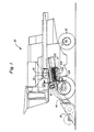
- Fig. 1 is a left side elevational view of a combine harvester incorporating the principles of the instant invention, a portion of the side sheet of the combine being broken away to more clearly show the relative positions of the threshing and separating rotors and cooperatively mounted concaves;
- Fig. 2 is an enlarged partial cross-sectional view taken along lines 2-2 of Fig.
- Fig. 3 is an enlarged exploded view of the forwardmost portion of the left hand concave identifying the manner in which the concave and retaining link are mounted on the adjustable mounting frame.
- a left side elevational view of a crop harvesting machine commonly referred to as an axial flow combine harvester, incorporating the principles of the instant invention, can be seen.
- Any left and right references are used as a matter of convenience and are determined by standing at the rear of the machine and facing in the direction of operative travel.
- the combine 10 is mounted on a wheeled frame 12 to mobilely support the combine 10 over the ground G for the harvesting of crops therefrom.
- a header 13 is mounted on the forward periphery of the combine 10 to engage and gather crop material from the ground G and consolidate it into a feederhouse structure 14.
- the feederhouse 14 conveys a flow of crop material into the infeed area 16 of the threshing and separating rotors 15.
- the concave 20 is provided with at least two longitudinally spaced frame members 22,23, the forwardmost one of which is designated by the reference numeral 23 and which carry a plurality of longitudinally extending rub bars 24 radially positioned relative to the rotor 15. Crop material entering between the rotor 15 and the concave 20 is rubbed between the rasp bar assemblies 18 and the rub bars 24 to separate grain from the crop material.
- the concave 20 is mounted on an adjustable mounting frame 25 to permit adjustment of the concave 20 relative to the rotor 15 as is described in greater detail in U.S. Patent No. 4, 375,221, the description of which is incorporated herein by reference.
- Figs. 2 and 3 the structure of the instant invention can best be seen and will be described hereinafter with reference to the left hand concave; the structure and operation of the right hand concave being identical thereto.
- the forwardmost concave frame member 23 is shown in Fig. 3
- the rearwardmost concave frame member 22 is constructed in a similar manner and the description given below with respect to the forwardmost frame member 23 is equally applicable to the structure and operation of this rearwardmost concave frame member 22.
- the description given below with respect to the left hand concave equally applies to the right hand concave.
- each concave 20 is provided with a clevis mechanism 27 in the form of open yokes 28 affixed to the frame member 22,23 in a permanent fashion.
- Each yoke 28 is engageable with a mounting pin 29 projecting in a longitudinal direction from the mounting frame 25 and is oriented in such a manner as to be engageable with said mounting pin 29 when the concave 20 is moved in a transverse direction toward the mounting pins 29.
- a retaining link 30 is also mountable on each mounting pin 29 and connectable to the corresponding concave frame member 22,23 by fasteners 32 in a manner such that these retaining links 30 are selectively disconnectable from the corresponding frame members 22 , 23.
- two transversely spaced apart fasteners are utilized for coupling each retaining link 30 to the corresponding frame member 22, 23 to guarantee a secure engagement between the corresponding pins 29 and yokes 28.
- These spaced apart fasteners preferably are positioned proximate to the outboard ends of the retaining links 30 and concave frame members 22, 23 to facilitate access thereto through the respective access openings 42 in the combine side sheets 43.
- An adjustable connecting link 35 interconnecting the mounting frame 25 and an outboard portion of each one of the frame members 22 , 23 by fasteners 36 controls the rotative position of the concave 20 about the mounting pins 29. It can be seen that an adjustment of the length of the connecting links 35 will affect a rotation of the yokes 28 about the mounting pins 29 on which they are mounted, thereby changing the relative position of the concave 20 with respect to the corresponding rotor 15 in a manner separate from the adjustment of the mounting frame 25.
- the mounting frame 25 is provided with plate members 40 positioned beneath the location of the respective concave frame members 22,23 to carry the weight of the concave 20 during the installation of the concave 20 as will be described in greater detail below.
- the plate members 40 do not support the weight of the concave 20 after the concave 20 has been mounted on the mounting frame 25; the respective concave frame members 22,23 being spaced above the corresponding plate members 40 to permit a rotative movement thereof about the mounting of the yokes 28 on the mounting pins 29 through an adjustment of the connecting links 35.
- the method of installing the side mount con caves 20 is described below with particular reference being made to Figs. 2 and 3.
- the retaining links 30 are first mounted on the mounting pins 29 by positioning the retaining links 30 such that the mounting pins 29 are inserted through the corresponding bores 31.
- the concave 20 is then inserted through the access opening 42 and, using the plates 40 to temporarily support the weight of the concave 20, the frame members 22,23 are positioned so that the yokes 28 can be guided onto the mounting pins 29.
- the fasteners 32 are then inserted through the respective frame members 22,23 and the corresponding retaining links 30 to fix the retaining links 30 to the concave frame members 22,23.
- the adjustable connecting links 35 are then connected to the respective concave frame members 22 , 23 by the fasteners 36. Any fine adjustments required of the concave 20 to position it relative to the corresponding threshing and separating rotor 15 can be obtained by adjusting the relative lengths of the connecting links 35. As seen in Fig. 2, once the concave 20 is supported on the mounting pins 29 and the connecting links 35, the respective frame members 22 , 23 are lifted off the plate members 40.
- the purpose of the retaining links 30 is to resist forces imposed on the con caves 20 to prevent the yokes 28 from becoming disengaged from the mounting pins 29 during normal harvesting operation of the combine 10.
- the retaining links 30 can be unbolted from the con cave frame members 22,23 to permit an easy removal of the con caves 20 through the transversely positioned openings 42 in the side sheets 43 of the combine 10.
- This structure eliminates the need to remove the infeed mechanism 19 located forwardly of the threshing concaves 20 in order to remove, respecively install said concaves 20. Removal of the concaves 20, such as needed for changing the concaves 20, can be accomplished in the reverse manner indicated above for installation of the concaves 20.
- the connecting links 35 can be disconnected from the concave frame members 22,23 and the concaves 20 rested upon the plate members 40.
- a disconnection of the retaining links 30 from the frame members 22,23 will permit the yokes 28 to be disengaged from the mounting pins 29 and the concaves 20 to be removed through the openings 42 in the side sheets 43.
- the pins 29 may be provided on the concave frame members 22, 23 rather than on the mounting frame 25.
- the yokes 28 obviously should be affixed to the mounting frame 25.
- the retaining links 30 still can be pivotally mounted on the mounting frame 25, preferably generally co-axially with the pins 29 when the concave 20 is mounted on this mounting frame 25.
- the retaining links can be detachably connectable to the respective concave frame members 22, 23 by fasteners 32.
- the retaining links 30 also may be pivotally mounted on the mounting pins 29 on the concave frame members 22, 23 and be detachably connectable by fastener means 32 to the mounting frame 25.
- the invention has been described hereabove in connection with a twin rotor axial flow combine. However, it will be clear that this invention equally well is applicable on a single rotor axial flow combine.
Landscapes
- Life Sciences & Earth Sciences (AREA)
- Environmental Sciences (AREA)
- Threshing Machine Elements (AREA)
Claims (17)
- Moissonneuse-batteuse à écoulement axial (10) comportant :- deux tôles latérales (43) espacées transversalement, dont l'une au moins comprend un orifice d'accès (42);- au moins un rotor de battage et de séparation (15) s'étendant dans une direction sensiblement longitudinale entre les tôles latérales (43) ;- un contre-batteur (20) positionné à la périphérie par rapport audit rotor (15) ; et- un châssis de montage (25) supportant le contre-batteur (20) par rapport au rotor (15) correspondant ; le contre-batteur (20) étant monté de façon amovible sur le châssis de montage (25) à l'aide de moyens de montage (28, 29, 35) positionnés sensiblement au niveau des côtés longitudinaux opposés transversalement dudit contre-batteur (20) et les moyens de montage (28, 29), prévus sensiblement au niveau du côté longitudinal du contre-batteur (20) orienté à l'opposé de l'orifice d'accès (42) ménagé dans ladite tôle latérale (43), étant formés par des organes coopérants prévus à la fois sur le contre-batteur (20) et sur le châssis de montage (25), et qui est
caractérisée en ce que :
les éléments de montage coopérants (28, 29) prévus sensiblement au niveau du côté longitudinal du contre-batteur (20) orienté à l'opposé dudit orifice d'accès (42) permettent un accouplement avec le contrebatteur sensiblement suivant une direction transversale, moyennant quoi le contre-batteur (20) peut être monté sur le châssis de montage (25) dans une direction transversale par ledit orifice d'accès (42). - Moissonneuse-batteuse selon la revendication 1, caractérisée en ce que le contre-batteur (20) comporte deux éléments de châssis de contre-batteur (22, 23) s'étendant transversalement et espacés longitudinalement; deux éléments de montage coopérants (28, 29) étant associés à chacun desdits éléments de châssis de contre-batteur (22, 23).
- Moissonneuse-batteuse selon la revendication 2, caractérisée en ce que les deux éléments de montage coopérants (28, 29) ont de préférence la forme d'une broche (29) et d'un étrier (28) coopérants ; la broche (29) étant fixée au châssis de montage (25) ou au contre-batteur (20) et l'étrier (28) étant prévu respectivement sur le contre-batteur (20) ou sur le châssis de montage (25) et étant en outre positionné de telle sorte qu'on puisse l'accoupler avec la broche de montage correspondante (29) en déplaçant le contre-batteur (20) dans le sens transversal.
- Moissonneuse-batteuse selon la revendication 3, caractérisée en ce qu'au moins un moyen formant tringlerie de retenue (30) est apte à être intercalé de façon amovible entre le châssis de montage (25) et le contre-batteur (20) pour maintenir en position les étriers (28) sur les broches de montage respectives (29) pendant le fonctionnement des moissonneuses-batteuses (10).
- Moissonneuse-batteuse selon la revendication 4, caractérisée en ce qu'un moyen formant tringlerie de retenue (30) est associé à chaque broche (29) et étrier (28) coopérants.
- Moissonneuse-batteuse selon la revendication 5, caractérisée en ce que chaque moyen formant tringlerie de retenue (30) a la forme d'une tringle qui est apte à être montée pivotante sur le châssis de montage (25) ou sur un élément de châssis de contre-batteur (22, 23) correspondant en un point sensiblement dans l'alignement de la broche de montage (29) correspondante, et qui est apte à être reliée de façon amovible respectivement à l'élément de châssis de contre-batteur (22, 23) correspondant ou au châssis de montage (25) en un point éloigné de la Croche (29) et de l'étrier (28) coopérants correspondants.
- Moissonneuse-batteuse selon la revendication 6, caractérisée en ce que chaque tringle de retenue (30) est apte à être reliée de façon amovible audit élément de châssis de contre-batteur correspondant (22, 23), respectivement au châssis de montage (25) à l'aide d'au moins deux attaches (32) en des points espacés sur la longueur de ladite tringle (30) et à une certaine distance de la broche (29) et de l'étrier (28) coopérants correspondants.
- Moissonneuse-batteuse selon l'une quelconque des revendications précédentes, caractérisée en ce que les moyens de montage (35) prévus entre le châssis de montage (25) et le contre-batteur (20) et positionnés sensiblement au niveau du côté longitudinal du contrebatteur (20) voisin de l'une des tôles latérales (43) comprenant l'orifice d'accès (42) ont la forme de tringles de liaison (35) reliant entre eux de façon amovible ledit contre-batteur (20) et ledit châssis de montage (25) pour fixer la position du contre-batteur (20) par rapport au châssis de montage (25).
- Moissonneuse-batteuse selon la revendication 8, caractérisée en ce que les tringles de liaison (35) sont réglables pour varier en longueur et provoquer un mouvement rotatif du contre-batteur (20) autour d'un axe des éléments de montage coopérants (28, 29) en vue de régler la position du contre-batteur (20) par rapport au rotor (15).
- Moissonneuse-batteuse selon l'une quelconque des revendications précédentes, caractérisée en ce que le châssis de montage (25) comprend des moyens forment surfaces de support (40) voisins du contre-batteur (20) pour supporter temporairement celui-ci pendant son mouvement transversal destiné à réaliser l'accouplement entre les éléments de montage coopérants (28, 29) sensiblement au niveau du côté longitudinal du contre-batteur (20) orienté à l'opposé dudit orifice d'accès (42).
- Moissonneuse-batteuse selon la revendication 10 lorsqu'elle est dépendante directement ou indirectement de la revendication 2, caractérisée en ce que les moyens formant surfaces de support (40) ont la forme de deux éléments formant plaques (40) fixés au châssis de montage (25) au-dessous des éléments de châssis de contre-batteur (22, 23).
- Moissonneuse-batteuse selon l'une quelconque des revendications précédentes, caractérisée en ce qu'elle est du type à écoulement axial à rotor double et comporte un châssis de montage simple (25) adapté en vue de supporter deux contre-batteurs (20) s' étendant côte-à-côte, par rapport à des rotors de battage et de séparation (15) respectifs ; chaque contre-batteur (20) étant apte à être monté sur le châssis de montage (25) dans une direction transversale par un orifice d'accès (42) ménagé dans la tôle latérale de moissonneuse-batteuse (43) adjacente, et des éléments de montage (28, 29) aptes à coopérer étant associés aux deux contre-batteurs (20) sensiblement au niveau des côtés longitudinaux opposés de celui-ci ; lesdits éléments de montage coopérants (28, 29) permettant leur accouplement mutuel lorsque les contre-batteurs (20) sont déplacés dans lesdites directions transversales.
- Méthode d'installation d'un contre-batteur (20) sur une moissonneuse-batteuse à écoulement axial (10) ; ledit contre-batteur (20) étant apte à être monté sur un châssis de montage (25) prévu à l'intérieur de la moissonneuse-batteuse (10) et portant des premiers moyens de montage (29) aptes à coopérer avec des seconds moyens de montage (29) prévus sur le contre-batteur (20) pour supporter celui-ci dans un rapport de coopération avec un rotor de battage et de séparation (15) ; la méthode étant caractérisée en ce qu'elle comporte les étapes consistant à :- introduire le contre-batteur (20) par un orifice (42) ménagé dans une tôle latérale (43) de la moissonneuse-batteuse (10) ; ledit orifice (42) étant apte à être fermé par une porte (45) ;- déplacer le contre-batteur (20) dans une direction transversale vers les premiers moyens de montage (29) pour réaliser l'accouplement entre les premiers et les seconds moyens de montage (28,29) ; lesdits seconds moyens de montage (28) étant mobiles en rotation par rapport aux premiers moyens de montage (29) lorsqu' ils sont accouplés, afin de permettre un mouvement du contre-batteur (20) par rapport au rotor (15) ;- fixer au moins une tringle de retenue (30) entre le châssis de montage (25) et le contre-batteur (20) pour empêcher un désaccouplement des seconds (28) et des premiers (29) moyens de montage pendant le fonctionnement de la moissonneuse-batteuse (10) ; et- intercaler au moins une tringle de liaison (35) entre le châssis de montage (25) et le contre-batteur (20) à un emplacement éloigné des premiers et seconds moyens de montage coopérants (29, 28) pour supporter le contre-batteur (20) sur le châssis de montage (25) et commander la position angulaire du contre-batteur (20) par rapport au rotor (15).
- Méthode selon la revendication 13, caractérisée en ce que:- l'étape de déplacement comprend l'accouplement de deux seconds éléments de montage (28) espacés longitudinalement prévus sur les éléments de châssis respectifs (22, 23) du contre-batteur (20) avec les deux premiers éléments de montage (29) correspondants, également espacés longitudinalement, prévus sur ledit châssis de montage (25) ; lesdits deux premiers et seconds éléments de montage (29, 28) formant respectivement lesdits premiers et seconds moyens de montage (29, 28) ;- l'étape de fixation comprend la fixation d'une tringle de retenue (30) entre chacun desdits éléments de châssis de contre-batteur (22, 23) et le châssis de montage (25) ; et- l'étape de liaison comprend l'interconnexion d'une tringle de liaison (35) entre ledit élément de châssis de contre-batteur (22, 23) et le châssis de montage (25) en un point éloigné des deux premiers et seconds éléments de montage coopérants (29, 28) associés à chaque élément de châssis de contre-batteur (22, 23) respectif.
- Méthode selon la revendication 13 ou 14, caractérisée en ce que l'étape de déplacement comprend l'étape consistant à poser le contrebatteur (20) sur des moyens formant surfaces de support (40) positionnés sur le châssis de montage (25) en vue de supporter une partie du poids du contre-batteur (20) pendant ladite étape de déplacement.
- Méthode selon la revendication 15, caractérisée en ce que l'étape de liaison comprend :- l'étape consistant à relever le contre-batteur (20) audessus des moyens formant surfaces de support (40) ; et- l'étape consistant à sélectionner la longueur de la ou de chaque tringle de liaison (35) pour sélectionner une position de rotation souhaitée du contre-batteur (20) autour des premiers moyens de montage (29) prévus sur le châssis de montage (25) et positionner ainsi sélectivement le contre-batteur (20) par rapport au rotor (15).
- Méthode selon l'une quelconque des revendications 14 à 16, caractérisée en ce que l'étape de fixation comprend les étapes consistant à :- monter une tringle de retenue (30) sur chaque premier élément de montage respectif ayant la forme d'une broche de montage (29) s'étendant longitudinalement et fixée au châssis de montage (25) ; lesdites tringles de retenue (30) étant aptes à être positionnées sur lesdites broches de montage (29) le long de l'axe de celles-ci seulement; et- rattacher lesdites tringles de retenue (30) auxdits éléments de châssis de contre-batteur (22, 23) correspondants.
Applications Claiming Priority (2)
| Application Number | Priority Date | Filing Date | Title |
|---|---|---|---|
| US848507 | 1986-04-07 | ||
| US06/848,507 US4711252A (en) | 1986-04-07 | 1986-04-07 | Method and apparatus for mounting concaves |
Publications (2)
| Publication Number | Publication Date |
|---|---|
| EP0241981A1 EP0241981A1 (fr) | 1987-10-21 |
| EP0241981B1 true EP0241981B1 (fr) | 1991-05-08 |
Family
ID=25303468
Family Applications (1)
| Application Number | Title | Priority Date | Filing Date |
|---|---|---|---|
| EP87200624A Expired EP0241981B1 (fr) | 1986-04-07 | 1987-04-03 | Méthode et appareil pour le montage de contre-batteurs |
Country Status (4)
| Country | Link |
|---|---|
| US (1) | US4711252A (fr) |
| EP (1) | EP0241981B1 (fr) |
| CA (1) | CA1272095A (fr) |
| DE (1) | DE3769828D1 (fr) |
Families Citing this family (27)
| Publication number | Priority date | Publication date | Assignee | Title |
|---|---|---|---|---|
| US4988326A (en) * | 1990-03-15 | 1991-01-29 | Deere & Company | Concave grid inserts |
| US5919087A (en) * | 1997-11-06 | 1999-07-06 | New Holland North America, Inc. | Concave latch mechanism for an agricultural combine |
| GB2356546A (en) * | 1999-11-26 | 2001-05-30 | Ford New Holland Nv | Threshing and separating unit for axial flow combines |
| US6358142B1 (en) * | 2000-02-14 | 2002-03-19 | Case Corporation | Concave assembly and support structure for a rotary combine |
| GB2385505A (en) * | 2002-02-22 | 2003-08-27 | Ford New Holland Nv | Tool and method for removal and installation of threshing concaves |
| US7001268B2 (en) * | 2003-07-17 | 2006-02-21 | Deere & Company | Latch mechanism for a grate in an agricultural combine |
| ATE352194T1 (de) * | 2004-03-12 | 2007-02-15 | Deere & Co | Gewächsbearbeitungsvorrichtung |
| US20060287020A1 (en) * | 2005-06-15 | 2006-12-21 | Blaine Muhr | Concave lifting device |
| US7393274B2 (en) * | 2006-02-01 | 2008-07-01 | Agco Corporation | Combine harvester processing system having adjustable members |
| US8092286B2 (en) * | 2007-05-23 | 2012-01-10 | Cnh America Llc | Concave pan portion of an integral chopper assembly of a combine harvester |
| US8133101B2 (en) * | 2009-12-18 | 2012-03-13 | Agco Corporation | Concave adjustment mechanism |
| US8133100B2 (en) * | 2009-12-18 | 2012-03-13 | Agco Corporation | Combine harvester processing system having adjustable concaves on a suspension system |
| US8628390B2 (en) * | 2011-04-19 | 2014-01-14 | Cnh America Llc | Support system for separator grates of a harvester |
| BE1021166B1 (nl) * | 2013-11-20 | 2016-01-29 | Cnh Industrial Belgium Nv | Dorskorfsysteem en werkwijze voor oogstmachine |
| US10609867B1 (en) | 2014-03-05 | 2020-04-07 | Kevin J. Kile | Concaves for an agricultural combine |
| US9723791B1 (en) | 2014-03-05 | 2017-08-08 | Kevin J. Kile | Concaves for an agricultural combine |
| US10440893B2 (en) | 2014-03-05 | 2019-10-15 | Kevin J. Kile | Concaves for an agricultural combine |
| US11985920B2 (en) | 2014-03-05 | 2024-05-21 | Kevin J. Kile | Threshing beds and concave for an agricultural combine formed therewith |
| US9504204B2 (en) * | 2014-03-05 | 2016-11-29 | Kevin J. Kile | Removable concave threshing bars for an agricultural combine |
| DE102015205992B4 (de) | 2015-04-02 | 2024-08-22 | Deere & Company | Dresch- oder Separierkorb mit wenigstens einem demontierbaren Einsatz |
| BR102016008710B1 (pt) | 2015-05-29 | 2021-06-15 | Cnh Industrial Belgium Nv | Colheitadeira agrícola e método para carregar um côncavo em um conjunto de armação |
| US10412896B2 (en) | 2016-11-15 | 2019-09-17 | Cnh Industrial America Llc | System and method for installing separator grates within an agricultural combine |
| US10602667B2 (en) | 2017-06-09 | 2020-03-31 | Deere & Company | Combine harvester concave assembly and attachment method |
| US10932414B2 (en) * | 2017-11-29 | 2021-03-02 | Agco Corporation | Concave adjustment system in a combine harvester twin axial-flow crop processor |
| US12402564B2 (en) | 2022-11-29 | 2025-09-02 | Calmer Holding Company, Llc | Over-center latch with mount, base plate, lever, and center pin for combine concaves |
| USD1058613S1 (en) | 2022-11-29 | 2025-01-21 | Calmer Holding Company, Llc | Limiter plates |
| US12426548B2 (en) | 2022-12-16 | 2025-09-30 | Calmer Holding Company, Llc | Systems for regulating the flow of material other than grain through common concaves while simultaneously equalizing the flow of grain through common concaves |
Family Cites Families (8)
| Publication number | Priority date | Publication date | Assignee | Title |
|---|---|---|---|---|
| US3470881A (en) * | 1966-10-20 | 1969-10-07 | Int Harvester Co | Accessible concave |
| US3568682A (en) * | 1969-09-17 | 1971-03-09 | Int Harvester Co | Grate for axial flow combine |
| US3631862A (en) * | 1970-06-30 | 1972-01-04 | Sperry Rand Corp | Supporting and adjusting means for agricultural machines such as combine harvesters |
| US3696815A (en) * | 1971-12-20 | 1972-10-10 | Sperry Rand Corp | Detachable side plate for a threshing and separating unit of an axial flow combine |
| US3871384A (en) * | 1973-06-29 | 1975-03-18 | Int Harvester Co | Removable concave for an axial flow-type combine and adjusting means therefor |
| US3957058A (en) * | 1975-03-14 | 1976-05-18 | Sperry-New Holland | Detachable mount for concave of axial flow combine |
| US4249543A (en) * | 1979-11-02 | 1981-02-10 | Sperry Corporation | Rotor access module |
| US4375221A (en) * | 1981-06-10 | 1983-03-01 | Sperry Corporation | Adjustable support for concaves |
-
1986
- 1986-04-07 US US06/848,507 patent/US4711252A/en not_active Expired - Lifetime
-
1987
- 1987-02-05 CA CA000529059A patent/CA1272095A/fr not_active Expired
- 1987-04-03 DE DE8787200624T patent/DE3769828D1/de not_active Expired - Lifetime
- 1987-04-03 EP EP87200624A patent/EP0241981B1/fr not_active Expired
Also Published As
| Publication number | Publication date |
|---|---|
| CA1272095A (fr) | 1990-07-31 |
| US4711252A (en) | 1987-12-08 |
| DE3769828D1 (de) | 1991-06-13 |
| EP0241981A1 (fr) | 1987-10-21 |
Similar Documents
| Publication | Publication Date | Title |
|---|---|---|
| EP0241981B1 (fr) | Méthode et appareil pour le montage de contre-batteurs | |
| EP0244007B1 (fr) | Prolongement de contre-batteur monté de façon réglable | |
| EP1374662B1 (fr) | Agencements d'un contre-batteur d'une machine de battage | |
| EP0250654B1 (fr) | Moissonneuse-batteuse | |
| AU767012B2 (en) | Straw chopper | |
| US3631862A (en) | Supporting and adjusting means for agricultural machines such as combine harvesters | |
| US7059961B2 (en) | Apparatus and method for effecting movement and clearance spacing of a concave | |
| US4266395A (en) | Apparatus to permit and control tilting of the header portion of a combine relative to the throat portion thereof about the axis of forward travel of the combine | |
| US3696815A (en) | Detachable side plate for a threshing and separating unit of an axial flow combine | |
| US6226969B1 (en) | Cornhead row unit and stripper plate adjusting mechanism | |
| US4407110A (en) | Frame for crop harvesting header | |
| US7118475B2 (en) | Mechanism and method for automatically transversely positioning the pinch-point of a concave | |
| US5919087A (en) | Concave latch mechanism for an agricultural combine | |
| EP3597025B1 (fr) | Table de coupe avec structure a tension et pivote centrale | |
| US6398639B1 (en) | Segmented sieve lining for a concave | |
| EP0448844B1 (fr) | Dispositif convoyeur de moissonneuse-batteuse pour accoupler le tablier de coupe à l'unité de base | |
| AU2004203086A1 (en) | Crop gathering device with conveyor belt assembly | |
| CA1191349A (fr) | Caisse receptrice de moissonneuse | |
| EP0300299A1 (fr) | Rouleau d'alimentation et dispositif coupeur à tête | |
| GB2061686A (en) | Combine harvesters | |
| CA1164300A (fr) | Support reglable pour organes concaves | |
| CA1110853A (fr) | Eteteuse de mais sur recolteuse | |
| EP0841001B1 (fr) | Mécanisme de verrouillage du contrebatteur de moissonneuse-batteuse | |
| CA1131536A (fr) | Porte de surete a dispositifs d'etancheite et de calage sur collecteur de moissonneuse-batteuse | |
| CA1106623A (fr) | Chassis d'eteteuse de mais |
Legal Events
| Date | Code | Title | Description |
|---|---|---|---|
| PUAI | Public reference made under article 153(3) epc to a published international application that has entered the european phase |
Free format text: ORIGINAL CODE: 0009012 |
|
| 17P | Request for examination filed |
Effective date: 19870403 |
|
| AK | Designated contracting states |
Kind code of ref document: A1 Designated state(s): DE FR GB |
|
| RAP1 | Party data changed (applicant data changed or rights of an application transferred) |
Owner name: FORD NEW HOLLAND, INC. (A DELAWARE CORP.) |
|
| 17Q | First examination report despatched |
Effective date: 19891114 |
|
| GRAA | (expected) grant |
Free format text: ORIGINAL CODE: 0009210 |
|
| AK | Designated contracting states |
Kind code of ref document: B1 Designated state(s): DE FR GB |
|
| REF | Corresponds to: |
Ref document number: 3769828 Country of ref document: DE Date of ref document: 19910613 |
|
| ET | Fr: translation filed | ||
| PLBE | No opposition filed within time limit |
Free format text: ORIGINAL CODE: 0009261 |
|
| STAA | Information on the status of an ep patent application or granted ep patent |
Free format text: STATUS: NO OPPOSITION FILED WITHIN TIME LIMIT |
|
| 26N | No opposition filed | ||
| REG | Reference to a national code |
Ref country code: GB Ref legal event code: IF02 |
|
| REG | Reference to a national code |
Ref country code: GB Ref legal event code: 732E |
|
| REG | Reference to a national code |
Ref country code: FR Ref legal event code: TP Ref country code: FR Ref legal event code: CD |
|
| PGFP | Annual fee paid to national office [announced via postgrant information from national office to epo] |
Ref country code: GB Payment date: 20060330 Year of fee payment: 20 |
|
| PGFP | Annual fee paid to national office [announced via postgrant information from national office to epo] |
Ref country code: FR Payment date: 20060404 Year of fee payment: 20 |
|
| PGFP | Annual fee paid to national office [announced via postgrant information from national office to epo] |
Ref country code: DE Payment date: 20060520 Year of fee payment: 20 |
|
| PG25 | Lapsed in a contracting state [announced via postgrant information from national office to epo] |
Ref country code: GB Free format text: LAPSE BECAUSE OF EXPIRATION OF PROTECTION Effective date: 20070402 |
|
| REG | Reference to a national code |
Ref country code: GB Ref legal event code: PE20 |