EP0243961B1 - Film thickness measuring device - Google Patents
Film thickness measuring device Download PDFInfo
- Publication number
- EP0243961B1 EP0243961B1 EP87106268A EP87106268A EP0243961B1 EP 0243961 B1 EP0243961 B1 EP 0243961B1 EP 87106268 A EP87106268 A EP 87106268A EP 87106268 A EP87106268 A EP 87106268A EP 0243961 B1 EP0243961 B1 EP 0243961B1
- Authority
- EP
- European Patent Office
- Prior art keywords
- laser beam
- measuring device
- film
- rotary shaft
- film thickness
- Prior art date
- Legal status (The legal status is an assumption and is not a legal conclusion. Google has not performed a legal analysis and makes no representation as to the accuracy of the status listed.)
- Expired - Lifetime
Links
- 230000014509 gene expression Effects 0.000 claims description 2
- 238000005259 measurement Methods 0.000 description 7
- 238000012935 Averaging Methods 0.000 description 3
- 238000010586 diagram Methods 0.000 description 3
- 238000004519 manufacturing process Methods 0.000 description 3
- 230000000694 effects Effects 0.000 description 2
- 238000010276 construction Methods 0.000 description 1
- 238000007689 inspection Methods 0.000 description 1
- 239000000463 material Substances 0.000 description 1
- 239000004065 semiconductor Substances 0.000 description 1
Images


Classifications
-
- G—PHYSICS
- G01—MEASURING; TESTING
- G01B—MEASURING LENGTH, THICKNESS OR SIMILAR LINEAR DIMENSIONS; MEASURING ANGLES; MEASURING AREAS; MEASURING IRREGULARITIES OF SURFACES OR CONTOURS
- G01B11/00—Measuring arrangements characterised by the use of optical techniques
- G01B11/02—Measuring arrangements characterised by the use of optical techniques for measuring length, width or thickness
- G01B11/06—Measuring arrangements characterised by the use of optical techniques for measuring length, width or thickness for measuring thickness ; e.g. of sheet material
- G01B11/0691—Measuring arrangements characterised by the use of optical techniques for measuring length, width or thickness for measuring thickness ; e.g. of sheet material of objects while moving
-
- G—PHYSICS
- G07—CHECKING-DEVICES
- G07F—COIN-FREED OR LIKE APPARATUS
- G07F13/00—Coin-freed apparatus for controlling dispensing or fluids, semiliquids or granular material from reservoirs
Definitions
- This invention relates to a film thickness measuring device for measuring the thickness of a film formed on a sheet member in a sheet member manufacturing line such as a magnetic tape manufacturing line.
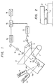
- FIG. 1 shows a film thickness measuring device which is proposed by the same applicant in a co-pending European Patent Application No.86 306054.7 filed on August 6, 1986, which was laid-open into public inspection as EP 0211654 on February 25, 1987.
- reference numeral 1 designates a rotary shaft which is rotated at a predetermined speed; 2, a light shielding board which is disposed in parallel with the rotary shaft 1 with a predetermined distance therebetween ; and 3, a sheet including a sheet member and a film formed thereon having a predetermined thickness, the thickness of the film being to be measured.
- the sheet 3 is conveyed at a speed equal to the rotation speed of the rotarys shaft 1 while being in close contact with the latter 1.
- laser beam generators 4 and 5 are arranged at predetermined angles with respect to each other, for generating laser beams 4a and 5a, respectively.
- a reflecting mirror 6 is provided to cause the laser beam 4a to scan a gap A shown in FIG. 2 between the surface of the rotary shaft 1 and the light shielding board 2. Further, the reflecting mirror 6 also causes the laser beam 5a to scan a gap B shown in FIG. 2 between the sheet 3 under measurement and the light shielding board 2.
- Reference numerals 7 and 8 designate lenses for converging the laser beams 4a and 5a, respectively, which have been reflected by the reflecting mirror 6; 9 and 10, lenses for converging the laser beams 4a, and 5a which have scanned the gaps A and B, respectively; 11 and 12, light receiving units; 13 and 14, counters; 15, an arithmetic unit; and 16, a display unit.
- the film thickness measuring device thus constructed operates as follows:
- the laser beams 4a and 5a generated by the laser beam generators 4 and 5 are directed to the reflecting mirror 6, so that they are caused to scan the respective gaps A and B at the same angular velocity.
- the laser beams 4a and 5a reflected by the mirror 6 are converged by the lenses 7 and 8 so that they are made minimum in beam diameter at the gaps A and B, respectively, and are run in a direction perpendicular to the rotary shaft 1; i.e., in the direction of the gaps at the predetermined speed.
- the light receiving units 11 and 12 receive the laser beams 4a and 5a which have passed through the gaps A and B, respectively.
- the output signals of the light receiving units 11 and 12 are pulse signals, the widths of which are proportional to the dimensions of the gaps A and B.
- the pulse signals widths are counted by the counters 13 and 14, the counted values of which are applied to the arithmetic unit 15 where the thickness is calculated using the counted values. The thickness thus calculated is displayed on the display unit 16.
- the film thickness t can be obtained by subtracting from the thickness t x of the sheet 3 thus calculated the thickness of the sheet member which has been known.
- the film thickness measuring device shown in FIG. 1 measures the thickness of the sheet member and that of the film formed thereon by referring to the dimension of the gap between the rotary shaft and the light shielding plate as a reference value. Therefore, the film thickness measuring device suffers from difficulties that, as the rotary shaft turns, the dimension of the gap varies with time because of the eccentricity or uneven surface of the rotary shaft and accordingly the measurement value also varies; that is, the measurement is not stable nor accurate.
- US-A-4 182 259 describes a device for controlling the thickness of a film on a roller.
- a beam of light is projhected so that a portion of the beam passes through a space between a shield member and the film, the shield member being placed parallel to the roller. The amount of light passing through the space is used to control the thickness of the film.
- GB-A-2 063 826 describes a device for determining the amount of webbing left on a roll of this material. Two light beams are directed over the outer diameter of the roll and the bore roller respectively. By comparing the two light beams, the thickness of webbing left on the roller can be estimated.
- an object of this invention to eliminate the above-described difficulties. More specifically, an object of the invention is to provide a film thickness measuring device in which the measurement is not affected by the eccentricity or uneven surface of the rotary shaft supporting the member.
- a film thickness measuring device for measuring the thickness t of a film formed on a sheet member which is conveyed with the rotation of a rotary shaft while being kept in close contact with said rotary shaft, comprising: a light shielding member disposed in parallel with said rotary shaft with a predetermined distance therebetween; means for generating first and second laser beams; means for receiving said first and second light beams after these have passed through the space between said shielding member and said shaft and converting said first and second laser beams into first and second electric signals, respectively; arithmetic means for carrying out an arithmetic operation to obtain the thickness t of said film characterized by means for repeatedly scanning across a first space between said light shielding member and the surface of said rotary shaft with the first laser beam and across a second space between said light shielding member and the surface of said film with the second laser beam; means for detecting the rotation speed of said rotary shaft, which is coupled to said arithmetic means, and counting means a counting the pulse widths of
- the scanning operation is carried out a plurality of times for every revolution of the rotary shaft, and the resultant data are averaged thereby to obtain the average of variation in dimension of the gap which attributes to the eccentricity or uneven surface of the rotary shaft, thereby to measure the thickness of the film stably at all times.
- the speed of rotation of the rotary shaft is detected with a rotation sensor coupled to the rotary shaft, so that the averaging operation is automatically carried out with high efficiency.
- reference numerals 1 through 16 designate those which have been designated by the same reference numerals in FIG. 2, and reference numeral 17 designates a rotation sensor for producing a pulse signal every revolution of the rotary shaft 1.
- the counted value a corresponding to the dimension of the gap A (FIG. 2) between the rotary shaft 1 and the light shielding board 2 changes in a range of from a maximum value a max to minimum value a min .
- the counted value b corresponding to the dimension of the gap B between the sheet 3 and the light shielding board 2 changes in a range of from a maximum value b max to a minimum value b min even if the sheet 3 is uniform in thickness.
- the thickness measured includes an error ranged from t xmax t o t xmin .
- the reflecting mirror of the scanning mechanism is operated at a speed higher than the speed or rotation of the rotary shaft 1, and the values a and b are measured several times per revolution of the rotary shaft 1.
- average values a av and b av are obtained from the values a and b thus measured, respectively.
- the error included in the thickness t x which attributes to the eccentricity or uneven surface of the rotary shaft, is minimized. If the averaging operation is effected for one revolution of the rotary shaft, more specifically, if the averaging operation is effected for data sampled during one revolution period thereof and the oldest data within data sampled is renewed in turn as new data is sampled, then the error can be completely eliminated.
- the rotation sensor 17 operates to produce a pulse signal every revolution of the rotary shaft 1 which is applied to the arithmetic unit 15. In the arithmetic unit 15, the data received during one revolution of the rotary shaft are averaged for calculation of the thickness. Therefore, no error attributing to the eccentricity or uneven surface of the rotary shaft 1 is included in the measurement value; that is, the thickness can be measured with high accuracy.
- the film thickness t can be obtained by subtracting from the thickness t x of the sheet 3 thus calculated the averaged thickness of the sheet member which has been known.
- reference characters 1 through 4, 4a, 5a and 6 through 17 designate those which have been designated by the same reference characters in FIG. 3, and reference characters 18 and 19 designate a half-mirror and a total reflection mirror, respectively.
- a laser beam from the laser beam source 4 is applied to the half-mirror 18, where it is divided into a component which passes through the half-mirror 18 and a component which is reflected by the half-mirror 18.
- the former laser beam is applied directly to the reflecting mirror 6.
- the latter laser beam is applied to the total reflection mirror 19, so that it is reflected by the latter 19 to form a predetermined angle, thus reaching the reflecting mechanism of the scanning mechanism.
- the two laser beams thus obtained act completely in the same manner as the two laser beams 4a and 5a from the two laser beam sources 4 and 5 in the film thickness measuring device described above.
- a high precision film thickness measuring device using two laser beams from one laser beam source has been provided according to the invention. If, in this connection, a semiconductor laser collimated is used as the laser beam source, then a film thickness measuring device small in size and low in manufacturing cost can be obtained according to the invention.
- a beam splitter i.e., the half-mirror is used to divide the laser beam into two laser beams, which are applied to the reflecting mirror.
- the same effect can be obtained by a device in which, as shown in FIG. 5, the laser beam from the light source 5, before being reflected from the reflecting mirror 6, is divided into two parts.
- the film thickness measuring device shown in FIG.5 operates as follows: The laser beam from the laser beam source 4 is applied to the reflecting mirror 6 so that it is deflected with time.
- the scanning beam is applied to the half-mirror 18 where it is divided into two parts: a first laser beam which passes through the half-mirror 18 and a second laser beam which is reflected by the half-mirror 18.
- the first laser beam is applied directly to the condenser lens 7, thus acting as a scanning beam.
- the second laser beam is applied to the total reflection mirror 19 so as to be reflected by the latter 19.
- the second laser beam thus reflected is applied to the condenser lens 8, thus operating as a scanning beam.
- the two scanning beams thus provided act completely in the same manner as the two laser beams 4a and 5a from the two laser beam sources 4 and 5 in the film thickness measuring device with the same effects described above.
- the rotation sensor coupled to the rotation shaft outputs one pulse per revolution of the rotary shaft, and the data received through scanning during the time interval between two pulses which are produced successively by the rotation sensor are averaged to calculate the thickness. Therefore, the error attributing to the eccentricity or uneven surface of the rotary shaft is completely removed from the measurement value.
- the film thickness measuring device of the invention can measure the thickness of a film with high accuracy.
- the laser beam emitted from one laser beam generator after being deflected, is split into two laser beams, and the direction of advancement of one of the two laser beams is changed with the total reflection mirror; that is, two laser beams different in an advancement direction are obtained from one laser beam source. Therefore, the device of the invention is simple in construction and small in size.
- the amount of heat generated by the device using a single laser beam generator is reduced to half of that generated by an ordinary film thickness measuring device using two independent laser beam generators.
- the device of the invention is more stable in characteristic than the ordinary device.
Description
- This invention relates to a film thickness measuring device for measuring the thickness of a film formed on a sheet member in a sheet member manufacturing line such as a magnetic tape manufacturing line.
- FIG. 1 shows a film thickness measuring device which is proposed by the same applicant in a co-pending European Patent Application No.86 306054.7 filed on August 6, 1986, which was laid-open into public inspection as EP 0211654 on February 25, 1987.
- In FiG. 1, reference numeral 1 designates a rotary shaft which is rotated at a predetermined speed; 2, a light shielding board which is disposed in parallel with the rotary shaft 1 with a predetermined distance therebetween ; and 3, a sheet including a sheet member and a film formed thereon having a predetermined thickness, the thickness of the film being to be measured. The
sheet 3 is conveyed at a speed equal to the rotation speed of the rotarys shaft 1 while being in close contact with the latter 1. - Further in FIG. 1,
laser beam generators laser beams mirror 6 is provided to cause thelaser beam 4a to scan a gap A shown in FIG. 2 between the surface of the rotary shaft 1 and thelight shielding board 2. Further, the reflectingmirror 6 also causes thelaser beam 5a to scan a gap B shown in FIG. 2 between thesheet 3 under measurement and thelight shielding board 2. Reference numerals 7 and 8 designate lenses for converging thelaser beams mirror 6; 9 and 10, lenses for converging thelaser beams - The film thickness measuring device thus constructed operates as follows:
- The
laser beams laser beam generators mirror 6, so that they are caused to scan the respective gaps A and B at the same angular velocity. Thelaser beams mirror 6 are converged by the lenses 7 and 8 so that they are made minimum in beam diameter at the gaps A and B, respectively, and are run in a direction perpendicular to the rotary shaft 1; i.e., in the direction of the gaps at the predetermined speed. In this operation, thelight receiving units laser beams light receiving units counters arithmetic unit 15 where the thickness is calculated using the counted values. The thickness thus calculated is displayed on thedisplay unit 16. - The thickness tx of the
sheet member 3 under measurement can be obtained from the following equation(1):
counter 13, b is the counted value of thecounter 14, and to is the dimension of the gap A which has been set. - The film thickness t can be obtained by subtracting from the thickness tx of the
sheet 3 thus calculated the thickness of the sheet member which has been known. - As was described above, the film thickness measuring device shown in FIG. 1 measures the thickness of the sheet member and that of the film formed thereon by referring to the dimension of the gap between the rotary shaft and the light shielding plate as a reference value. Therefore, the film thickness measuring device suffers from difficulties that, as the rotary shaft turns, the dimension of the gap varies with time because of the eccentricity or uneven surface of the rotary shaft and accordingly the measurement value also varies; that is, the measurement is not stable nor accurate.
- US-A-4 182 259 describes a device for controlling the thickness of a film on a roller. A beam of light is projhected so that a portion of the beam passes through a space between a shield member and the film, the shield member being placed parallel to the roller. The amount of light passing through the space is used to control the thickness of the film.
- GB-A-2 063 826 describes a device for determining the amount of webbing left on a roll of this material. Two light beams are directed over the outer diameter of the roll and the bore roller respectively. By comparing the two light beams, the thickness of webbing left on the roller can be estimated.
- Accordingly, an object of this invention to eliminate the above-described difficulties. More specifically, an object of the invention is to provide a film thickness measuring device in which the measurement is not affected by the eccentricity or uneven surface of the rotary shaft supporting the member.
- The object of the present invention is solved by a film thickness measuring device for measuring the thickness t of a film formed on a sheet member which is conveyed with the rotation of a rotary shaft while being kept in close contact with said rotary shaft, comprising: a light shielding member disposed in parallel with said rotary shaft with a predetermined distance therebetween; means for generating first and second laser beams; means for receiving said first and second light beams after these have passed through the space between said shielding member and said shaft and converting said first and second laser beams into first and second electric signals, respectively; arithmetic means for carrying out an arithmetic operation to obtain the thickness t of said film characterized by means for repeatedly scanning across a first space between said light shielding member and the surface of said rotary shaft with the first laser beam and across a second space between said light shielding member and the surface of said film with the second laser beam; means for detecting the rotation speed of said rotary shaft, which is coupled to said arithmetic means, and counting means a counting the pulse widths of the signals from the receiving and converting means, being adapted to count the pulse widths of a plurality of said first and second electric signals for a period of time defined by the output of said rotation speed detecting means; said arithmetic means being adapted to average said plurality of first and second counted values so as to obtain the thickness of said film based on said first and second averaged values.
- The scanning operation is carried out a plurality of times for every revolution of the rotary shaft, and the resultant data are averaged thereby to obtain the average of variation in dimension of the gap which attributes to the eccentricity or uneven surface of the rotary shaft, thereby to measure the thickness of the film stably at all times. The speed of rotation of the rotary shaft is detected with a rotation sensor coupled to the rotary shaft, so that the averaging operation is automatically carried out with high efficiency.
- In the accompanying drawings:
- FIGS. 1 and 2 are explanatory diagrams showing the arrangement of a film thickness measuring device which has been proposed in the co-pending application;
- FIG. 3 is an explanatory diagram showing the first embodiment of the present invention; and
- FIGS. 4 and 5 are explanatory diagram showing the second and third embodiments of the present invention.
- A preferred embodiment of this invention will be described with reference to FIG. 3. In FIG.3, reference numerals 1 through 16 designate those which have been designated by the same reference numerals in FIG. 2, and
reference numeral 17 designates a rotation sensor for producing a pulse signal every revolution of the rotary shaft 1. - The operation of the embodiment thus constructed will be described. In the rotary shaft 1, in general, its surface is uneven, and its axis of rotation is not coincident with the central axis of the rotary shaft 1; that is, the former is eccentric from the latter.
- Because of these facts, the counted value a corresponding to the dimension of the gap A (FIG. 2) between the rotary shaft 1 and the
light shielding board 2 changes in a range of from a maximum value a max to minimum value a min. Similarly, the counted value b corresponding to the dimension of the gap B between thesheet 3 and thelight shielding board 2 changes in a range of from a maximum value b max to a minimum value b min even if thesheet 3 is uniform in thickness. Therefore, the thickness tx of the sheet calculated according to the equation (1) falls in a range of from a maximum value txmas to a minimum value txmin which are expressed by the following equations (2) and (3):

- Accordingly, the thickness measured includes an error ranged from txmax to txmin.
- In the film thickness measuring device of the invention, the reflecting mirror of the scanning mechanism is operated at a speed higher than the speed or rotation of the rotary shaft 1, and the values a and b are measured several times per revolution of the rotary shaft 1. And in the
arithmetic unit 15, average values a av and b av are obtained from the values a and b thus measured, respectively. These averaged values a av and b av are used to calculate the thickness tx according to the following expression:
- As a result, the error included in the thickness tx, which attributes to the eccentricity or uneven surface of the rotary shaft, is minimized. If the averaging operation is effected for one revolution of the rotary shaft, more specifically, if the averaging operation is effected for data sampled during one revolution period thereof and the oldest data within data sampled is renewed in turn as new data is sampled, then the error can be completely eliminated. The
rotation sensor 17 operates to produce a pulse signal every revolution of the rotary shaft 1 which is applied to thearithmetic unit 15. In thearithmetic unit 15, the data received during one revolution of the rotary shaft are averaged for calculation of the thickness. Therefore, no error attributing to the eccentricity or uneven surface of the rotary shaft 1 is included in the measurement value; that is, the thickness can be measured with high accuracy. - As mentioned above, the film thickness t can be obtained by subtracting from the thickness tx of the
sheet 3 thus calculated the averaged thickness of the sheet member which has been known. - A second embodiment of the invention will be described with reference to FIG. 4. In FIG. 4, reference characters 1 through 4, 4a, 5a and 6 through 17 designate those which have been designated by the same reference characters in FIG. 3, and
reference characters - The operation of the second embodiment thus constructed will be described. A laser beam from the
laser beam source 4 is applied to the half-mirror 18, where it is divided into a component which passes through the half-mirror 18 and a component which is reflected by the half-mirror 18. The former laser beam is applied directly to the reflectingmirror 6. The latter laser beam is applied to thetotal reflection mirror 19, so that it is reflected by the latter 19 to form a predetermined angle, thus reaching the reflecting mechanism of the scanning mechanism. The two laser beams thus obtained act completely in the same manner as the twolaser beams laser beam sources - In the above-described embodiment, a beam splitter, i.e., the half-mirror is used to divide the laser beam into two laser beams, which are applied to the reflecting mirror. However, the same effect can be obtained by a device in which, as shown in FIG. 5, the laser beam from the
light source 5, before being reflected from the reflectingmirror 6, is divided into two parts. - The film thickness measuring device shown in FIG.5 operates as follows: The laser beam from the
laser beam source 4 is applied to the reflectingmirror 6 so that it is deflected with time. The scanning beam is applied to the half-mirror 18 where it is divided into two parts: a first laser beam which passes through the half-mirror 18 and a second laser beam which is reflected by the half-mirror 18. The first laser beam is applied directly to the condenser lens 7, thus acting as a scanning beam. On the other hand, the second laser beam is applied to thetotal reflection mirror 19 so as to be reflected by the latter 19. The second laser beam thus reflected is applied to the condenser lens 8, thus operating as a scanning beam. The two scanning beams thus provided act completely in the same manner as the twolaser beams laser beam sources - As described above, in the film thickness measuring device of the invention, the rotation sensor coupled to the rotation shaft outputs one pulse per revolution of the rotary shaft, and the data received through scanning during the time interval between two pulses which are produced successively by the rotation sensor are averaged to calculate the thickness. Therefore, the error attributing to the eccentricity or uneven surface of the rotary shaft is completely removed from the measurement value. Thus, the film thickness measuring device of the invention can measure the thickness of a film with high accuracy.
- Further, in the film thickness measuring device of the invention, the laser beam emitted from one laser beam generator, after being deflected, is split into two laser beams, and the direction of advancement of one of the two laser beams is changed with the total reflection mirror; that is, two laser beams different in an advancement direction are obtained from one laser beam source. Therefore, the device of the invention is simple in construction and small in size.
- For the same reason, the amount of heat generated by the device using a single laser beam generator is reduced to half of that generated by an ordinary film thickness measuring device using two independent laser beam generators. Thus, the device of the invention is more stable in characteristic than the ordinary device.
Claims (7)
a light shielding member (2) disposed in parallel with said rotary shaft (1) with a predetermined distance therebetween;
means (4,5,18,19) for generating first and second laser beams (4a,5a);
means for receiving (11,12) said first and second laser beams after these have passed through the space between said shielding member (2) and said shaft (1) and converting said first and second laser beams into first and second electric signals, respectively; and arithmetic means (15) for carrying out an arithmetic operation to obtain the thickness t of said film;
characterized by
means (6) for repeatedly scanning across a first space between said light shielding member (2) and the surface of said rotary shaft (1) with the first laser beam (4a) and across a second space between said light shielding member (2) and the surface of said film with the second laser beam (5a);
means (17) for detecting the rotation speed of said rotary shaft (1), which is coupled to said arithmetic means (15); and
counting means (13, 14) for counting the pulse widths of the signals from the receiving and converting means (11,12) being adapted to count the pulse widths of a plurality of said first and second electric signals for a period of time defined by the output of said rotation speed detecting means (17); said arithmetic means (15) being adapted to average said plurality of first and second counted values so as to obtain the thickness of said film based on said first and second averaged values.
Applications Claiming Priority (4)
| Application Number | Priority Date | Filing Date | Title |
|---|---|---|---|
| JP6524986U JPS62176706U (en) | 1986-04-29 | 1986-04-29 | |
| JP65249/86 | 1986-04-29 | ||
| JP100067/86 | 1986-04-29 | ||
| JP10006786A JPS62255807A (en) | 1986-04-29 | 1986-04-29 | Measuring instrument for thickness of film |
Publications (3)
| Publication Number | Publication Date |
|---|---|
| EP0243961A2 EP0243961A2 (en) | 1987-11-04 |
| EP0243961A3 EP0243961A3 (en) | 1989-03-22 |
| EP0243961B1 true EP0243961B1 (en) | 1992-03-11 |
Family
ID=26406376
Family Applications (1)
| Application Number | Title | Priority Date | Filing Date |
|---|---|---|---|
| EP87106268A Expired - Lifetime EP0243961B1 (en) | 1986-04-29 | 1987-04-29 | Film thickness measuring device |
Country Status (5)
| Country | Link |
|---|---|
| US (1) | US4748331A (en) |
| EP (1) | EP0243961B1 (en) |
| KR (1) | KR900003208B1 (en) |
| CA (1) | CA1292803C (en) |
| DE (1) | DE3777232D1 (en) |
Families Citing this family (8)
| Publication number | Priority date | Publication date | Assignee | Title |
|---|---|---|---|---|
| KR920004750B1 (en) * | 1988-01-19 | 1992-06-15 | 미쓰비시전기 주식회사 | Thickness measuring method |
| DE4209314C1 (en) * | 1992-03-23 | 1993-02-11 | Fagus-Grecon Greten Gmbh & Co Kg, 3220 Alfeld, De | |
| US5622268A (en) * | 1994-11-30 | 1997-04-22 | Heidelberg Finishing Systems, Inc. | Apparatus for calipering a collated assemblage |
| DE10054227A1 (en) * | 2000-11-02 | 2002-08-01 | Musa Kazalan | Measuring device for monitoring the outer contour of profiles during production |
| US7824730B2 (en) * | 2007-08-31 | 2010-11-02 | United Technologies Corporation | Method and apparatus for measuring coating thickness with a laser |
| US9109330B2 (en) * | 2009-03-09 | 2015-08-18 | Honeywell International Inc. | Apparatus and method for measuring properties of unstabilized moving sheets |
| US9403259B2 (en) | 2013-03-15 | 2016-08-02 | United Technologies Corporation | Removing material from a workpiece with a water jet |
| CN110142954A (en) * | 2019-03-26 | 2019-08-20 | 宁波太古新材料科技有限公司 | A kind of protective film corona treatment plant automatically adjusting corona distance |
Family Cites Families (6)
| Publication number | Priority date | Publication date | Assignee | Title |
|---|---|---|---|---|
| US3518441A (en) * | 1968-01-24 | 1970-06-30 | Neotec Corp | Optical gage for measuring the thickness of a continuous web |
| DE2352694C2 (en) * | 1973-10-20 | 1983-05-19 | Robert Bosch Gmbh, 7000 Stuttgart | Digital circuit arrangement for triggering an operating process, in particular the ignition process of an internal combustion engine |
| US4182259A (en) * | 1978-10-04 | 1980-01-08 | The Dow Chemical Company | Apparatus for measuring coating thickness on an applicator roll |
| JPS5667704A (en) * | 1979-11-08 | 1981-06-08 | Kobe Steel Ltd | Automatic nondestructive measuring method for eccentricity of coated welding rod |
| GB2063826B (en) * | 1979-11-19 | 1982-10-06 | Ciba Geigy Ag | Controlling winding or unwinding of webs rolls |
| US4730116A (en) * | 1985-08-06 | 1988-03-08 | Mitsubishi Denki Kabushiki Kaisha | Sheet thickness measuring apparatus by optical scanning |
-
1987
- 1987-04-23 KR KR1019870003914A patent/KR900003208B1/en not_active IP Right Cessation
- 1987-04-28 CA CA000535948A patent/CA1292803C/en not_active Expired - Fee Related
- 1987-04-29 EP EP87106268A patent/EP0243961B1/en not_active Expired - Lifetime
- 1987-04-29 DE DE8787106268T patent/DE3777232D1/en not_active Expired - Fee Related
- 1987-04-29 US US07/043,711 patent/US4748331A/en not_active Expired - Fee Related
Also Published As
| Publication number | Publication date |
|---|---|
| CA1292803C (en) | 1991-12-03 |
| EP0243961A2 (en) | 1987-11-04 |
| KR870010382A (en) | 1987-11-30 |
| DE3777232D1 (en) | 1992-04-16 |
| EP0243961A3 (en) | 1989-03-22 |
| US4748331A (en) | 1988-05-31 |
| KR900003208B1 (en) | 1990-05-10 |
Similar Documents
| Publication | Publication Date | Title |
|---|---|---|
| US3807870A (en) | Apparatus for measuring the distance between surfaces of transparent material | |
| EP0250764B1 (en) | Film thickness measuring method and device therefor | |
| EP0243961B1 (en) | Film thickness measuring device | |
| US3994599A (en) | Method and apparatus for measuring wall thickness and concentricity of tubular glass articles | |
| JPS6037907B2 (en) | Distance measurement method | |
| US4678337A (en) | Laser based gaging system and method of using same | |
| US4869110A (en) | Laser strain extensometer for material testing | |
| JPS6341484B2 (en) | ||
| EP0339985B1 (en) | Method for measuring film thickness | |
| JPH06167327A (en) | Measuring method for camber | |
| KR920004750B1 (en) | Thickness measuring method | |
| JPH0441923B2 (en) | ||
| JP2799492B2 (en) | Position or length measuring device | |
| JP2903283B2 (en) | Fine wire diameter measuring device | |
| JPS6234005A (en) | Apparatus for measuring thickness of film | |
| JPH0441924B2 (en) | ||
| JP2593100B2 (en) | Method of monitoring the amount of exposure light of a characteristic evaluation device for an electrophotographic photosensitive drum | |
| JPS6353406A (en) | Film thickness measuring apparatus | |
| JPH05231856A (en) | Thickness measuring instrument | |
| JPH0441925B2 (en) | ||
| SE414225B (en) | Arrangement for dimension measuring by means of a laser beam | |
| JPH06137818A (en) | Laser utilization type measuring device | |
| JPH01259206A (en) | Film thickness measuring instrument | |
| JPH0861943A (en) | X-ray measuring device | |
| JPH0718981B2 (en) | Optical deflector evaluation device |
Legal Events
| Date | Code | Title | Description |
|---|---|---|---|
| PUAI | Public reference made under article 153(3) epc to a published international application that has entered the european phase |
Free format text: ORIGINAL CODE: 0009012 |
|
| AK | Designated contracting states |
Kind code of ref document: A2 Designated state(s): DE FR GB SE |
|
| PUAL | Search report despatched |
Free format text: ORIGINAL CODE: 0009013 |
|
| AK | Designated contracting states |
Kind code of ref document: A3 Designated state(s): DE FR GB SE |
|
| 17P | Request for examination filed |
Effective date: 19890407 |
|
| 17Q | First examination report despatched |
Effective date: 19901119 |
|
| GRAA | (expected) grant |
Free format text: ORIGINAL CODE: 0009210 |
|
| AK | Designated contracting states |
Kind code of ref document: B1 Designated state(s): DE FR GB SE |
|
| REF | Corresponds to: |
Ref document number: 3777232 Country of ref document: DE Date of ref document: 19920416 |
|
| ET | Fr: translation filed | ||
| PLBE | No opposition filed within time limit |
Free format text: ORIGINAL CODE: 0009261 |
|
| STAA | Information on the status of an ep patent application or granted ep patent |
Free format text: STATUS: NO OPPOSITION FILED WITHIN TIME LIMIT |
|
| 26N | No opposition filed | ||
| PGFP | Annual fee paid to national office [announced via postgrant information from national office to epo] |
Ref country code: FR Payment date: 19930408 Year of fee payment: 7 |
|
| PGFP | Annual fee paid to national office [announced via postgrant information from national office to epo] |
Ref country code: SE Payment date: 19930419 Year of fee payment: 7 Ref country code: GB Payment date: 19930419 Year of fee payment: 7 |
|
| PGFP | Annual fee paid to national office [announced via postgrant information from national office to epo] |
Ref country code: DE Payment date: 19930506 Year of fee payment: 7 |
|
| PG25 | Lapsed in a contracting state [announced via postgrant information from national office to epo] |
Ref country code: GB Effective date: 19940429 |
|
| PG25 | Lapsed in a contracting state [announced via postgrant information from national office to epo] |
Ref country code: SE Effective date: 19940430 |
|
| PG25 | Lapsed in a contracting state [announced via postgrant information from national office to epo] |
Ref country code: FR Effective date: 19941229 |
|
| PG25 | Lapsed in a contracting state [announced via postgrant information from national office to epo] |
Ref country code: DE Effective date: 19950103 |
|
| GBPC | Gb: european patent ceased through non-payment of renewal fee |
Effective date: 19940429 |
|
| EUG | Se: european patent has lapsed |
Ref document number: 87106268.3 Effective date: 19941110 |
|
| REG | Reference to a national code |
Ref country code: FR Ref legal event code: ST |