EP0243946A2 - Kraftstoffsteuereinrichtung für Brennkraftmaschine - Google Patents
Kraftstoffsteuereinrichtung für Brennkraftmaschine Download PDFInfo
- Publication number
- EP0243946A2 EP0243946A2 EP87106216A EP87106216A EP0243946A2 EP 0243946 A2 EP0243946 A2 EP 0243946A2 EP 87106216 A EP87106216 A EP 87106216A EP 87106216 A EP87106216 A EP 87106216A EP 0243946 A2 EP0243946 A2 EP 0243946A2
- Authority
- EP
- European Patent Office
- Prior art keywords
- output
- engine
- pulse
- afs
- intake
- Prior art date
- Legal status (The legal status is an assumption and is not a legal conclusion. Google has not performed a legal analysis and makes no representation as to the accuracy of the status listed.)
- Granted
Links
Images


Classifications
-
- F—MECHANICAL ENGINEERING; LIGHTING; HEATING; WEAPONS; BLASTING
- F02—COMBUSTION ENGINES; HOT-GAS OR COMBUSTION-PRODUCT ENGINE PLANTS
- F02D—CONTROLLING COMBUSTION ENGINES
- F02D41/00—Electrical control of supply of combustible mixture or its constituents
- F02D41/20—Output circuits, e.g. for controlling currents in command coils
-
- F—MECHANICAL ENGINEERING; LIGHTING; HEATING; WEAPONS; BLASTING
- F02—COMBUSTION ENGINES; HOT-GAS OR COMBUSTION-PRODUCT ENGINE PLANTS
- F02D—CONTROLLING COMBUSTION ENGINES
- F02D41/00—Electrical control of supply of combustible mixture or its constituents
- F02D41/30—Controlling fuel injection
- F02D41/32—Controlling fuel injection of the low pressure type
- F02D41/34—Controlling fuel injection of the low pressure type with means for controlling injection timing or duration
- F02D41/345—Controlling injection timing
-
- F—MECHANICAL ENGINEERING; LIGHTING; HEATING; WEAPONS; BLASTING
- F02—COMBUSTION ENGINES; HOT-GAS OR COMBUSTION-PRODUCT ENGINE PLANTS
- F02D—CONTROLLING COMBUSTION ENGINES
- F02D41/00—Electrical control of supply of combustible mixture or its constituents
- F02D41/02—Circuit arrangements for generating control signals
- F02D41/04—Introducing corrections for particular operating conditions
- F02D41/06—Introducing corrections for particular operating conditions for engine starting or warming up
- F02D41/062—Introducing corrections for particular operating conditions for engine starting or warming up for starting
- F02D41/064—Introducing corrections for particular operating conditions for engine starting or warming up for starting at cold start
-
- F—MECHANICAL ENGINEERING; LIGHTING; HEATING; WEAPONS; BLASTING
- F02—COMBUSTION ENGINES; HOT-GAS OR COMBUSTION-PRODUCT ENGINE PLANTS
- F02D—CONTROLLING COMBUSTION ENGINES
- F02D41/00—Electrical control of supply of combustible mixture or its constituents
- F02D41/30—Controlling fuel injection
- F02D41/32—Controlling fuel injection of the low pressure type
- F02D41/34—Controlling fuel injection of the low pressure type with means for controlling injection timing or duration
-
- F—MECHANICAL ENGINEERING; LIGHTING; HEATING; WEAPONS; BLASTING
- F02—COMBUSTION ENGINES; HOT-GAS OR COMBUSTION-PRODUCT ENGINE PLANTS
- F02D—CONTROLLING COMBUSTION ENGINES
- F02D41/00—Electrical control of supply of combustible mixture or its constituents
- F02D41/30—Controlling fuel injection
- F02D41/32—Controlling fuel injection of the low pressure type
- F02D41/36—Controlling fuel injection of the low pressure type with means for controlling distribution
-
- F—MECHANICAL ENGINEERING; LIGHTING; HEATING; WEAPONS; BLASTING
- F02—COMBUSTION ENGINES; HOT-GAS OR COMBUSTION-PRODUCT ENGINE PLANTS
- F02B—INTERNAL-COMBUSTION PISTON ENGINES; COMBUSTION ENGINES IN GENERAL
- F02B75/00—Other engines
- F02B75/02—Engines characterised by their cycles, e.g. six-stroke
- F02B2075/022—Engines characterised by their cycles, e.g. six-stroke having less than six strokes per cycle
- F02B2075/027—Engines characterised by their cycles, e.g. six-stroke having less than six strokes per cycle four
-
- Y—GENERAL TAGGING OF NEW TECHNOLOGICAL DEVELOPMENTS; GENERAL TAGGING OF CROSS-SECTIONAL TECHNOLOGIES SPANNING OVER SEVERAL SECTIONS OF THE IPC; TECHNICAL SUBJECTS COVERED BY FORMER USPC CROSS-REFERENCE ART COLLECTIONS [XRACs] AND DIGESTS
- Y02—TECHNOLOGIES OR APPLICATIONS FOR MITIGATION OR ADAPTATION AGAINST CLIMATE CHANGE
- Y02T—CLIMATE CHANGE MITIGATION TECHNOLOGIES RELATED TO TRANSPORTATION
- Y02T10/00—Road transport of goods or passengers
- Y02T10/10—Internal combustion engine [ICE] based vehicles
- Y02T10/40—Engine management systems
Definitions
- the present invention relates to a fuel injection control for an internal combustion engine.
- the so-called "multi-point system” in which a fuel injector is provided for each cylinder is generally used and the fuel injectors for respective cylinders are actuated according to predetermined crank angles to inject fuel sequentially.
- This system makes it possible to make a width range of pulse for driving the injectors wide and to thereby facilitate an air-fuel ratio control.
- the width of pulse for driving the injectors for, for example, a 4-cycle, 2-liter engine may be around 15m sec at a heavy load under a complete idling condition and around 200m sec during a starting period of the engine at a very low temperature. Therefore, a large dynamic range of drive time is required and a control device for controlling such large dynamic range must have a complicated and expensive construction due to the fact that a timer thereof must have a large number of bits, etc.
- An object of the present invention is to provide a fuel control system for internal combustion engine, which has a simplified and inexpensive construction.
- the above object can be achieved by driving fuel injectors a plurality of times per air-intake operation with pulses each having a width smaller than that of injector driving pulse at start time of an engine at low temperature. That is, in the present invention each fuel injector is driven once for each air-intake period during a normal engine operation and, when the pulse width is larger in such a time as when the engine at low temperature is started, each fuel injector is driven several times for each air-intake period with pulses each having a smaller width than the latter pulse.
- FIG. 1 which shows a construction of a fuel control device according to the present invention
- an internal combustion engine is associated with an air cleaner 10, a surge tank 11, a throttle valve 12, a Kalman type air-flow sensor (AFS) 13, fuel injectors 14 for each of the cylinders of the engine 1, a suction pipe 15, an exhaust pipe 16, a crank angle sensor 17, a water temperature sensor 18 and an ignition switch 19.
- AFS Kalman type air-flow sensor
- the AFS 13 responds to an intake air flow for producing pulses the number of which indicates an amount of air and the crank angle sensor 17 responds to an engine revolution for producing an SGT (representative of crank angle) pulse, in this case, a crank angle from a leading edge to a trailing edge of the pulse being 180°, and produces an SGC signal (cylinder identifying code signal) which is high during a compression stroke of, for example, a first cylinder.
- An AN detector 20 responds to outputs of the AFS 13 and the crank angle sensor 17 to count the output pulses from the AFS 13 fallen within a predetermined crank angle of the engine 1.
- the control device 22 receives the outputs of the AN operation device 21, the crank angle sensor 17, the water temperature sensor 18 such as thermistor for detecting a coolant temperature of the engine 1 and an output of a starter switch 19 for sensing an engine starting state to control a driving time of the injectors 14 correspondingly to the air intake amount of the engine 1 to thereby control an amount of fuel to be supplied to the engine l.
- Fig. 2 shows the emobdiment in Fig. 1 in more detail, in which a controller 30 receives the outputs of the AFS 13, the crank angle sensor 17, the temperature sensor 18 and the starter switch 19 to control the four injectors 14 provided for the four cylinders of the engine, respectively.
- the controller 30 corresponds to a combination of the AN detecter 20, the AN operation circuit 21 and the control device 22 and comprises a microcomputer (CPU) 40 including a ROM 41 and a RAM 42.
- CPU microcomputer
- a divide-by-2 frequency divider 31 has an input connected to the output of the AFS 13 and an exclusive OR gate 32 has one input connected to an output of the divider 31, the other input connected to an input P l of the CPU 40 and an output connected to a counter 33 and to an input P3 of the CPU 40.
- An interface 34 is connected between the temperature sensor 18 and an analog to digital (A/D) converter 35.
- the controller 30 further includes a wave-shaper 36 which receives the SGT output of the crank angle sensor 17 and provides an output to be supplied to an interrupt input P4 of the CPU 40 and to the counter 33, another wave-shaper 51 which receives the SGC output of the crank angle sensor 17 and provides an output to be supplied to a port of the CPU 40.
- the starter switch 19 is connected through an interface 46 to another port of the CPU 40.
- the controller 30 further includes a timer 38 connected to an interrupt input P5 of the CPU 40, an A/D converter 39 for converting a battery voltage V B into a digital value and timers 43 to 46 provided between the CPU 40 and drivers 47 to 50, respectively. Outputs of the drivers 47 to 50 are commonly connected to the injectors 14.
- the output of the AFS 13 is frequency-divided by 2 by the frequency divider 31 and supplied through a gate 32 which is controlled by the CPU 40 to the counter 33 which measures a time period between trailing edges of the outputs of the gate 32.
- the CPU 40 is supplied at its interrupt input P3 with the trailing edge of the output of the gate 32 so that it is interrupted every or every half output pulse period of the AFS 13 to measure the period of the counter 33.
- the output of the temperature sensor 18 is converted by the interface 34 into a voltage which is converted by the A/D converter 35 into a digital value every predetermined time, which is supplied to the CPU 40.
- the SGT output of the crank angle sensor 17 is supplied through the wave-shaper 36 to the interrupt input P4 of the CPU 40 and to the counter 37.
- the CPU 40 performs an interrupt operation every leading edge of the SGT output of the crank angle sensor 17 to detect a period between adjacent leading edges of the SGT output from the counter 37.
- the CPU 40 also checks the SGC signal of the crank angle sensor 17 every leading edge of the SGT signal to detect the compression stroke of the first cylinder.
- the CPU 40 judges the starter switch 19 as being on when the output of the interface 46 is high (H).
- the time 38 produces an interrupt signal every predetermined time, which is supplied to the interrupt input P5 of the CPU 40.
- the A/D converter 39 converts the battery voltage into a digital value and the CPU 40 takes a battery voltage data in every predetermined time.
- the timers 43 to 46 are preset by the CPU 40 and are triggered by an output port P2 of the CPU 40 to provide pulses of a predetermined width which drive the injectors 14 thorugh the drivers 47 to 50.
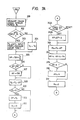
- Fig. 4 is a main program of the CPU 40.
- the RAM 42 and input/output ports are initialized at step 100.
- the output of the water temperature sensor 18 is analog/digital converted at step 101 and the latter is stored in the RAM 42 as WT.
- the battery voltage is A/D converted, which is stored in the RAM 42 as VB.
- an operation of 30/T R is performed where T r is a period of the crank angle sensor 17 to calculate the revolution number N e of the engine.
- a fundamental drive time conversion coefficient K p is calculated as a function f l of the output frequency F a , the function f l being shown in Fig. 5.
- the drive time conversion coefficient K p is corrected by the water temperature data WT at step 106 and the corrected drive time conversion coefficient K l is stored in the RAM 42.
- a data table f3 preliminarily stored in the ROM 41 is mapped by the battery voltage data VB at step 107 to calculate a redundant time T D which is stored in the RAM 42. Thereafter, the operation from the step 101 to the step 107 is repeated.
- Fig. 6 shows an interrupt operation for the interrupt input P3, i.e., the output signal of the AFS 13.
- an output T F of the counter 33 is detected to clear the latter.
- the output T F is a period between leading edges of the gate 32.
- the pulse data P R is obtained by accumulating pulses each supplied from the AFS 13 within a time between adjacent leading edges of the outputs of the crank angle sensor 17.
- each output pulse from the crank angle sensor 17 is made correspondent to 156 pulses in order to maintain an accuracy of operation in the CPU 40.
- the accumulation pulse data P R is added to the remaining pulse data P D at step 206.
- the remaining pulse data P D is set as 156.
- step 210 When the preceding frequency division flag is cleared in step 210, the operation is shifted to step 211 and, when it is set in step 210, the operation is shifted to step 216.
- step 211 the current AFS pulse period T F is divided by 2 and the result is stored in TA of the RAM 42.
- step 216 the T F is stored in the TA completing an interrupt operation.
- step 212 the frequency division flag is cleared and, if the preceding frequency division flag is set in step 213, the operation is shifted to step 214. If the flag is reset in the step 213, the operation is shifted to step 217.
- step 214 the current AFS pulse period T F is divided by 2 and the result is stored in the TA of the RAM 42.
- step 217 the T F is stored in the TA and in step 215 the P l is inverted completing an interrupt operation.
- a signal is inputted to the interrupt input P3 at a timing corresponding to a half of the output pulse frequency of the AFS 13 and, in the case of the operation at the step 212, a signal is inputted to the interrupt input P3 at a timing corresponding to the output pulse frequency of the AFS 13.
- Figs. 7A and 7B form a flow chart showing an interrupt operation when an interrupt signal is generated at the interrupt input P4 of the CPU 40 due to an output of the crank angle sensor 17.
- a period between adjacent leading edges of the output pulses from the crank angle sensor 17 is readin in the counter 37 which is stored in the RAM 42 as the period T R and then the counter 37 is cleared.
- it is checked whether or not there is output pulse of the AFS 13 within the period T R .
- the time difference ⁇ t is put as a period T S .
- the period T R is made correspondent to the period T S , at step 304.
- the period T R is the period T S .
- a calculation of 156 ⁇ T S /T A is performed to convert the time difference ⁇ t into the output pulse data ⁇ P of the AFS 13.
- the pulse data ⁇ P is calculated under an assumption that a preceding output pulse period of the AFS 13 is the same as a current output pulse period of the AFS 13.
- the pulse data ⁇ P is compared with 156. When it is smaller than 156, the operation is shifted to step 308 and, when larger than 156, the data ⁇ P is clipped to 156 at step 307.
- the remaining pulse data P D is subtracted by the pulse data ⁇ P to update the remaining pulse data.
- a sum of the accumulated pulse data P R and the pulse data ⁇ P is obtained which is a new accumulated pulse data P R .
- the latter data corresponds to the number of pulses to be considered as being outputted by the AFS 13 during a current period between a preceding leading edge and a current leading edge of pulses from the crank angle sensor 17.
- a calculation of the equation (1) is performed. That is, the calculation of K l ⁇ AN + K2 ⁇ P R is performed where AN and P R are a load data and a pulse data up to the leading edge of the preceding output of the crank angle sensor 17, respectively, and a result thereof is set as a new load data AN.
- the new load data AN is checked at step 315 whether or not it is larger than a predetermined value ⁇ . If yes, it is clipped to the value ⁇ at step 316 so that the load data AN can not be larger than an actual value even when the engine l is operating with the throttle being fully opened.
- the accumulated pulse data P R is cleared.
- step 318 it is checked at step 318 whether the SGC signal (cylinder recognition signal) is high or low.
- the content of the cylinder counter is made +1 at step 319 and, when it is high, the cylinder counter is cleared at step 320 since the SGC signal is always high during compression stroke of the cylinder No. 1.
- step 329 it is checked at step 329 whether or not the content of the cylinder counter is 0. If yes, the fuel injector 14 for the cylinder No. 4 is driven at step 333. If no, then it is checked at step 330 whether or not the content of the cylinder counter is l. If yes, the fuel injector 14 for the cylinder No. 3 is driven at step 334 and, if no, it is checked at step 331 whether or not the content of the cylinder counter is 2. If yes, the fuel injector 14 for the cylinder No. 2 is driven at step 335 and, if no, the cylinder No. 1 is driven at step 332.
- the drive pulse width T C is divided by 4 with which all of the fuel injectors 14 are driven.
- each fuel injector 14 is driven several times for each air-intake as shown in Fig. 3B (the respective fuel injectors are driven once at predetermined crank angles for each air-intake usually).
- waveforms a, b, c and d to g correspond to the SGT signal of the crank angle sensor 17, the SGC signal, the output of the cylinder counter and drive pulses for the fuel injectors, respectively.
- Fig. 8 is a timing chart showing timings of clearning the frequency division flags in the processings shown in Figs. 4, 6 and 7, in which a, b, c and d are the output of the frequency divider 31, the SGT output of the crank angle sensor 17, the remaining pulse data P D and the variation of the accumulated pulse data P R , respectively.
- the variation d of the accumulated pulse data P R shows the accumulation of the remaining pulse data P D at every leading or trailing edge of the output of the frequency divider 31.
- the respective fuel injectors are driven plural times for each air-intake with narrower drive pulses. Therefore, it is possible to reduce the number of bits required for the timer of the control device and thus it is possible to reduce a manufacturing cost of the latter. Further, with the fact that the fuel injectors are driven several times for each air-intake which requires to drive the injectors prior to the air-intake, it is possible to improve the air-fuel mixture.
Landscapes
- Engineering & Computer Science (AREA)
- Chemical & Material Sciences (AREA)
- Combustion & Propulsion (AREA)
- Mechanical Engineering (AREA)
- General Engineering & Computer Science (AREA)
- Electrical Control Of Air Or Fuel Supplied To Internal-Combustion Engine (AREA)
Applications Claiming Priority (2)
| Application Number | Priority Date | Filing Date | Title |
|---|---|---|---|
| JP61100056A JPH0823325B2 (ja) | 1986-04-29 | 1986-04-29 | 内燃機関の燃料制御装置 |
| JP100056/86 | 1986-04-29 |
Publications (3)
| Publication Number | Publication Date |
|---|---|
| EP0243946A2 true EP0243946A2 (de) | 1987-11-04 |
| EP0243946A3 EP0243946A3 (en) | 1987-12-09 |
| EP0243946B1 EP0243946B1 (de) | 1991-07-03 |
Family
ID=14263824
Family Applications (1)
| Application Number | Title | Priority Date | Filing Date |
|---|---|---|---|
| EP87106216A Expired - Lifetime EP0243946B1 (de) | 1986-04-29 | 1987-04-29 | Kraftstoffsteuereinrichtung für Brennkraftmaschine |
Country Status (6)
| Country | Link |
|---|---|
| US (1) | US4724816A (de) |
| EP (1) | EP0243946B1 (de) |
| JP (1) | JPH0823325B2 (de) |
| KR (1) | KR900000151B1 (de) |
| AU (1) | AU585152B2 (de) |
| DE (1) | DE3771119D1 (de) |
Cited By (1)
| Publication number | Priority date | Publication date | Assignee | Title |
|---|---|---|---|---|
| EP0638717A3 (de) * | 1993-08-13 | 1996-12-11 | Bosch Gmbh Robert | Einrichtung zur Regelung der Kraftstoffeinspritzung und der Zündung bei einer Brennkraftmaschine. |
Families Citing this family (13)
| Publication number | Priority date | Publication date | Assignee | Title |
|---|---|---|---|---|
| JPH0823323B2 (ja) * | 1986-10-22 | 1996-03-06 | 三菱電機株式会社 | 内燃機関の燃料制御装置 |
| US4785784A (en) * | 1986-11-18 | 1988-11-22 | Nissan Motor Co., Ltd. | Fuel injection control system for internal combustion engine |
| US4875452A (en) * | 1987-07-06 | 1989-10-24 | Mitsubishi Denki Kabushiki Kaisha | Fuel control apparatus for an internal combustion engine |
| JPH01195949A (ja) * | 1988-02-01 | 1989-08-07 | Mitsubishi Electric Corp | エンジンの制御装置 |
| FR2645210B1 (fr) * | 1989-03-31 | 1995-03-24 | Solex | Dispositif d'alimentation par injection pour moteur a combustion interne, a commande electronique |
| JP2569174B2 (ja) * | 1989-06-19 | 1997-01-08 | 株式会社日立製作所 | 複数気筒内燃機関の制御装置 |
| US5038740A (en) * | 1990-10-26 | 1991-08-13 | Fuji Heavy Industries Ltd. | System for controlling fuel injection quantity at start of two-cycle engine |
| US6085730A (en) * | 1998-12-16 | 2000-07-11 | Chrysler Corporation | Method for improved fuel delivery for multi-port fuel injection system |
| US7481205B2 (en) * | 2004-11-03 | 2009-01-27 | Philip Morris Usa Inc. | High frequency vaporized fuel injector |
| US7201127B2 (en) * | 2005-07-14 | 2007-04-10 | Caterpillar Inc | Internal combustion engine start-up operating mode and engine using same |
| JP2007285139A (ja) * | 2006-04-13 | 2007-11-01 | Denso Corp | ディーゼル機関の制御装置 |
| JP4926032B2 (ja) * | 2007-12-25 | 2012-05-09 | 日立オートモティブシステムズ株式会社 | 内燃機関の制御装置 |
| CN107218143B (zh) * | 2017-07-21 | 2019-07-12 | 中国第一汽车股份有限公司 | 解决燃气喷嘴在低温环境下开启困难的方法 |
Family Cites Families (13)
| Publication number | Priority date | Publication date | Assignee | Title |
|---|---|---|---|---|
| GB1244925A (en) * | 1968-10-23 | 1971-09-02 | Brevete Et D Etudes S I B E So | Improvements in or relating to fuel feed devices for internal combustion engines |
| AT309904B (de) * | 1970-03-28 | 1973-09-10 | Bosch Gmbh Robert | Steuereinrichtung zum Betrieb einer mindestens ein elektromagnetisches Einspritzventil umfassenden Einspritzanlage einer Brennkraftmaschine |
| JPS5228173B2 (de) * | 1974-03-21 | 1977-07-25 | ||
| US4069795A (en) * | 1975-11-06 | 1978-01-24 | Allied Chemical Corporation | Start-up control for fuel injection system |
| GB1567041A (en) * | 1975-11-06 | 1980-05-08 | Allied Chem | Fuel injection system |
| US4096831A (en) * | 1976-10-04 | 1978-06-27 | The Bendix Corporation | Frequency modulated fuel injection system |
| JPS6045300B2 (ja) * | 1977-10-07 | 1985-10-08 | 日産自動車株式会社 | 内燃機関の燃料供給装置 |
| US4200063A (en) * | 1978-03-20 | 1980-04-29 | General Motors Corporation | Engine fuel injection control apparatus with simultaneous pulse width and frequency adjustment |
| JPS566032A (en) * | 1979-06-27 | 1981-01-22 | Nippon Denso Co Ltd | Electronically controlled fuel injection system |
| JPS57212336A (en) * | 1981-06-24 | 1982-12-27 | Nippon Denso Co Ltd | Electronic controlled fuel injection system |
| JPS5844232A (ja) * | 1981-09-10 | 1983-03-15 | Nippon Denso Co Ltd | 内燃機関用燃料噴射装置 |
| JPS5857034A (ja) * | 1981-09-29 | 1983-04-05 | Japan Electronic Control Syst Co Ltd | 電子制御燃料噴射装置の燃料噴射方法 |
| US4532907A (en) * | 1984-09-14 | 1985-08-06 | Ford Motor Company | Selective single fire/double fire fuel injection control |
-
1986
- 1986-04-29 JP JP61100056A patent/JPH0823325B2/ja not_active Expired - Fee Related
- 1986-09-24 KR KR1019860007995A patent/KR900000151B1/ko not_active Expired
-
1987
- 1987-04-28 AU AU72147/87A patent/AU585152B2/en not_active Expired
- 1987-04-29 EP EP87106216A patent/EP0243946B1/de not_active Expired - Lifetime
- 1987-04-29 US US07/043,728 patent/US4724816A/en not_active Expired - Lifetime
- 1987-04-29 DE DE8787106216T patent/DE3771119D1/de not_active Expired - Lifetime
Cited By (1)
| Publication number | Priority date | Publication date | Assignee | Title |
|---|---|---|---|---|
| EP0638717A3 (de) * | 1993-08-13 | 1996-12-11 | Bosch Gmbh Robert | Einrichtung zur Regelung der Kraftstoffeinspritzung und der Zündung bei einer Brennkraftmaschine. |
Also Published As
| Publication number | Publication date |
|---|---|
| JPS62255555A (ja) | 1987-11-07 |
| US4724816A (en) | 1988-02-16 |
| EP0243946A3 (en) | 1987-12-09 |
| JPH0823325B2 (ja) | 1996-03-06 |
| KR870010291A (ko) | 1987-11-30 |
| AU7214787A (en) | 1987-11-05 |
| AU585152B2 (en) | 1989-06-08 |
| DE3771119D1 (de) | 1991-08-08 |
| EP0243946B1 (de) | 1991-07-03 |
| KR900000151B1 (ko) | 1990-01-20 |
Similar Documents
| Publication | Publication Date | Title |
|---|---|---|
| EP0243946B1 (de) | Kraftstoffsteuereinrichtung für Brennkraftmaschine | |
| US4322800A (en) | Method of reducing fuel consumption rate in internal combustion engines | |
| US5021960A (en) | Combustion fault detection apparatus and control system for internal combustion engine | |
| US4470390A (en) | Method and apparatus for controlling an internal combustion engine equipped with a supercharger | |
| US4938195A (en) | Atmospheric pressure detecting device for engine control | |
| US4510911A (en) | Method for controlling fuel supply to an internal combustion engine after termination of fuel cut | |
| US4471742A (en) | Fuel supply control method for an internal combustion engine equipped with a supercharger | |
| EP0559098B1 (de) | Verfahren und System zur Steuerung von Brennstoffmaschine | |
| US4840156A (en) | Intake air quality control method for internal combustion engines at termination of fuel cut operation | |
| US4739741A (en) | Fuel supply control method for internal combustion engines at starting | |
| US4807581A (en) | System for controlling the operation of an internal combustion engine | |
| US4706634A (en) | Fuel-injection control system for an internal combustion engine | |
| EP0243040B1 (de) | Brennstoffzuführungssteuerungsvorrichtung für Verbrennungsmotoren | |
| EP0490392B1 (de) | Vorrichtung zur Steuerung des Drehmoments einer Brennkraftmaschine | |
| EP0440173A2 (de) | Verfahren und Gerät zur Steuerung des Drehmoments einer Brennkraftmaschine | |
| US4718014A (en) | Apparatus for controlling ignition timing in an internal combustion engine | |
| US4466411A (en) | Air/fuel ratio feedback control method for internal combustion engines | |
| EP0152287B1 (de) | Kraftstoffspeisungssteuerungsmethode für Innenbrennkraftmaschine mit mehreren Kolben | |
| EP0456392A2 (de) | Methode zur Regelung einer Brennkraftmaschine und elektronisches Verfahren dazu | |
| US4586479A (en) | Electronic fuel injection control with variable injection intervals | |
| US4528964A (en) | Fuel injection control apparatus for internal combustion engine | |
| GB2141840A (en) | Fuel injection control method for multi-cylinder internal combustion engines of sequential injection type at acceleration | |
| US5375574A (en) | Engine idling speed control apparatus | |
| US4905155A (en) | Fuel supply control apparatus for internal combustion engine | |
| EP0245117B1 (de) | Vorrichtung zur Steuerung des Kraftstoffeinspritzsystems einer Brennkraftmaschine |
Legal Events
| Date | Code | Title | Description |
|---|---|---|---|
| PUAI | Public reference made under article 153(3) epc to a published international application that has entered the european phase |
Free format text: ORIGINAL CODE: 0009012 |
|
| PUAL | Search report despatched |
Free format text: ORIGINAL CODE: 0009013 |
|
| AK | Designated contracting states |
Kind code of ref document: A2 Designated state(s): DE FR GB |
|
| AK | Designated contracting states |
Kind code of ref document: A3 Designated state(s): DE FR GB |
|
| 17P | Request for examination filed |
Effective date: 19880502 |
|
| 17Q | First examination report despatched |
Effective date: 19890124 |
|
| GRAA | (expected) grant |
Free format text: ORIGINAL CODE: 0009210 |
|
| AK | Designated contracting states |
Kind code of ref document: B1 Designated state(s): DE FR GB |
|
| ET | Fr: translation filed | ||
| REF | Corresponds to: |
Ref document number: 3771119 Country of ref document: DE Date of ref document: 19910808 |
|
| PLBE | No opposition filed within time limit |
Free format text: ORIGINAL CODE: 0009261 |
|
| STAA | Information on the status of an ep patent application or granted ep patent |
Free format text: STATUS: NO OPPOSITION FILED WITHIN TIME LIMIT |
|
| 26N | No opposition filed | ||
| REG | Reference to a national code |
Ref country code: GB Ref legal event code: IF02 |
|
| PGFP | Annual fee paid to national office [announced via postgrant information from national office to epo] |
Ref country code: FR Payment date: 20060410 Year of fee payment: 20 |
|
| PGFP | Annual fee paid to national office [announced via postgrant information from national office to epo] |
Ref country code: GB Payment date: 20060426 Year of fee payment: 20 |
|
| PGFP | Annual fee paid to national office [announced via postgrant information from national office to epo] |
Ref country code: DE Payment date: 20060427 Year of fee payment: 20 |
|
| REG | Reference to a national code |
Ref country code: GB Ref legal event code: PE20 |
|
| PG25 | Lapsed in a contracting state [announced via postgrant information from national office to epo] |
Ref country code: GB Free format text: LAPSE BECAUSE OF EXPIRATION OF PROTECTION Effective date: 20070428 |