EP0243884B2 - Schlauchwickelkarre - Google Patents
Schlauchwickelkarre Download PDFInfo
- Publication number
- EP0243884B2 EP0243884B2 EP87105970A EP87105970A EP0243884B2 EP 0243884 B2 EP0243884 B2 EP 0243884B2 EP 87105970 A EP87105970 A EP 87105970A EP 87105970 A EP87105970 A EP 87105970A EP 0243884 B2 EP0243884 B2 EP 0243884B2
- Authority
- EP
- European Patent Office
- Prior art keywords
- stud
- spool
- base element
- lateral
- hose
- Prior art date
- Legal status (The legal status is an assumption and is not a legal conclusion. Google has not performed a legal analysis and makes no representation as to the accuracy of the status listed.)
- Expired - Lifetime
Links
- 238000004804 winding Methods 0.000 title claims abstract description 28
- 230000008878 coupling Effects 0.000 claims description 9
- 238000010168 coupling process Methods 0.000 claims description 9
- 238000005859 coupling reaction Methods 0.000 claims description 9
- 230000000295 complement effect Effects 0.000 claims description 4
- 210000002105 tongue Anatomy 0.000 description 17
- 238000004519 manufacturing process Methods 0.000 description 4
- 230000036961 partial effect Effects 0.000 description 3
- 241001427367 Gardena Species 0.000 description 2
- 230000009471 action Effects 0.000 description 2
- 238000010413 gardening Methods 0.000 description 2
- 230000009467 reduction Effects 0.000 description 2
- 230000000717 retained effect Effects 0.000 description 2
- 230000002441 reversible effect Effects 0.000 description 2
- 238000000605 extraction Methods 0.000 description 1
- 230000002427 irreversible effect Effects 0.000 description 1
- 230000000670 limiting effect Effects 0.000 description 1
- 230000010355 oscillation Effects 0.000 description 1
- 238000004806 packaging method and process Methods 0.000 description 1
- 230000000149 penetrating effect Effects 0.000 description 1
- 230000002093 peripheral effect Effects 0.000 description 1
- 238000003825 pressing Methods 0.000 description 1
- 230000002829 reductive effect Effects 0.000 description 1
- 238000005096 rolling process Methods 0.000 description 1
- 238000007493 shaping process Methods 0.000 description 1
- 238000003860 storage Methods 0.000 description 1
- 238000003466 welding Methods 0.000 description 1
Images


Classifications
-
- B—PERFORMING OPERATIONS; TRANSPORTING
- B65—CONVEYING; PACKING; STORING; HANDLING THIN OR FILAMENTARY MATERIAL
- B65H—HANDLING THIN OR FILAMENTARY MATERIAL, e.g. SHEETS, WEBS, CABLES
- B65H75/00—Storing webs, tapes, or filamentary material, e.g. on reels
- B65H75/02—Cores, formers, supports, or holders for coiled, wound, or folded material, e.g. reels, spindles, bobbins, cop tubes, cans, mandrels or chucks
- B65H75/34—Cores, formers, supports, or holders for coiled, wound, or folded material, e.g. reels, spindles, bobbins, cop tubes, cans, mandrels or chucks specially adapted or mounted for storing and repeatedly paying-out and re-storing lengths of material provided for particular purposes, e.g. anchored hoses, power cables
- B65H75/38—Cores, formers, supports, or holders for coiled, wound, or folded material, e.g. reels, spindles, bobbins, cop tubes, cans, mandrels or chucks specially adapted or mounted for storing and repeatedly paying-out and re-storing lengths of material provided for particular purposes, e.g. anchored hoses, power cables involving the use of a core or former internal to, and supporting, a stored package of material
- B65H75/40—Cores, formers, supports, or holders for coiled, wound, or folded material, e.g. reels, spindles, bobbins, cop tubes, cans, mandrels or chucks specially adapted or mounted for storing and repeatedly paying-out and re-storing lengths of material provided for particular purposes, e.g. anchored hoses, power cables involving the use of a core or former internal to, and supporting, a stored package of material mobile or transportable
- B65H75/403—Carriage with wheels
-
- B—PERFORMING OPERATIONS; TRANSPORTING
- B65—CONVEYING; PACKING; STORING; HANDLING THIN OR FILAMENTARY MATERIAL
- B65H—HANDLING THIN OR FILAMENTARY MATERIAL, e.g. SHEETS, WEBS, CABLES
- B65H75/00—Storing webs, tapes, or filamentary material, e.g. on reels
- B65H75/02—Cores, formers, supports, or holders for coiled, wound, or folded material, e.g. reels, spindles, bobbins, cop tubes, cans, mandrels or chucks
- B65H75/18—Constructional details
- B65H75/22—Constructional details collapsible; with removable parts
- B65H75/2218—Collapsible hubs
- B65H75/2227—Collapsible hubs with a flange fixed to the hub part
-
- B—PERFORMING OPERATIONS; TRANSPORTING
- B65—CONVEYING; PACKING; STORING; HANDLING THIN OR FILAMENTARY MATERIAL
- B65H—HANDLING THIN OR FILAMENTARY MATERIAL, e.g. SHEETS, WEBS, CABLES
- B65H75/00—Storing webs, tapes, or filamentary material, e.g. on reels
- B65H75/02—Cores, formers, supports, or holders for coiled, wound, or folded material, e.g. reels, spindles, bobbins, cop tubes, cans, mandrels or chucks
- B65H75/18—Constructional details
- B65H75/22—Constructional details collapsible; with removable parts
- B65H75/2254—Constructional details collapsible; with removable parts with particular joining means for releasably connecting parts
- B65H75/2281—Snap-fit connections
-
- B—PERFORMING OPERATIONS; TRANSPORTING
- B65—CONVEYING; PACKING; STORING; HANDLING THIN OR FILAMENTARY MATERIAL
- B65H—HANDLING THIN OR FILAMENTARY MATERIAL, e.g. SHEETS, WEBS, CABLES
- B65H2701/00—Handled material; Storage means
- B65H2701/30—Handled filamentary material
- B65H2701/33—Hollow or hose-like material
-
- B—PERFORMING OPERATIONS; TRANSPORTING
- B65—CONVEYING; PACKING; STORING; HANDLING THIN OR FILAMENTARY MATERIAL
- B65H—HANDLING THIN OR FILAMENTARY MATERIAL, e.g. SHEETS, WEBS, CABLES
- B65H2701/00—Handled material; Storage means
- B65H2701/50—Storage means for webs, tapes, or filamentary material
- B65H2701/51—Cores or reels characterised by the material
- B65H2701/513—Cores or reels characterised by the material assembled mainly from rigid elements of the same kind
- B65H2701/5136—Moulded plastic elements
-
- B—PERFORMING OPERATIONS; TRANSPORTING
- B65—CONVEYING; PACKING; STORING; HANDLING THIN OR FILAMENTARY MATERIAL
- B65H—HANDLING THIN OR FILAMENTARY MATERIAL, e.g. SHEETS, WEBS, CABLES
- B65H2701/00—Handled material; Storage means
- B65H2701/50—Storage means for webs, tapes, or filamentary material
- B65H2701/51—Cores or reels characterised by the material
- B65H2701/515—Cores or reels characterised by the material assembled from parts made of different materials
- B65H2701/5152—End flanges and barrel of different material
- B65H2701/51526—Metal barrel
-
- Y—GENERAL TAGGING OF NEW TECHNOLOGICAL DEVELOPMENTS; GENERAL TAGGING OF CROSS-SECTIONAL TECHNOLOGIES SPANNING OVER SEVERAL SECTIONS OF THE IPC; TECHNICAL SUBJECTS COVERED BY FORMER USPC CROSS-REFERENCE ART COLLECTIONS [XRACs] AND DIGESTS
- Y10—TECHNICAL SUBJECTS COVERED BY FORMER USPC
- Y10T—TECHNICAL SUBJECTS COVERED BY FORMER US CLASSIFICATION
- Y10T137/00—Fluid handling
- Y10T137/6851—With casing, support, protector or static constructional installations
- Y10T137/6918—With hose storage or retrieval means
- Y10T137/6954—Reel with support therefor
- Y10T137/6958—Ground supported
-
- Y—GENERAL TAGGING OF NEW TECHNOLOGICAL DEVELOPMENTS; GENERAL TAGGING OF CROSS-SECTIONAL TECHNOLOGIES SPANNING OVER SEVERAL SECTIONS OF THE IPC; TECHNICAL SUBJECTS COVERED BY FORMER USPC CROSS-REFERENCE ART COLLECTIONS [XRACs] AND DIGESTS
- Y10—TECHNICAL SUBJECTS COVERED BY FORMER USPC
- Y10T—TECHNICAL SUBJECTS COVERED BY FORMER US CLASSIFICATION
- Y10T137/00—Fluid handling
- Y10T137/8593—Systems
- Y10T137/86268—With running joint between movable parts of system
Definitions
- the present invention relates to a hose winding cart, which may be particularly employed for gardening purposes.
- Suitable devices are well known and widely diffused, particularly in the gardening field, which devices permit a sufficient quantity of hose to be stored in an adequate spool, by winding it normally around the same spool, which in turn is so shaped as to permit the whole to be shifted.
- the spool In case of devices provided for having considerable performances, the spool is provided with larger sizes and therefore is adequately supported by a suitable structure provided with wheels, so forming an effective cart, wherein such kinds of devices are commonly called "hose winding carts".
- hose winding cars which cars are shaped substantially in a very similar manner as they are constituted by different elements, which are assembled together in several manners and which cars differ each other merely in some constructive parts and especially in the relevant assembling system thereof.
- any constructive parts thereof may be assembled by means of snap connections which however normally provide connections practically irreversible.
- An example of these carts is disclosed in US-A-4,512,361, wherein the reel is made by two halves secured to each other by screws, but most of the components are assembled by means of snap connections with additional screws.
- a hose winding cart named RENUS has made known by the catalogue RENUS Kleinarmaturen und Geraete G1/85.
- said RENUS cart shows a large number of components which are partly assembled by means of screwed nuts or pressed studs, so as to carry out a hibryd kind of manufacturing.
- said RENUS cart has the spool integral with the relevant stud, so that the spool cannot freely rotate on the stud.
- the spool of said Gardena's cart does not shows a spool formed by two identical halves.
- the hose winding cart permits all the above specified scopes to be obtained and comprises: a handle and a base element, both preferably made of a suitably shaped metallic tube and reciprocally interconnected by means of a pair of lateral elements, which are able to receive respectively, the first one, a first stud provided with connections for the connection of hoses, and the other one, another stud provided with a crank, wherein the studs are supporting a spool for winding an appropriate portion of hose at their inner ends, the base element being also provided with two lateral wheels, the hose winding cart being characterized in that all the components are made in plastic, excluded the handle and the base element, said pair of lateral elements are identical in shape with each other, and said spool is formed by two half-spools identical in shape with each other too, said first stud is separated from relevant half-spool so that the whole spool can freely rotate on the stud, wherein all the components, except the first stud , are also assembled and reciprocally interconnected by
- hose winding cart is constituted by the following component elements:
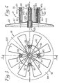
- a transversal tubular portion 23 is connected, preferably by welding, at the vertices of the bent zones of the said lateral arms 22 (22a), the ends of which portion are slightly projected from the sides of the structure of the base element 2.
- transversal tubular portion 23 is provided near its ends with two diametrically opposite through holes 231, in which the coupling teeth 85 of the studs 8 of the wheels 7 will be engaged (see also fig. 15), in a manner which will be hereinafter described;
- a cylindrical bush 32 is formed in correspondence of the vertex zone of the arms 31 referred to and is provided with two longitudinal grooves 321, whose function will be described afterwards.
- two hollow cylindrical bodies 33 which are closed in their inner end and present an inner diameter which is equal to the outer diameter of the tubular ends of the lateral arms of either the handle 1 or the base 2, which engage with them in a manner which will be next described.
- a transversal relief 37 is provided on the bottom side 35 referred to to permit the above specified two opposite grooves 122 to be engaged therewith, which grooves in turn are provided at the free ends of either the lateral arms 12 of the handle 1 or the portions 22a of the base element 2, so permitting transversal movements of the said free ends to be prevented;
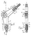
- An annular relief 42 is provided at one end of the first stud 4 and is projecting for a determinate portion therefrom, wherein the annular relief 42 terminates with a first male part 43 of a quickly connecting joint and the other end of the same terminates, on the contrary, with an outer threaded portion 44 in which a correspondent inner threaded ring nut 45 is engaged, from which a second male part 46 always of a quickly connecting joint, equal to the previous one, is extended.
- two tongues 47 which are complementary to said longitudinal grooves 321 in which they may be engaged, are provided near the threaded portion 44, in such a manner that the stud 4 is prevented from being rotated into the cylindrical bush 32, as it will be described later;
- two tongues 57 which are complementary to the longitudinal grooves 624 are provided near the resilient tongues 52 and permit them, as it will be hereinafter described, to be engaged with the same longitudinal grooves 624 so as to connect together both the spool 6 and the crank 54, which actuates the same spool.
- the arm 541 of the crank 54 is extended radially from the other end of the stud 5, from which arm the hollow cylindrical body 542 is extended, at the end thereof, which body constitutes the journal for the relative handle 55 thereof.
- this journal terminates at its free end with a plurality of resilient tongues 543, provided with outwardly projecting teeth 544 at the respective free end thereof.
- the handle 55 is constituted by a tubular cylindrical body 551 having a raised edge 552 at its terminal portion situated near the arm 541, wherein the tubular cylindrical body 551 is provided with an inner annular relief 553 near its other end.
- two diametrically and simmetrically opposite circular shells 63 are extended from the surface of the discoidal body 621 which is comprised inside the spool, when the latter is assembled as described later, which shells costitute a half of the spool drum obtained in a manner which will be hereinafter described.
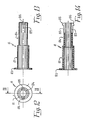
- Such circular shells 63 are each provided with a portion of cylindrical surface 64 extending about 1/4 of the correspondent circumference, whose lateral edges are provided with tubular cylindrical elements 65, which are disposed in the inner side thereof and terminate at their free ends with two male parts 66, the one, and two female parts 67 of snap connecting elements, the other one.
- Each of the two male parts 66 is constituted by a short tubular portion 661, extending from the free ends of the correspondent tubular cylindrical elements 65 and provided in its inner side with an annular relief 662, followed by two diametrically opposite openings 663.
- each of the two female parts 67 is constituted by two resilient tongues 671 projecting from an inner transversal element 672 and terminating near the free ends of the correspondent tubular cylindrical elements 65, wherein the respective parts of the tongues referred to are each provided with a tooth 673 able to be engaged with the inner side of a respective annular relief 662 of the correspondent male part, so positioning it in correspondence of the openings 663;
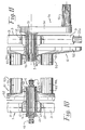
- Such a stud 8 is constituted by a cylindrical body comprising a first portion 81 forming the effective stud of the wheel 7 and provided at its one end with a projected annular part 83, as well as with a second cylindrical portion 84 extended therefrom at its other end, which portion has an outer diameter equal to the inner diameter of the transversal tubular portion 23, in which it will be introduced as described later.
- the free end of the second cylindrical portion 84 is provided with longitudinal notches which generate a couple of diametrically opposite resilient tongues 85, which are provided at their respective free ends with correspondent teeth 86, which are externally protruding therefrom and act for being engaged, as described, within the holes 231 provided on the transversal tubular portion 23.
- the peculiar shaping of the single components thereof is such as to permit that the most part of the same components carries out double functions, which fact permits a reduction of the means foreseen for their manufacture to be obtained.
- this reduction is related to the molds; in fact, the wheels 7 and the relevant studs 8 thereof, the half-spools 61 and the lateral elements 3 are all symmetric elements which are disposed in an opposite symmetrical relationship each other during the cart assembling.
- two half-spools 61 are taken and disposed in an opposed position each other, with the flanges 62 situated on the outside thereof and in such a manner that the respective snap connecting elements result to be positioned with the male parts 66 opposed to the correspondent female parts 67.
- these male and female parts are reciprocally interconnected until the teeth 673, provided on the ends of the resilient tongues 671 of the female parts 67, as they have just got over the respective annular reliefs 662 provided on the inner side of the tubular portions 661 of the male parts 66, are engaged against the inner edge of the annular reliefs 662 so ensuring to obtain a reciprocal connection of the two half-spools and consequently the assembling of the whole spool 6.
- the support structure of the so obtained spool 6 is assembled by inserting, into the hollow cylindrical bodies 33 of two lateral elements 3 which have been disposed in a reciprocal opposite relationship, the ends of the lateral arms 12 of the handle 1, at the one side, and the ends of the lateral arms 22 of the base element 2, at the other side thereof.
- the wheels 7 are assembled simply by inserting a stud 8 into the hole of the respective cylindrical bush 73 and then by inserting the second cylindrical portion 84 of the same stud in a correspondent end of the transversal tubular portion 23, which is fixed onto the base element 2 as already described, until the teeth 86 of this stud penetrate into the correspondent holes 231 provided on such end of the transversal tubular portion 23.
- connection of the stud 8 is ensured and therefore also the wheel 7 is fixed, as it is supported by such a stud end retained between the edge of the end of the transversal tubular portion 23 and the projected annular part 73, which results to be disposed on the outer end portion of the stud 8.
- the spool 6 is assembled to the support structure referred to simply by inserting the first stud 4 into the correspondent cylindrical bush 32 of the two lateral elements 3, as well as into the correspondent cylindrical bush 623 of the lateral flanges 62 of the same spool 6, at the one side thereof, and the second stud 5 into the same components at the other side thereof.
- the first stud 4 is inserted, at the beginning, from the inner side of the spool 6 into the relevant cylindrical bush 623 and then into the cylindrical bush 32 of the correspondent lateral element 3, in such a manner as the tongues 47 of the same penetrate into the relative longitudinal grooves 321, which are provided within the cylindrical bush 32 as already described.
- the relative inner threaded ring nut 45 is screwed onto the outer threaded portion 44, which is projected from the lateral element 3, so as the first stud 4 supports a lateral element 3 with the correspondent flange 62, which are so reciprocally fixed and result to be comprised and retained between the annular relief 42, provided on the inner end of this stud, and the threaded ring nut 45.
- the stud 5 is simply inserted, at the beginning into the cylindrical bush 32 of the other lateral element 3 and then into the cylindrical bush 623 of the correspondent lateral flange 62 of the spool 6, in which the respective tongues 57 penetrate into the correspondent longitudinal grooves 624 of the relative half-spool 61.
- the spool 6 results to be supported at both sides and the crank 54 may drive it in rotation, as the same is connected to said spool by means of the connection constituted by the tongues 57 and the longitudinal grooves 624.
- the teeth 53 provided at the ends of the resilient tongues 52 will push the latter inwardly, while passing through the cylindrical bushes 32 and 623 and may spread themselves, just after they have got over the inner edge of the cylindrical bush 623, so that these teeth will engage themselves with the inner edge of the cylindrical bush 623, so preventing the latter from being extracted therefrom.
- the hose winding cart referred to is completely assembled and may be always not only assembled but also disassembled in a very simple and easy manner, without the need of any tool, as it has been clearly set forth.
- This cart permits various advantages to be obtained.
- the simplicity of the assembling and disassembling system thereof allows its components to be packed within small-sized boxes, which fact results to be useful as much as ever during both the packaging and the transport of the same components.
Landscapes
- Handcart (AREA)
- Storing, Repeated Paying-Out, And Re-Storing Of Elongated Articles (AREA)
- Storage Of Web-Like Or Filamentary Materials (AREA)
- Catching Or Destruction (AREA)
- Forklifts And Lifting Vehicles (AREA)
Claims (3)
- Schlauchrolle mit einem Griffteil (1) und einem Gestellteil (2), beide vorzugsweise aus zweckmäßig gestaltetem Metallrohr bestehend und gegenseitig durch ein Paar Seitenteile (3) miteinander verbunden, die so gestaltet sind, daß der erste Seitenteil einen ersten, mit zum Anschluß von Schläuchen vorgesehenen Anschlußstücken (43, 46) versehenen Stutzen (4) und der zweite Seitenteil einen zweiten, mit einer Kurbel (54) versehenen Stutzen (5) aufnehmen können, wobei solche Stutzen (4, 5) eine zum Aufwickeln von entsprechenden Schlauchlängen vorgesehene Trommel (6) an ihren inneren Enden tragen und solcher Gestellteil (2) ferner mit zwei Seitenrädern (7) versehen ist, dadurch gekennzeichnet, daß sämtliche Bauteile der Schlauchrolle mit Ausnahme vom Griffteil (1) und vom Gestellteil (2) aus Kunststoff sind, und daß solches Paar Seitenteile (3) gleichförmig gestaltet sind, sowie daß solche Trommel (6) aus zwei ebenfalls gleichförmig gestalteten Halbtrommeln (61), wobei der genannte erste Stutzen (4) so von der entsprechenden Halbtrommel (61) getrennt ist, daß die ganze Trommel (6) frei um den Stutzen drehen kann, wobei sämtliche Bauteile, mit Ausnahme des genannten ersten Stutzens (4), auch durch einfaches Druckfügen mit Hilfe von zweckentsprechenden, aus elastisch verformbaren Fügemitteln bestehenden Verbindungsmitteln zusammengebaut und miteinander verbunden werden können und solche elastisch verformbare Fügemittel auf einigen Bauteilen vorgesehen und so gestaltet sind, daß sie durch Druckfügen in entsprechenden Anschlußmitteln auf den damit zu verbindenden Bauteilen eingeschnappt werden können, wobei solche Verbindungsmittel durch zweckentsprechende Ausnehmungen erreicht und zum Zerlegen des Gerätes oder zum Herausnehmen von Teilen davon ohne Verwendung von Werkzeugen abtrennbar sind.
- Schlauchrolle nach Anspruch 1, dadurch gekennzeichnet, daß jede der genannten Halbtrommeln (61) aus einem scheibenförmigen Körper (62) besteht, aus welchem sich zwei diametral und symmetrisch entgegengesetzte Kreisschalen (63) erstrecken, wobei die genannten Kreisschalen (63) mit einem Teil zylindrischer Mantelfläche (64) versehen sind, dessen Seitenränder mit zylindrischen, mit feder- bzw. nutähnlichen Schnappverbindungsmitteln (66, 67) an ihren freien Enden endenden Rohrelementen (65) versehen sind.
- Schlauchrolle nach Anspruch 1 oder 2, dadurch gekennzeichnet, daß jedes Seitenrad (7) mit einem Querrohrteil (23) des Gestellteils (2) mit Hilfe eines Stutzens (8) verbunden ist, wobei solcher Stutzen einen ersten Teil (81), der den tatsächlichen Stutzen des Rades bildet, und einen zweiten zylindrichen Teil (84), der zum Einstecken in das entsprechende Hohlende des genannten Querrohrteils (23) vorgesehen ist, ausweist.
Priority Applications (1)
| Application Number | Priority Date | Filing Date | Title |
|---|---|---|---|
| AT87105970T ATE55756T1 (de) | 1986-05-02 | 1987-04-23 | Schlauchwickelkarre. |
Applications Claiming Priority (2)
| Application Number | Priority Date | Filing Date | Title |
|---|---|---|---|
| IT45723/86A IT1204220B (it) | 1986-05-02 | 1986-05-02 | Carrello avvolgitubo |
| IT4572386 | 1986-05-02 |
Publications (3)
| Publication Number | Publication Date |
|---|---|
| EP0243884A1 EP0243884A1 (de) | 1987-11-04 |
| EP0243884B1 EP0243884B1 (de) | 1990-08-22 |
| EP0243884B2 true EP0243884B2 (de) | 1995-12-06 |
Family
ID=11257721
Family Applications (1)
| Application Number | Title | Priority Date | Filing Date |
|---|---|---|---|
| EP87105970A Expired - Lifetime EP0243884B2 (de) | 1986-05-02 | 1987-04-23 | Schlauchwickelkarre |
Country Status (6)
| Country | Link |
|---|---|
| US (1) | US4768546A (de) |
| EP (1) | EP0243884B2 (de) |
| AT (1) | ATE55756T1 (de) |
| DE (1) | DE3764393D1 (de) |
| ES (1) | ES2017663T5 (de) |
| IT (1) | IT1204220B (de) |
Families Citing this family (56)
| Publication number | Priority date | Publication date | Assignee | Title |
|---|---|---|---|---|
| USD303446S (en) | 1987-08-12 | 1989-09-12 | Suncast Corporation | Portable hose cart |
| GB8902658D0 (en) * | 1989-02-07 | 1989-03-30 | Briggs Irrigation Uk Ltd | Equipment handler |
| US5007598A (en) * | 1989-10-25 | 1991-04-16 | O. Ames Co. | Hose reel assembly |
| US5046520A (en) * | 1990-02-05 | 1991-09-10 | Suncast Corporation | Portable hose cart |
| USD323916S (en) | 1990-03-14 | 1992-02-11 | Suncast Corporation | Hose cart with tray |
| USD321123S (en) | 1990-04-12 | 1991-10-29 | Hunter-Melnor, Inc. | Hose reel cart |
| USD330506S (en) | 1990-07-11 | 1992-10-27 | Gardena Kress + Kastner Gmbh | Hose Reel |
| USD330847S (en) | 1990-07-11 | 1992-11-10 | Gardena Kress+Kastner Gmbh | Hose reel cart |
| USD328173S (en) | 1990-07-13 | 1992-07-21 | The Specialty Mfg. Co. | Garden hose reel caddy |
| US5056553A (en) * | 1990-08-07 | 1991-10-15 | Suncast Corporation | Portable hose cart |
| USD326549S (en) | 1990-08-07 | 1992-05-26 | Suncast Corporation | Hose cart |
| US5179972A (en) * | 1991-02-21 | 1993-01-19 | Eley John H | Hose reel |
| US5109882A (en) * | 1991-02-21 | 1992-05-05 | Eley John H | Hose reel |
| IT1251033B (it) * | 1991-07-31 | 1995-05-02 | Claber Spa | Fiancata di sostegno per tamburo per dispositivo di avvolgimento per tubo flessibile |
| USD349039S (en) | 1992-05-19 | 1994-07-26 | Melnor Inc. | Hose reel |
| USD343710S (en) | 1992-06-15 | 1994-01-25 | Claber S.P.A. | Hose cart |
| USD352149S (en) | 1993-05-20 | 1994-11-01 | The Specialty Mfg. Co. | Portable hose reel caddy |
| US5381981A (en) * | 1993-05-20 | 1995-01-17 | The Specialty Mfg. Co. | Garden hose reel |
| US5425391A (en) * | 1994-09-12 | 1995-06-20 | Suncast Corporation | Stackable hose reel cart |
| US5462298A (en) * | 1994-12-07 | 1995-10-31 | Bodine; Daryl L. | Water hose cart |
| US5520212A (en) * | 1995-04-04 | 1996-05-28 | Williams; Ray F. | Self winding hose reel |
| US5657789A (en) * | 1995-08-11 | 1997-08-19 | Suncast Corporation | Wall mount stackable hose reel |
| US5797424A (en) * | 1995-08-11 | 1998-08-25 | Suncast Corporation | Hose reel |
| USD392080S (en) | 1996-03-05 | 1998-03-10 | Suncast Corporation | Industrial hose cart |
| US5758685A (en) * | 1996-03-05 | 1998-06-02 | Suncast Corporation | Industrial hose cart |
| US5934598A (en) * | 1996-08-23 | 1999-08-10 | Alert Stamping & Mfg. Co., Inc. | Manually operated cord storage reel |
| DE29723788U1 (de) * | 1997-03-14 | 1999-03-25 | Gloria-Werke H. Schulte-Frankenfeld Gmbh & Co, 59329 Wadersloh | Schlauchhaspel für Schlauchwagen oder -träger |
| IT237643Y1 (it) * | 1997-07-07 | 2000-09-13 | Claber Spa | Tamburo per carrelli avvolgitori per tubi flessibili perirrigazione |
| IT243437Y1 (it) * | 1997-10-23 | 2002-03-04 | Uniflex Utiltime Spa | Carrello avvolgitore di tubo per irrigazione |
| US5988552A (en) * | 1998-11-12 | 1999-11-23 | Suncast Corporation | Portable hose reel cart having a folding handle |
| US7252193B1 (en) | 2003-05-07 | 2007-08-07 | John Gordon Lewis | Storage |
| US6978960B2 (en) * | 2003-10-31 | 2005-12-27 | Schaller James M | Hose reel with integral hub assembly |
| US6932106B1 (en) * | 2004-11-19 | 2005-08-23 | King-Yuan Wang | Hose reel |
| WO2006075137A2 (en) * | 2005-01-12 | 2006-07-20 | Hozelock Limited | Cased hose reels |
| JP4687323B2 (ja) * | 2005-08-12 | 2011-05-25 | オムロンヘルスケア株式会社 | 血圧計測装置 |
| JP4876587B2 (ja) * | 2006-01-13 | 2012-02-15 | オムロンヘルスケア株式会社 | 血圧計測装置 |
| US20080023579A1 (en) * | 2006-07-27 | 2008-01-31 | Alemite Llc | Modular reel assembly |
| USD584937S1 (en) | 2007-01-31 | 2009-01-20 | Alert Safety Lite Products Co., Inc. | Cord reel |
| WO2009016615A2 (en) * | 2007-07-30 | 2009-02-05 | Sharona Keren | Conduit reel for dripper irrigation line |
| USD604244S1 (en) | 2007-10-10 | 2009-11-17 | Alert Stamping & Manufacturing Co., Inc. | Cord reel |
| CN101456022B (zh) | 2007-12-10 | 2012-02-29 | 苏州金莱克精密机械有限公司 | 用于高压清洗机卷轮的旋转装置 |
| USD590566S1 (en) * | 2008-07-28 | 2009-04-14 | Ames True Temper, Inc. | Metal cart |
| US9073730B2 (en) * | 2008-10-23 | 2015-07-07 | The Ames Companies, Inc. | Deck box |
| USD604019S1 (en) * | 2009-04-13 | 2009-11-10 | Ames True Temper, Inc. | Hose reel |
| USD604020S1 (en) * | 2009-04-13 | 2009-11-10 | Ames True Temper, Inc. | Hose reel |
| USD604021S1 (en) * | 2009-07-13 | 2009-11-10 | Ames True Temper, Inc. | Hose reel |
| USD646039S1 (en) * | 2010-06-17 | 2011-09-27 | Claber S.P.A. | Hose winding cart |
| ITMI20100205U1 (it) * | 2010-06-17 | 2011-12-18 | Claber Spa | Carrello avvolgitubo a tamburo metallico con manico di manovra ad altezza regolabile. |
| WO2012065642A1 (en) * | 2010-11-17 | 2012-05-24 | Gardena Manufacturing Gmbh | Tube and mounting frame assembly |
| DE202011004378U1 (de) | 2011-03-24 | 2011-06-01 | SILAG Handel AG, 40764 | Schlauchwagen mit Doppelhaspel und Schlauchverbinder |
| US20120255627A1 (en) * | 2011-04-08 | 2012-10-11 | Ames True Temper, Inc. | Hose reel assembly having limited hardware |
| US20120255625A1 (en) * | 2011-04-08 | 2012-10-11 | Ames True Temper, Inc. | Hose reel having a horizontally split frame |
| US8851413B2 (en) | 2012-11-02 | 2014-10-07 | Suncast Technologies, Llc | Reel assembly |
| US9126612B2 (en) * | 2013-08-22 | 2015-09-08 | Hsiu-Man Yu Chen | Cable reel trolley |
| ITMO20140025U1 (it) * | 2014-07-21 | 2016-01-21 | Gf Srl | Dispositivo di supporto per un tubo |
| US10035531B2 (en) | 2015-11-20 | 2018-07-31 | Bridging Gaps, LLC | Cart |
Family Cites Families (6)
| Publication number | Priority date | Publication date | Assignee | Title |
|---|---|---|---|---|
| US3977429A (en) * | 1972-12-15 | 1976-08-31 | Stevenson James S | Hose reel assembly |
| US4137939A (en) * | 1977-10-11 | 1979-02-06 | Melnor Industries | Hose reel cart |
| AT365007B (de) * | 1979-03-29 | 1981-12-10 | Contact Gmbh | Kabelaufroller |
| US4512361A (en) * | 1982-11-29 | 1985-04-23 | Suncast Corporation | Hose storage apparatus |
| US4506698A (en) * | 1983-07-07 | 1985-03-26 | Suncast Corporation | Garden hose storage apparatus |
| DE3324855A1 (de) * | 1983-07-09 | 1985-01-24 | Rehau Plastiks Ag + Co, 8673 Rehau | Wickeleinrichtung fuer wickelbares gut |
-
1986
- 1986-05-02 IT IT45723/86A patent/IT1204220B/it active
-
1987
- 1987-04-20 US US07/040,474 patent/US4768546A/en not_active Expired - Lifetime
- 1987-04-23 EP EP87105970A patent/EP0243884B2/de not_active Expired - Lifetime
- 1987-04-23 ES ES87105970T patent/ES2017663T5/es not_active Expired - Lifetime
- 1987-04-23 AT AT87105970T patent/ATE55756T1/de not_active IP Right Cessation
- 1987-04-23 DE DE8787105970T patent/DE3764393D1/de not_active Expired - Fee Related
Also Published As
| Publication number | Publication date |
|---|---|
| DE3764393D1 (de) | 1990-09-27 |
| EP0243884B1 (de) | 1990-08-22 |
| EP0243884A1 (de) | 1987-11-04 |
| ATE55756T1 (de) | 1990-09-15 |
| ES2017663B3 (es) | 1991-03-01 |
| IT8645723A0 (it) | 1986-05-02 |
| IT1204220B (it) | 1989-03-01 |
| ES2017663T5 (es) | 1996-04-16 |
| US4768546A (en) | 1988-09-06 |
Similar Documents
| Publication | Publication Date | Title |
|---|---|---|
| EP0243884B2 (de) | Schlauchwickelkarre | |
| US5007598A (en) | Hose reel assembly | |
| US5127762A (en) | Connector assembly | |
| US4027987A (en) | Joining device for connecting tubes | |
| US4706906A (en) | Three-arm hub joint for tubular structures specifically for hose racks and hose carts | |
| US5178585A (en) | Chain with easily adjustable number of links | |
| US3940085A (en) | Collapsible reel | |
| US5028187A (en) | Security fastener including integral plug body and socket body | |
| EP0525868A1 (de) | Trommelstützwange für eine Schlauchaufwickelvorrichtung | |
| US5116053A (en) | Puzzle | |
| US3977040A (en) | Castor | |
| US5136782A (en) | Appliance for scrub clearance, grass cutting or the like, with devices for lengthening the cutting line and coupling devices | |
| CA2335682A1 (en) | Salt platform with hub having locking element | |
| JPH0365196B2 (de) | ||
| US5726732A (en) | Structure for coupling some selected parts of a pair of eyeglasses | |
| US4076429A (en) | Convertible tube connecting system | |
| US4007650A (en) | Garden hose coupling tool | |
| US3744329A (en) | Modular pulley capable of being assembled to various desired lengths and automatic belt-steering pulley assembly | |
| EP0857505A1 (de) | Motor für Spielzeugbausystem | |
| US4089485A (en) | Reel for the storage of filamentary material | |
| US4344655A (en) | Two-part moulded wheel made of plastic material for children's vehicle | |
| US4090737A (en) | Agricultural spoke wheel | |
| US4039233A (en) | Connection apparatus for multipiece bearing race | |
| EP0911292A1 (de) | Wickelwagen für Gartenschlauch | |
| JPS5812803A (ja) | 双輪キヤスタ |
Legal Events
| Date | Code | Title | Description |
|---|---|---|---|
| PUAI | Public reference made under article 153(3) epc to a published international application that has entered the european phase |
Free format text: ORIGINAL CODE: 0009012 |
|
| AK | Designated contracting states |
Kind code of ref document: A1 Designated state(s): AT DE ES FR GB IT NL SE |
|
| 17P | Request for examination filed |
Effective date: 19871022 |
|
| 17Q | First examination report despatched |
Effective date: 19881031 |
|
| GRAA | (expected) grant |
Free format text: ORIGINAL CODE: 0009210 |
|
| AK | Designated contracting states |
Kind code of ref document: B1 Designated state(s): AT DE ES FR GB IT NL SE |
|
| PG25 | Lapsed in a contracting state [announced via postgrant information from national office to epo] |
Ref country code: SE Free format text: THE PATENT HAS BEEN ANNULLED BY A DECISION OF A NATIONAL AUTHORITY Effective date: 19900822 Ref country code: NL Effective date: 19900822 Ref country code: AT Effective date: 19900822 |
|
| REF | Corresponds to: |
Ref document number: 55756 Country of ref document: AT Date of ref document: 19900915 Kind code of ref document: T |
|
| ITF | It: translation for a ep patent filed | ||
| REF | Corresponds to: |
Ref document number: 3764393 Country of ref document: DE Date of ref document: 19900927 |
|
| ET | Fr: translation filed | ||
| NLV1 | Nl: lapsed or annulled due to failure to fulfill the requirements of art. 29p and 29m of the patents act | ||
| PGFP | Annual fee paid to national office [announced via postgrant information from national office to epo] |
Ref country code: SE Payment date: 19910320 Year of fee payment: 5 |
|
| ITTA | It: last paid annual fee | ||
| PLBI | Opposition filed |
Free format text: ORIGINAL CODE: 0009260 |
|
| 26 | Opposition filed |
Opponent name: GARDENA, KRESS & KASTNER GMBH Effective date: 19910511 |
|
| PLAB | Opposition data, opponent's data or that of the opponent's representative modified |
Free format text: ORIGINAL CODE: 0009299OPPO |
|
| R26 | Opposition filed (corrected) |
Opponent name: GARDENA, KRESS & KASTNER GMBH Effective date: 19910511 |
|
| PUAH | Patent maintained in amended form |
Free format text: ORIGINAL CODE: 0009272 |
|
| STAA | Information on the status of an ep patent application or granted ep patent |
Free format text: STATUS: PATENT MAINTAINED AS AMENDED |
|
| 27A | Patent maintained in amended form |
Effective date: 19951206 |
|
| AK | Designated contracting states |
Kind code of ref document: B2 Designated state(s): AT DE ES FR GB IT NL SE |
|
| ITF | It: translation for a ep patent filed | ||
| ET3 | Fr: translation filed ** decision concerning opposition | ||
| REG | Reference to a national code |
Ref country code: ES Ref legal event code: DC2A Kind code of ref document: T5 Effective date: 19960416 |
|
| REG | Reference to a national code |
Ref country code: GB Ref legal event code: IF02 |
|
| PGFP | Annual fee paid to national office [announced via postgrant information from national office to epo] |
Ref country code: FR Payment date: 20030311 Year of fee payment: 18 |
|
| PGFP | Annual fee paid to national office [announced via postgrant information from national office to epo] |
Ref country code: GB Payment date: 20040316 Year of fee payment: 18 |
|
| PGFP | Annual fee paid to national office [announced via postgrant information from national office to epo] |
Ref country code: DE Payment date: 20040330 Year of fee payment: 18 |
|
| PGFP | Annual fee paid to national office [announced via postgrant information from national office to epo] |
Ref country code: ES Payment date: 20040407 Year of fee payment: 18 |
|
| PG25 | Lapsed in a contracting state [announced via postgrant information from national office to epo] |
Ref country code: IT Free format text: LAPSE BECAUSE OF NON-PAYMENT OF DUE FEES Effective date: 20050423 Ref country code: GB Free format text: LAPSE BECAUSE OF NON-PAYMENT OF DUE FEES Effective date: 20050423 |
|
| PG25 | Lapsed in a contracting state [announced via postgrant information from national office to epo] |
Ref country code: ES Free format text: LAPSE BECAUSE OF NON-PAYMENT OF DUE FEES Effective date: 20050425 |
|
| PG25 | Lapsed in a contracting state [announced via postgrant information from national office to epo] |
Ref country code: DE Free format text: LAPSE BECAUSE OF NON-PAYMENT OF DUE FEES Effective date: 20051101 |
|
| GBPC | Gb: european patent ceased through non-payment of renewal fee |
Effective date: 20050423 |
|
| PG25 | Lapsed in a contracting state [announced via postgrant information from national office to epo] |
Ref country code: FR Free format text: LAPSE BECAUSE OF NON-PAYMENT OF DUE FEES Effective date: 20051230 |
|
| REG | Reference to a national code |
Ref country code: FR Ref legal event code: ST Effective date: 20051230 |
|
| REG | Reference to a national code |
Ref country code: ES Ref legal event code: FD2A Effective date: 20050425 |