EP0243825B1 - Wire incrusted with abrasive grain and method for producing the same - Google Patents
Wire incrusted with abrasive grain and method for producing the same Download PDFInfo
- Publication number
- EP0243825B1 EP0243825B1 EP19870105714 EP87105714A EP0243825B1 EP 0243825 B1 EP0243825 B1 EP 0243825B1 EP 19870105714 EP19870105714 EP 19870105714 EP 87105714 A EP87105714 A EP 87105714A EP 0243825 B1 EP0243825 B1 EP 0243825B1
- Authority
- EP
- European Patent Office
- Prior art keywords
- metallic
- wire
- pipe
- powder
- gap
- Prior art date
- Legal status (The legal status is an assumption and is not a legal conclusion. Google has not performed a legal analysis and makes no representation as to the accuracy of the status listed.)
- Expired - Lifetime
Links
Images


Classifications
-
- B—PERFORMING OPERATIONS; TRANSPORTING
- B22—CASTING; POWDER METALLURGY
- B22F—WORKING METALLIC POWDER; MANUFACTURE OF ARTICLES FROM METALLIC POWDER; MAKING METALLIC POWDER; APPARATUS OR DEVICES SPECIALLY ADAPTED FOR METALLIC POWDER
- B22F7/00—Manufacture of composite layers, workpieces, or articles, comprising metallic powder, by sintering the powder, with or without compacting wherein at least one part is obtained by sintering or compression
- B22F7/06—Manufacture of composite layers, workpieces, or articles, comprising metallic powder, by sintering the powder, with or without compacting wherein at least one part is obtained by sintering or compression of composite workpieces or articles from parts, e.g. to form tipped tools
- B22F7/08—Manufacture of composite layers, workpieces, or articles, comprising metallic powder, by sintering the powder, with or without compacting wherein at least one part is obtained by sintering or compression of composite workpieces or articles from parts, e.g. to form tipped tools with one or more parts not made from powder
-
- B—PERFORMING OPERATIONS; TRANSPORTING
- B22—CASTING; POWDER METALLURGY
- B22F—WORKING METALLIC POWDER; MANUFACTURE OF ARTICLES FROM METALLIC POWDER; MAKING METALLIC POWDER; APPARATUS OR DEVICES SPECIALLY ADAPTED FOR METALLIC POWDER
- B22F5/00—Manufacture of workpieces or articles from metallic powder characterised by the special shape of the product
- B22F5/12—Manufacture of workpieces or articles from metallic powder characterised by the special shape of the product of wires
-
- B—PERFORMING OPERATIONS; TRANSPORTING
- B23—MACHINE TOOLS; METAL-WORKING NOT OTHERWISE PROVIDED FOR
- B23D—PLANING; SLOTTING; SHEARING; BROACHING; SAWING; FILING; SCRAPING; LIKE OPERATIONS FOR WORKING METAL BY REMOVING MATERIAL, NOT OTHERWISE PROVIDED FOR
- B23D61/00—Tools for sawing machines or sawing devices; Clamping devices for these tools
- B23D61/18—Sawing tools of special type, e.g. wire saw strands, saw blades or saw wire equipped with diamonds or other abrasive particles in selected individual positions
- B23D61/185—Saw wires; Saw cables; Twisted saw strips
-
- B—PERFORMING OPERATIONS; TRANSPORTING
- B23—MACHINE TOOLS; METAL-WORKING NOT OTHERWISE PROVIDED FOR
- B23D—PLANING; SLOTTING; SHEARING; BROACHING; SAWING; FILING; SCRAPING; LIKE OPERATIONS FOR WORKING METAL BY REMOVING MATERIAL, NOT OTHERWISE PROVIDED FOR
- B23D65/00—Making tools for sawing machines or sawing devices for use in cutting any kind of material
-
- B—PERFORMING OPERATIONS; TRANSPORTING
- B24—GRINDING; POLISHING
- B24D—TOOLS FOR GRINDING, BUFFING OR SHARPENING
- B24D18/00—Manufacture of grinding tools or other grinding devices, e.g. wheels, not otherwise provided for
-
- B—PERFORMING OPERATIONS; TRANSPORTING
- B22—CASTING; POWDER METALLURGY
- B22F—WORKING METALLIC POWDER; MANUFACTURE OF ARTICLES FROM METALLIC POWDER; MAKING METALLIC POWDER; APPARATUS OR DEVICES SPECIALLY ADAPTED FOR METALLIC POWDER
- B22F5/00—Manufacture of workpieces or articles from metallic powder characterised by the special shape of the product
- B22F2005/001—Cutting tools, earth boring or grinding tool other than table ware
-
- Y—GENERAL TAGGING OF NEW TECHNOLOGICAL DEVELOPMENTS; GENERAL TAGGING OF CROSS-SECTIONAL TECHNOLOGIES SPANNING OVER SEVERAL SECTIONS OF THE IPC; TECHNICAL SUBJECTS COVERED BY FORMER USPC CROSS-REFERENCE ART COLLECTIONS [XRACs] AND DIGESTS
- Y10—TECHNICAL SUBJECTS COVERED BY FORMER USPC
- Y10T—TECHNICAL SUBJECTS COVERED BY FORMER US CLASSIFICATION
- Y10T29/00—Metal working
- Y10T29/49—Method of mechanical manufacture
- Y10T29/4998—Combined manufacture including applying or shaping of fluent material
- Y10T29/49988—Metal casting
- Y10T29/49989—Followed by cutting or removing material
-
- Y—GENERAL TAGGING OF NEW TECHNOLOGICAL DEVELOPMENTS; GENERAL TAGGING OF CROSS-SECTIONAL TECHNOLOGIES SPANNING OVER SEVERAL SECTIONS OF THE IPC; TECHNICAL SUBJECTS COVERED BY FORMER USPC CROSS-REFERENCE ART COLLECTIONS [XRACs] AND DIGESTS
- Y10—TECHNICAL SUBJECTS COVERED BY FORMER USPC
- Y10T—TECHNICAL SUBJECTS COVERED BY FORMER US CLASSIFICATION
- Y10T83/00—Cutting
- Y10T83/929—Tool or tool with support
- Y10T83/9292—Wire tool
Definitions
- the present invention relates to a method for producing a metallic wire for cutting, grinding or chamfering processing of hard materials, in particular, to a metallic wire for cutting and grinding processing having abrasive grains uniformly and firmly arranged and retained in the surface layer.
- a wire with high tensile strength a so-called saw wire is also known for these purposes.
- processing such as cutting or the like is carried out under the condition that free abrasive grains are existing between the wire and a material to be processed and grinding actions are performed only by frictional force, causing a problem of insufficient efficiency.
- electro-spark machining method For the cutting, a so-called electro-spark machining method is known in which a high voltage is applied between the wire and a material to be cut to cut the material by discharge between the both.
- the method however, has problems in that the material to be cut is limited only to electroconductive materials.
- double-structure wires such as wires coated with copper or aluminum are now generally used. If such an abrasive grain/steel structure wire is taken as a mere double-structure steel wire and a conventional manufacturing technology for double-structure wires is applied to produce the abrasive grain/steel structure wire, a die for wire drawing is markedly attacked and abraded by the abrasive grains, for example, in a wire drawing process, so that it is practically impossible to apply the conventional wire drawing procsing technology to the production of the above-mentioned abrasive grain/steel structure wire.
- US-A-4055700 discloses a wire having a thin wire core and integral therewith, hard cutting crystals with cutting edges projecting irregularly from the wire core surface.
- abrasive grains are fixed on a thin wire core by vapor phase deposition.
- US-A-3168399 discloses a method of producing a tube of circular cross section consisting of a sintered metal, which does not comprise any further components but metal.
- the wire incrusted with abrasive grains produced according to the present invention is obtained by the following steps. First, a metallic rod made of a metallic material is inserted into the central part of a metallic pipe 1, being made from the same or a different material than the metallic rod, with a gap S formed between said rod and said metallic pipe to obtain a cylindrical metallic body A having desired dimensions, then the gap S is filled with a mixture D containing metallic powder 4 and abrasive grains 3 having a Mohs hardness of 6 or more as the main component, and then both ends of said gap S are hermetically sealed.
- abrasive grains mixed with the metallic powder are not limited to a diamond powder and CBN (cubic boron nitride) powder, but ceramics, superhard alloys, glass, and the like having a Mohs hardness of 6 or more can be used as the abrasive grains.
- ceramics such as alumina (Al2O3) or silicon nitride (Si3N4) are suitable.
- the Mohs hardness is an emperical scale to determine the hardness of ores by comparison with ten kinds of ores providing standards.
- the standard ores in an order of the softest ore (having a scale of 1) to the hardest one (having a scale of 10) are talc, gypsum, calcite, fluorite, apatite, orthoclase, quartz, topaz, corundum, and diamond.
- Abrasive grains used in the method of the invention usually have a hardness larger than that of the orthoclase standard having a hardness of 6. Abrasive grains having a hardness lower than the orthoclase standard are not appropriate in respect of the performance of the obtained wire incrusted with abrasive grains.
- the above-mentioned abrasive grains are usually mixed with a metallic powder and the mixture in a powdered state is filled into a gap in the above-mentioned metallic body but it is effective to granulate the above-mentioned mixture and to fill the resulting granules into the gap for the purpose of preventing the metallic powder and the abrasive grains from separation or segregation caused by a difference in gravity between both.
- a pipe shaped metal B may be tightly fitted around the metallic rod 2 inserted into the central part of the metallic pipe 1 with a gap formed between the metal B and the pipe 1 or a thin metallic belt C may be wound around the above-mentioned rod to prevent that in a cold wire drawing process the above-mentioned inserted metallic rod 2 is pierced with abrasive grains and is notched in its central part.
- the method for manufacturing the wire it is easy to form the metallic pipe and the central metallic rod separately into an appropriate size by using components of the same or different kind that fit the use conditions for both.
- the outermost layer of the above-mentioned metallic body is a metallic pipe and a wire draw-working is brought into contact with only the metallic pipe during a wire drawing process, the wire drawing die is not brought into contact with the abrasive grain powder, so that the abrasive grain powder is firmly stuck to the wire.
- the thus obtained wire of desired diameter has an outermost layer only consisting of the metallic pipe, the mixed layer containing abrasive grains is exposed on the outermost surface of the resulting wire if the metallic pipe layer is removed. Accordingly, the wire incrusted with abrasive grains can be quickly and cheaply produced.
- Figs. 1(a) and 1(b) are a plan view and a side sectional view, each showing the structure of a metallic body A having a metallic rod 2 inserted into the central part of a metallic pipe 1 and having a gap between the metallic pipe and the metallic rod filled with a mixture comprising a metallic powder and abrasive grains.
- A shows the metallic body, 1, the outermost metallic pipe, and 2, the metallic rod in the central part of the metallic pipe.
- the metallic rod 2 is inserted into the central part of the metallic pipe 1 with a gap S formed in between, and a mixture of abrasive grains 3 having a Mohs hardness of 6 or more with a metallic powder 4 is filled into the gap S.
- the material of the metallic pipe 1 positioned at the periphery of the metallic body A and of the metallic rod 2 in the central part of the metallic body A carbon steel is generally used but stainless steel, a copper alloy, or the like may also be used according to the use conditions, and the materials of the metallic pipe 1 and the metallic rod 2 may be different from each other.
- the thickness of the metallic pipe 1, the diameter of the metallic rod 2, and the width of the gap between both are each appropriately determined according to the diameter or the final wire, the average grain size of abrasive grains 3 and the mixing ratio of the abrasive grains 3 to the metallic powder 4.
- abrasive grain powder 3 having a Mohs hardness of 6 or more there are specifically, in addition to a diamond powder and a CPN powder, ceramics such as alumina (Al2O3) and silicon nitride (Si3N4), hard metal powder, glass powder, and the like, and they are used in the form of a single compound or of a mixture of two or more compounds.
- ceramics such as alumina (Al2O3) and silicon nitride (Si3N4), hard metal powder, glass powder, and the like, and they are used in the form of a single compound or of a mixture of two or more compounds.
- Ni powder or Ni base alloy powder is generally used but, other than those, Cu powder, Cu base alloy powder, Co powder, Co base alloy powder, and the like which are bond metal powder used for manufacturing of general abrasive grain tools may be used.
- Both ends of gap S of the metallic body A after being filled with the mixed powder D are capped with an appropriate cover material and then welded to hermetically seal the metallic body A. Then hot working such as extrusion or rolling and then a heat treatment such as annealing or patenting is applied and subsequently, cold working is applied to the metallic body A to produce a wire having a desired diameter.
- the diffusion of the metallic powder 4 filled in the gap between the metallic pipe 1 and the central metallic rod 2 into the metallic pipe 1 or into the metallic rod 2 during the hot working is undesirable, it is possible to prevent the diffusion phenomenon by plating the inner surface of the metallic pipe 1 or the outer surface of the metallic rod 2 with copper or the like in advance to form a layer tot prevent the diffusion.
- a pipe-shaped metal B may be tightly fitted around the metallic rod 2 inserted into the central part of the metallic pipe 1 with a gap formed between the metal B and the pipe 1 or a thin metallic belt C may be wound around the rod 2. This is effective to prevent that in a cold working the above-mentioned inserted metallic rod 2 is pierced with abrasive grains and is notched in its central part.
- a wire produced by use of the above-mentioned mixed powder having a non-uniform composition and being segregated shows a marked difference in the density of the exposed abrasive grains at different locations on the wire surface, so that an improper product might result.
- the mixed powder comprising diamond abrasive grains and Ni powder is granulated to prepare a powder comprising spherical granules, which is filled into the gap between the above-mentioned metallic pipe and central metallic rod.
- the diamond abrasive grains separate or segregate from the Ni powder.
- a binder is added as an additive but if a binder such as an organic compound is used, joining between the particles of powder is sometimes hindered by the above-mentioned binder when the above-mentioned metallic body is subjected to a following treatment
- the residual metallic pipe 1 as the outermost layer of the wire is removed by polishing, pickling or the like.
- Fig. 2 shows the thus obtained wire incrusted with abrasive grains having a mixed layer D' exposed on the surface of the drawn central metallic rod 2, the mixed layer D' having the abrasive grains uniformly and firmly retained in the metallic layer 4' consisting of sintered metallic powder.
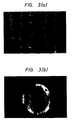
- Fig. 3(a) is a micrograph showing one example of the surface metallic structure of the thus obtained wire.
- a JIS-SS 41 steel material was used for the peripheral metallic pipe 1 and a JIS-SK 7 steel material was used for the central metallic rod 2.
- the outermost diameter of the metallic body A was 70 mm, the thickness of the peripheral metallic pipe was 5 mm, and the width of the gap S was 8 mm.
- Fig. 3(b) is a micrograph showing one example of a metallic structure in the section of the wire.
- the thus obtained wire was dipped for 15 minutes into a hydrochloric acid solution having a concentration of 35% to dissolve and remove the carbon steel material (SS 41) of the metallic pipe which remained as the outermost layer of the wire and then it was neutralized with an alkali solution and washed with water.
- a hydrochloric acid solution having a concentration of 35% to dissolve and remove the carbon steel material (SS 41) of the metallic pipe which remained as the outermost layer of the wire and then it was neutralized with an alkali solution and washed with water.
- Fig. 3(a) is a micrograph showing one example of a metallic structural state of the surface of the thus obtained wire incrusted with diamond abrasive grains. It will be seen that find diamond grains are uniformly and firmly stuck to and embedded into the periphery of the wire.
- a JIS-SS 41 steel material and a JIS-SUS 30 stainless steel material were used for the peripheral metallic pipe 1 and the central metallic rod 2, respectively.
- the outermost diameter of the metallic body A was 70 mm, the thickness of the peripheral metallic pipe was 5 mm and the width of the gap S in the metallic body A was 8 mm.
- CBN grains having an average particle size of 150 ⁇ m were mixed with pure nickel powder in a mixing ratio of 13% by volume of CBN grains to prepare a mixture D. After the gap part of the metallic body A was filled with the mixture D, both ends of the gap part were hermetically sealed.
- the metallic body A was heated at 1050°C for 2 hours and then extruded at an extrusion ratio of 15. Further heat treatment and cold working were repeated to produce a wire having a diameter of 1.0 mm.
- the tensile strength of the wire was 1824037 kPa (183 kg/mm2).
- the wire was dipped into a hydrochloric acid solution having a concentration of 35% to dissolve and remove the outermost carbon steel material (SS 41) of the metallic body A which remained as the outermost layer of the wire and then it was neutralized with an alkali solution and washed with water.
- the thus obtained wire incrusted with abrasive grains was used for cutting and grinding processing of iron based materials and as a result, extremely good cutting and grinding processing could be performed, whereas, with the conventional diamond wires produced by a plating method, the surface diamond grains were intensely abraded owing to the action of the iron of the surface of the worked iron material and processing of the iron material with the wire was difficult.
- a JIS-SS 41 steel material and a JIS-SK 7 steel material were used for the outermost metallic pipe 1 and the central metallic rod 2, respectively.
- the outermost diameter of the metallic body A was 70 mm, the thickness of the outermost metallic pipe was 7 mm, and the width of the gap S in the metallic object A was 7 mm.
- a diamond powder of an average particle size of 30 ⁇ m was mixed with a mixture prepared by mixing 0.5% by weight of carbon with pure nickel powder in a mixing ratio of 15% by volume of diamond powder to produce mixed powder D. After the gap S of the metallic object A was filled with the mixed powder D, both ends of the gap S were hermetically sealed.
- the metallic object A was heated at 1050°C for 2 hours and extruded at an extrusion ratio of 15. Further, heat treatment and cold working were repeated to produce a wire having a diameter of 0.26 mm.
- the tensile strength of the wire was 1755390 kPa (179 kg/mm2).
- the wire was dipped for 5 minutes into a hydrochloric acid solution having a concentration of 35% to dissolve and remove the outermost carbon steel material (SS 41) of the metallic object A which remained is the outermost layer of the wire and then it was neutralized with an alkali solution and washed with water.
- a carbon steel pipe JIS-STK 30
- a piano wire JIS-SWRS 72B
- the outermost diameter of the metallic body A was 20 mm, the thickness of the metallic pipe was 2 mm and the diameter of the metallic rod was 13 mm.
- a fine diamond powder having an average particle size of 30 ⁇ m was used as abrasive grains.
- the diamond powder was mixed with Ni powder in a mixing ratio of 15% by volume of the diamond powder to prepare a mixture and further, 0.5% by weight of camphor as a binder was added to prepare a mixed powder.
- the mixed powder was granulated by a wet spray method to prepare granules, which were than held in a nitrogen atmosphere at 300°C for 1 hour to sublime the camphor.
- a mixture D comprising the granules was produced.
- the tensile strength of the wire was 1765197 kPa (180 kg/mm2).
- Example 3 the outermost layer 1 of the metallic body A was dissolved and removed, and then the resulting wire was neutralized with an aqueous alkali solution and washed with water.
- the wire was used for cutting processing and as a result, good cutting performance comparable to that in Example 3 was obtained.
- a carbon steel material JIS-SS-41) and a carbon steel material (JIS-SK 7) were used for the peripheral metallic pipe 1 and the central metallic rod 2, respectively.
- the outermost diameter of the metallic body A was 70 mm, the thickness of the metallic pipe was 5 mm, and the width of the gap S was 6 mm.
- a pure nickel tube B having an inner diameter of 48 mm and a wall thickness of 2 mm was inserted into the gap S to fit it tightly around the metallic rod 2.
- a diamond powder having an average particle size of 120 ⁇ m was mixed with a mixture prepared by mixing 0.5% by weight of carbon with pure nickel powder in a mixing ratio of 13% by volume of the diamond powder to prepare mixed powder D. After the gap S' between the above-mentioned Ni tube B and the metallic pipe 1 in the metallic body A was filled with the mixed powder D, both ends of the gap S in the metallic object A were hermetically sealed.
- the metallic body A was heated at 1050°C for 2 hours, and then extruded at an extrusion ratio of 15. Further, heat treatment and cold working were repeated to produce a wire having a diamter of 1.0 mm.
- the tensile strength of the wire was 1647517 kPa (168 kg/mm2).
- the structure of the wire was observed on a microphotograph and as a result, it was found that the diamond particles were separated from the central metal rod by the pipe-shaped nickel metal and the central metal rod was not pierced with the diamond particles and was not notched.
- the wire was dipped for 15 minutes into a hydrochloric acid solution having a concentration of 35% to dissolve and remove the outermost metallic pipe of carbon steel (SS 41) of the metallic body A which remained as the outermost layer of the wire. Then, the resulting wire was neutralized with an aqueous alkali solution and washed with water.
- a hydrochloric acid solution having a concentration of 35% to dissolve and remove the outermost metallic pipe of carbon steel (SS 41) of the metallic body A which remained as the outermost layer of the wire.
- the thus obtained wire incrusted with diamond abrasive grains was a wire of long life which had the outer peripheral part uniformly stuck with diamond particles and the inside part not pierced with diamond particles into the center part and not notched.
- a carbon steel pipe JIS-STK 30
- a piano wire JIS-SWRS 72B
- the outermost diameter of the metallic body A was 20 mm, the thickness of the metallic pipe was 2 mm, and the diameter of the metallic rod was 12 mm.
- a thin belt C of pure nickel having a thickness of 0.1 mm was wound densely around the metallic rod 2 to form a nickel belt layer of a thickness of 0.5 mm on the rod 2.
- a gap S' between the nickel belt and the metallic pipe 1 was filled with a mixed powder D prepared by mixing CBN abrasive grains 3 having an average grain size of 30 ⁇ m with pure nickel metal powder in a mixing ratio of 13% by volume of CBN abrasive gains 3, both ends of the gap S ware capped and then were hermetically sealed.
- a heat treatment comprising heating to 950°C and subsequently cooling by air and cold working were applied to the metallic body A seven times repeatedly to produce a wire of a diameter of 0.26 mm.
- the tensile strength of the wire was 1676937 kPa (171 kg/mm2).
- the wire was dipped for 5 minutes into a hydrochloric acid solution having a concentration of 35% to dissolve and remove the outermost carbon steel (STK 30) material of the metallic body A which remained as the outermost layer of the wire.
- STK 30 outermost carbon steel
- the thus obtained wire incrusted with CBN abrasive grains was a wire of markedly long life wherein the central metallic rod was not pierced with CBN abrasive grains and was notched easily and the wire fractured easily, as compared with a wire incrusted with CNB abrasive grains of the same diameter produced by a conventional wire drawing method using none of a pipe-shaped metallic body and a thin metallic belt.
- a JIS-SS 41 steel material and a JIS-SUS 304 stainless steel material were used for the peripheral metallic pipe 1 and the central metallic rod 2, respectively.
- the outermost diameter of the metallic body A was 70 mm, the thickness of the peripheral metallic pipe was 5 mm, and the width of the gap S was 8 mm.
- a mixed powder D prepared by mixing alumina (Al2O3) powder 3 having an average particle size of 150 ⁇ m with pure Ni powder in a mixing ratio of 13% by volume of alumina, both ends of the gap S of the metallic body A were hermetically sealed.
- the metallic body A was heated at 1050°C for 2 hours and extruded at an extrusion ratio of 15. Further, heat treatment and cold working were repeated to produce a wire having a diameter of 1.0 mm.
- the tensile strength of the wire was 1794617 kPa (183 kg/mm2).
- the wire was dipped into a hydrochloric acid solution having a concentration of 35% to dissolve and remove the outermost carbon steel (SS 41) material of the metallic body A which remained as the outermost layer of the wire. Then the resulting wire was neutralized with an alkali solution and washed with water.
- a carbon steel pipe JIS-STK 30
- a piano wire JIS-SWRS 72B
- the outermost diameter of the metallic body A was 20 mm, the thickness of the metallic pipe was 2 mm, and the diameter of the metallic rod was 13 mm.
- a mixed powder D prepared by mixing silicon nitride (Si3N4) powder 3 as abrasive particles having an average particle size of 30 ⁇ m with copper powder in a mixing ratio of 15% by volume of silicon nitride powder, both ends of the gap S of the metallic body A were hermetically sealed.
- a heat treatment comprising heating to 900°C and subsequently cooling in air and cold working were applied to the metallic body A seven times repeatedly to produce a wire of a diameter of 0.26 mm.
- the tensile strength of the wire was 1510224 kPa (154 kg/mm2).
- the wire was dipped for 5 minutes into a hydrochloric acid solution having a concentration of 35% to dissolve and remove the outermost carbon steel (STK 30) material of the metallic body A which remained as the outermost layer of the wire.
- STK 30 outermost carbon steel
- a metallic body easily formed into suitable dimensions and by suitable materials for use conditions is used, and after the gap within the metallic body is filled with a mixed powder prepared by mixing a metallic powder of desired components with abrasive grains having a Mohs hardness of 6 or more in a desired mixing ratio, both ends of the gap are welded and hermetically sealed.
- a mixed powder prepared by mixing a metallic powder of desired components with abrasive grains having a Mohs hardness of 6 or more in a desired mixing ratio both ends of the gap are welded and hermetically sealed.
- the outermost part of the metallic body is only a metal of a metallic pipe, even if the conventional double structure wire producing technology is applied to the metallic body without any change, the abrasive grains do not directly attack a die for wire drawing, so that the metallic body can be easily subjected to wire drawing processing up to a desired wire diameter as in the production process for a conventional double structure steel wire.
- metals remaining on the surface of the wire can be easily removed by applying a usual polishing, pickling, or the like.
- the above-mentioned abrasive grain powder in the mixed layer formed of sintered metallic powder in the mixed powder can be arranged and uniformly and firmly retained maintaining its mixing ratio at the time of filling unchanged.
- a wire incrusted with abrasive grains suitable for cutting and grinding processing can be readily produced, which has an increased cutting speed and a markedly extended wire life and has an excellent cutting or chamfering processing performance as compared with a conventional diamond wire having a diamond powder only stuck to its surface by a plating method.
- the wire produced by the method of the present invention also has a large retaining power for abrasive grains when the wire is bended as compared with a wire produced by a plating method.
- the wire incrusted with abrasive grains produced by the method of the invention has abrasive grains firmly embedded into the surface of wire, it is most suitable for cutting a brittle material or a material hard to be applied by a cutting method using a liquid such as water or an oil.
Landscapes
- Engineering & Computer Science (AREA)
- Mechanical Engineering (AREA)
- Manufacturing & Machinery (AREA)
- Chemical & Material Sciences (AREA)
- Composite Materials (AREA)
- Materials Engineering (AREA)
- Polishing Bodies And Polishing Tools (AREA)
Description
- The present invention relates to a method for producing a metallic wire for cutting, grinding or chamfering processing of hard materials, in particular, to a metallic wire for cutting and grinding processing having abrasive grains uniformly and firmly arranged and retained in the surface layer.
- In recent years, a metallic wire for cutting of hard materials such as ceramics, or semiconductor materials such as silicon and gallium arsenic, and for chamfering processing of fine through holes in workpieces has been used.
- A wire with high tensile strength, a so-called saw wire is also known for these purposes. In this case, processing such as cutting or the like is carried out under the condition that free abrasive grains are existing between the wire and a material to be processed and grinding actions are performed only by frictional force, causing a problem of insufficient efficiency.
- For the cutting, a so-called electro-spark machining method is known in which a high voltage is applied between the wire and a material to be cut to cut the material by discharge between the both. The method, however, has problems in that the material to be cut is limited only to electroconductive materials.
- Recently, a diamond wire produced by coating the surface of a wire with a diamond powder by a plating process has been developed and an efficient processing method using the wire and utilizing the grinding force of the diamond powder on the surface of the wire has been studied. However, in this method the diamond powder is only stuck to the wire surface mainly by a Cu or Ni plating layer, so that it has weak adhesion to the surface and also a uniform arrangement and retention over the whole surface of the wire is difficult. Therefore, such a method may be improved in that the diamond powder is mixed with a usual bond metal powder such as Ni, Cu, or the like and then the mixed material is sintered and fixed to the whole surface of the wire to produce a diamond wire by applying a usual manufacturing technology for a diamond grindstone.
- However, even if the above-mentioned method of sintering and fixing the diamond powder mixed with the bond metal powder to the whole surface of the wire is an improved method, it is at present not possible by any means to produce a long and thin wire by a usual sintering method.
- On the other hand, double-structure wires such as wires coated with copper or aluminum are now generally used. If such an abrasive grain/steel structure wire is taken as a mere double-structure steel wire and a conventional manufacturing technology for double-structure wires is applied to produce the abrasive grain/steel structure wire, a die for wire drawing is markedly attacked and abraded by the abrasive grains, for example, in a wire drawing process, so that it is practically impossible to apply the conventional wire drawing procsing technology to the production of the above-mentioned abrasive grain/steel structure wire.
- US-A-4055700 discloses a wire having a thin wire core and integral therewith, hard cutting crystals with cutting edges projecting irregularly from the wire core surface. In this document, abrasive grains are fixed on a thin wire core by vapor phase deposition.
- US-A-3168399 discloses a method of producing a tube of circular cross section consisting of a sintered metal, which does not comprise any further components but metal.
- It is the object of the present invention to provide a method for producing a wire incrusted with abrasive grains having a surface layer made of a more uniformly and firmly arranged effective abrasive grain powder to improve cutting and grinding processing functions.
- Said object is achieved by a method according to
claims 1 to 8. - The wire incrusted with abrasive grains produced according to the present invention is obtained by the following steps. First, a metallic rod made of a metallic material is inserted into the central part of a
metallic pipe 1, being made from the same or a different material than the metallic rod, with a gap S formed between said rod and said metallic pipe to obtain a cylindrical metallic body A having desired dimensions, then the gap S is filled with a mixture D containingmetallic powder 4 andabrasive grains 3 having a Mohs hardness of 6 or more as the main component, and then both ends of said gap S are hermetically sealed. - Subsequently, hot working such as extrusion or rolling, or a heat treatment such as annealing or patenting is applied to the above-mentioned metallic body A having its ends hermetically sealed and then the metallic body A is subjected to a cold working to produce a wire of a desired diameter. the residual
metallic pipe 1 positioned at the outermost layer of the above-mentioned wire is removed by polishing, pickling, or the like and thus an abrasive grain incrusted wire having a mixed layer D' exposed on the surface of the centralmetallic rod 2 is obtained, the mixed layer D' having the above-mentionedabrasive grains 3 uniformly and firmly retained in the metallic layer 4' consisting of a sintered metallic powder. - It is a remarkable characteristic of the method of the invention that abrasive grains mixed with the metallic powder are not limited to a diamond powder and CBN (cubic boron nitride) powder, but ceramics, superhard alloys, glass, and the like having a Mohs hardness of 6 or more can be used as the abrasive grains. In particular, ceramics such as alumina (Aℓ₂O₃) or silicon nitride (Si₃N₄) are suitable.
- The Mohs hardness is an emperical scale to determine the hardness of ores by comparison with ten kinds of ores providing standards. The standard ores in an order of the softest ore (having a scale of 1) to the hardest one (having a scale of 10) are talc, gypsum, calcite, fluorite, apatite, orthoclase, quartz, topaz, corundum, and diamond.
- Abrasive grains used in the method of the invention usually have a hardness larger than that of the orthoclase standard having a hardness of 6. Abrasive grains having a hardness lower than the orthoclase standard are not appropriate in respect of the performance of the obtained wire incrusted with abrasive grains.
- Further, the above-mentioned abrasive grains are usually mixed with a metallic powder and the mixture in a powdered state is filled into a gap in the above-mentioned metallic body but it is effective to granulate the above-mentioned mixture and to fill the resulting granules into the gap for the purpose of preventing the metallic powder and the abrasive grains from separation or segregation caused by a difference in gravity between both.
- A pipe shaped metal B may be tightly fitted around the
metallic rod 2 inserted into the central part of themetallic pipe 1 with a gap formed between the metal B and thepipe 1 or a thin metallic belt C may be wound around the above-mentioned rod to prevent that in a cold wire drawing process the above-mentioned insertedmetallic rod 2 is pierced with abrasive grains and is notched in its central part. - In the above-mentioned case, for the pipe-shaped metal or for the wound thin metallic belt, not only the same metallic component as that of the metallic pipe and the metallic rod but also a metallic component different from that of the above-mentioned pipe and rod can be used.
- According to the method for manufacturing the wire, it is easy to form the metallic pipe and the central metallic rod separately into an appropriate size by using components of the same or different kind that fit the use conditions for both.
- As a mixture composed of a metallic powder having various components and an abrasive grain powder having a Mohs hardness of 6 or more mixed at a suitable ratio for various use conditions as a main component is filled into a gap between the metallic pipe and the metallic rod to form a metallic body and then both ends of the metallic body are hermetically sealed, it becomes possible to apply hot working and subsequent cold working to the metallic body while maintaining the mixing ratio and the homogeneity of the mixture when the mixture is prepared. Further, as the outermost layer of the above-mentioned metallic body is a metallic pipe and a wire draw-working is brought into contact with only the metallic pipe during a wire drawing process, the wire drawing die is not brought into contact with the abrasive grain powder, so that the abrasive grain powder is firmly stuck to the wire.
- As the thus obtained wire of desired diameter has an outermost layer only consisting of the metallic pipe, the mixed layer containing abrasive grains is exposed on the outermost surface of the resulting wire if the metallic pipe layer is removed. Accordingly, the wire incrusted with abrasive grains can be quickly and cheaply produced.
- Figs. 1(a) and 1(b) are a plan view and a side sectional view showing the structure of a metallic body used in the present invention, respectively;
- Fig. 2 is a conceptional view showing a wire incrusted with abrasive grains produced by the method of the present invention;
- Fig. 3(a) is a microphotograph (of 40 magnifications) showing one example of the surface of the wire prepared according to the present invention;
- Fig. 3(b) is a microphotograph (of 40 magnifications) showing one example of the section of a wire before being polished and pickling in the course of production by the method of the present invention,
- Figs. 4(a), and 4(b) are a plan view and a side sectional view showing a modified example having a pipe-shaped metal fit tightly around the metallic rod respectively; and
- Figs. 5(a) and 5(b) are a plan view and a side sectional view of another modified example having a thin metallic belt wound around the metallic rod, respectively.
- The present invention will be described in more details with respect to the preferred embodiments.
- Figs. 1(a) and 1(b) are a plan view and a side sectional view, each showing the structure of a metallic body A having a
metallic rod 2 inserted into the central part of ametallic pipe 1 and having a gap between the metallic pipe and the metallic rod filled with a mixture comprising a metallic powder and abrasive grains. - In Figs. 1(a) and 1(b), A shows the metallic body, 1, the outermost metallic pipe, and 2, the metallic rod in the central part of the metallic pipe. The
metallic rod 2 is inserted into the central part of themetallic pipe 1 with a gap S formed in between, and a mixture ofabrasive grains 3 having a Mohs hardness of 6 or more with ametallic powder 4 is filled into the gap S. - As the material of the
metallic pipe 1 positioned at the periphery of the metallic body A and of themetallic rod 2 in the central part of the metallic body A, carbon steel is generally used but stainless steel, a copper alloy, or the like may also be used according to the use conditions, and the materials of themetallic pipe 1 and themetallic rod 2 may be different from each other. - The thickness of the
metallic pipe 1, the diameter of themetallic rod 2, and the width of the gap between both are each appropriately determined according to the diameter or the final wire, the average grain size ofabrasive grains 3 and the mixing ratio of theabrasive grains 3 to themetallic powder 4. - Further, as the
abrasive grain powder 3 having a Mohs hardness of 6 or more, there are specifically, in addition to a diamond powder and a CPN powder, ceramics such as alumina (Aℓ₂O₃) and silicon nitride (Si₃N₄), hard metal powder, glass powder, and the like, and they are used in the form of a single compound or of a mixture of two or more compounds. - As the
metallic powder 4 with which theabrasive grain powder 3 is mixed, Ni powder or Ni base alloy powder is generally used but, other than those, Cu powder, Cu base alloy powder, Co powder, Co base alloy powder, and the like which are bond metal powder used for manufacturing of general abrasive grain tools may be used. Both ends of gap S of the metallic body A after being filled with the mixed powder D are capped with an appropriate cover material and then welded to hermetically seal the metallic body A. Then hot working such as extrusion or rolling and then a heat treatment such as annealing or patenting is applied and subsequently, cold working is applied to the metallic body A to produce a wire having a desired diameter. - If the diffusion of the
metallic powder 4 filled in the gap between themetallic pipe 1 and the centralmetallic rod 2 into themetallic pipe 1 or into themetallic rod 2 during the hot working is undesirable, it is possible to prevent the diffusion phenomenon by plating the inner surface of themetallic pipe 1 or the outer surface of themetallic rod 2 with copper or the like in advance to form a layer tot prevent the diffusion. - Also, as shown in Fig. 4 and Fig. 5, a pipe-shaped metal B may be tightly fitted around the
metallic rod 2 inserted into the central part of themetallic pipe 1 with a gap formed between the metal B and thepipe 1 or a thin metallic belt C may be wound around therod 2. This is effective to prevent that in a cold working the above-mentioned insertedmetallic rod 2 is pierced with abrasive grains and is notched in its central part. - Further, if, for example, a mixture of a diamond abrasive grain powder and Ni powder is filled into the gap, the two powders have the tendency to segregate and separate due to a difference in gravity between both because the specific density of diamond and Ni is 3.5 g/cm³ and 8.9 g/cm³, respectively. A wire produced by use of the above-mentioned mixed powder having a non-uniform composition and being segregated shows a marked difference in the density of the exposed abrasive grains at different locations on the wire surface, so that an improper product might result.
- To prevent the above-mentioned defect, the mixed powder comprising diamond abrasive grains and Ni powder is granulated to prepare a powder comprising spherical granules, which is filled into the gap between the above-mentioned metallic pipe and central metallic rod.
- In the process of the present invention it is excluded that the diamond abrasive grains separate or segregate from the Ni powder.
- To conduct a granulation-treatment, a binder is added as an additive but if a binder such as an organic compound is used, joining between the particles of powder is sometimes hindered by the above-mentioned binder when the above-mentioned metallic body is subjected to a following treatment
- Therefore, it is effective to heat the above-mentioned metallic body after the granulated powder has been filled into the gap and before the end parts of the metallic body A are hermetically sealed to decompose and evaporate the binder and prevent the above-mentioned hindrance.
- After the cold working, the residual
metallic pipe 1 as the outermost layer of the wire is removed by polishing, pickling or the like. - Fig. 2 shows the thus obtained wire incrusted with abrasive grains having a mixed layer D' exposed on the surface of the drawn central
metallic rod 2, the mixed layer D' having the abrasive grains uniformly and firmly retained in the metallic layer 4' consisting of sintered metallic powder. - Fig. 3(a) is a micrograph showing one example of the surface metallic structure of the thus obtained wire.
- Specific examples to produce a wire incrusted with abrasive grains by the method of this invention will be described in the following.
- In a metallic body A shown in Fig. 1, a JIS-SS 41 steel material was used for the peripheral
metallic pipe 1 and a JIS-SK 7 steel material was used for the centralmetallic rod 2. The outermost diameter of the metallic body A was 70 mm, the thickness of the peripheral metallic pipe was 5 mm, and the width of the gap S was 8 mm. - As abrasive grains diamond grains were used, and fine diamond powder having an average particle size of 150 µm was mixed with a mixed powder prepared by mixing 0.5% by weight of carbon with pure nickel powder at a mixing ratio of 13% by volume of the diamond powder to prepare mixture D. After the gap in the metallic body A was filled with mixture D, both ends of the gap part were sealed hermetically.
- Then, the metallic body A was heated at 1000°C for 2 hours and then extruded at an extrusion ratio of 15. Further, the heat treatment and cold working were repeated to produce a wire having a diameter of 1.0 mm. The tensile strength of the wire was 1784810 kPa (182 kg/mm²). Fig. 3(b) is a micrograph showing one example of a metallic structure in the section of the wire.
- The thus obtained wire was dipped for 15 minutes into a hydrochloric acid solution having a concentration of 35% to dissolve and remove the carbon steel material (SS 41) of the metallic pipe which remained as the outermost layer of the wire and then it was neutralized with an alkali solution and washed with water.
- Fig. 3(a) is a micrograph showing one example of a metallic structural state of the surface of the thus obtained wire incrusted with diamond abrasive grains. It will be seen that find diamond grains are uniformly and firmly stuck to and embedded into the periphery of the wire.
- In the metallic body A shown in Fig. 1, a JIS-SS 41 steel material and a JIS-SUS 30 stainless steel material were used for the peripheral
metallic pipe 1 and the centralmetallic rod 2, respectively. - The outermost diameter of the metallic body A was 70 mm, the thickness of the peripheral metallic pipe was 5 mm and the width of the gap S in the metallic body A was 8 mm.
- As abrasive grain CBN grains were used CBN grains having an average particle size of 150 µm were mixed with pure nickel powder in a mixing ratio of 13% by volume of CBN grains to prepare a mixture D. After the gap part of the metallic body A was filled with the mixture D, both ends of the gap part were hermetically sealed.
- Then the metallic body A was heated at 1050°C for 2 hours and then extruded at an extrusion ratio of 15. Further heat treatment and cold working were repeated to produce a wire having a diameter of 1.0 mm. The tensile strength of the wire was 1824037 kPa (183 kg/mm²). The wire was dipped into a hydrochloric acid solution having a concentration of 35% to dissolve and remove the outermost carbon steel material (SS 41) of the metallic body A which remained as the outermost layer of the wire and then it was neutralized with an alkali solution and washed with water.
- The thus obtained wire incrusted with abrasive grains was used for cutting and grinding processing of iron based materials and as a result, extremely good cutting and grinding processing could be performed, whereas, with the conventional diamond wires produced by a plating method, the surface diamond grains were intensely abraded owing to the action of the iron of the surface of the worked iron material and processing of the iron material with the wire was difficult.
- As the material of the metallic body A shown in Fig. 1, a JIS-SS 41 steel material and a JIS-SK 7 steel material were used for the outermost
metallic pipe 1 and the centralmetallic rod 2, respectively. - The outermost diameter of the metallic body A was 70 mm, the thickness of the outermost metallic pipe was 7 mm, and the width of the gap S in the metallic object A was 7 mm. A diamond powder of an average particle size of 30 µm was mixed with a mixture prepared by mixing 0.5% by weight of carbon with pure nickel powder in a mixing ratio of 15% by volume of diamond powder to produce mixed powder D. After the gap S of the metallic object A was filled with the mixed powder D, both ends of the gap S were hermetically sealed.
- Then the metallic object A was heated at 1050°C for 2 hours and extruded at an extrusion ratio of 15. Further, heat treatment and cold working were repeated to produce a wire having a diameter of 0.26 mm. The tensile strength of the wire was 1755390 kPa (179 kg/mm²). The wire was dipped for 5 minutes into a hydrochloric acid solution having a concentration of 35% to dissolve and remove the outermost carbon steel material (SS 41) of the metallic object A which remained is the outermost layer of the wire and then it was neutralized with an alkali solution and washed with water.
- The thus obtained wire incrusted with diamond abrasive grains, as clearly shown from the results in Table 1 and Table 2 described later, had a strong adhesion of the diamond
abrasive grains 3 to the surface of wire, and increased cutting speed and a markedly long life as compared with conventional diamond wires having the same diameter where diamond powder stuck to the surface by a plating method. - One example of the results of the above-mentioned comparative experiments is shown in Table 1 and Table 2.


- As the material of the metallic body A shown in Fig. 1, a carbon steel pipe (JIS-STK 30) And a piano wire (JIS-SWRS 72B) were used for the peripheral
metallic pipe 1 and the centralmetallic rod 2, respectively. - The outermost diameter of the metallic body A was 20 mm, the thickness of the metallic pipe was 2 mm and the diameter of the metallic rod was 13 mm.
- As abrasive grains a fine diamond powder having an average particle size of 30 µm was used. The diamond powder was mixed with Ni powder in a mixing ratio of 15% by volume of the diamond powder to prepare a mixture and further, 0.5% by weight of camphor as a binder was added to prepare a mixed powder.
- Then, the mixed powder was granulated by a wet spray method to prepare granules, which were than held in a nitrogen atmosphere at 300°C for 1 hour to sublime the camphor. Thus, a mixture D comprising the granules was produced.
- After the mixture D was filled into the gap of the metallic body A, both ends of the metallic body A were hermetically sealed.
- Then the metallic body A was not extruded but a heat treatment and cold working were repeated to produce a wire having a diameter of 0.26 mm. The tensile strength of the wire was 1765197 kPa (180 kg/mm²).
- In the same way as in Example 3, the
outermost layer 1 of the metallic body A was dissolved and removed, and then the resulting wire was neutralized with an aqueous alkali solution and washed with water. - The wire was used for cutting processing and as a result, good cutting performance comparable to that in Example 3 was obtained.
- As the material of the metallic body A shown in Fig. 4, a carbon steel material (JIS-SS-41) and a carbon steel material (JIS-SK 7) were used for the peripheral
metallic pipe 1 and the centralmetallic rod 2, respectively. - The outermost diameter of the metallic body A was 70 mm, the thickness of the metallic pipe was 5 mm, and the width of the gap S was 6 mm.
- A pure nickel tube B having an inner diameter of 48 mm and a wall thickness of 2 mm was inserted into the gap S to fit it tightly around the
metallic rod 2. A diamond powder having an average particle size of 120 µm was mixed with a mixture prepared by mixing 0.5% by weight of carbon with pure nickel powder in a mixing ratio of 13% by volume of the diamond powder to prepare mixed powder D. After the gap S' between the above-mentioned Ni tube B and themetallic pipe 1 in the metallic body A was filled with the mixed powder D, both ends of the gap S in the metallic object A were hermetically sealed. - Then, the metallic body A was heated at 1050°C for 2 hours, and then extruded at an extrusion ratio of 15. Further, heat treatment and cold working were repeated to produce a wire having a diamter of 1.0 mm. The tensile strength of the wire was 1647517 kPa (168 kg/mm²).
- The structure of the wire was observed on a microphotograph and as a result, it was found that the diamond particles were separated from the central metal rod by the pipe-shaped nickel metal and the central metal rod was not pierced with the diamond particles and was not notched.
- Next, the wire was dipped for 15 minutes into a hydrochloric acid solution having a concentration of 35% to dissolve and remove the outermost metallic pipe of carbon steel (SS 41) of the metallic body A which remained as the outermost layer of the wire. Then, the resulting wire was neutralized with an aqueous alkali solution and washed with water.
- The thus obtained wire incrusted with diamond abrasive grains was a wire of long life which had the outer peripheral part uniformly stuck with diamond particles and the inside part not pierced with diamond particles into the center part and not notched.
- As the material of metallic body A shown in Fig. 5, a carbon steel pipe (JIS-STK 30) and a piano wire (JIS-SWRS 72B) were used for the peripheral
metallic pipe 1 and the centralmetallic rod 2, respectively. - The outermost diameter of the metallic body A was 20 mm, the thickness of the metallic pipe was 2 mm, and the diameter of the metallic rod was 12 mm.
- A thin belt C of pure nickel having a thickness of 0.1 mm was wound densely around the
metallic rod 2 to form a nickel belt layer of a thickness of 0.5 mm on therod 2. After a gap S' between the nickel belt and themetallic pipe 1 was filled with a mixed powder D prepared by mixing CBNabrasive grains 3 having an average grain size of 30 µm with pure nickel metal powder in a mixing ratio of 13% by volume of CBNabrasive gains 3, both ends of the gap S ware capped and then were hermetically sealed. - Then a heat treatment comprising heating to 950°C and subsequently cooling by air and cold working were applied to the metallic body A seven times repeatedly to produce a wire of a diameter of 0.26 mm. The tensile strength of the wire was 1676937 kPa (171 kg/mm²). The wire was dipped for 5 minutes into a hydrochloric acid solution having a concentration of 35% to dissolve and remove the outermost carbon steel (STK 30) material of the metallic body A which remained as the outermost layer of the wire. Then the resulting wire was neutralized with an alkali solution and washed with water.
- As clearly shown by the results in Table 3, the thus obtained wire incrusted with CBN abrasive grains was a wire of markedly long life wherein the central metallic rod was not pierced with CBN abrasive grains and was notched easily and the wire fractured easily, as compared with a wire incrusted with CNB abrasive grains of the same diameter produced by a conventional wire drawing method using none of a pipe-shaped metallic body and a thin metallic belt.

- As the material of metallic body A shown in Fig. 1, a JIS-SS 41 steel material and a JIS-SUS 304 stainless steel material were used for the peripheral
metallic pipe 1 and the centralmetallic rod 2, respectively. - The outermost diameter of the metallic body A was 70 mm, the thickness of the peripheral metallic pipe was 5 mm, and the width of the gap S was 8 mm. After the gap S of the metallic body A was filled with a mixed powder D prepared by mixing alumina (Aℓ₂O₃)
powder 3 having an average particle size of 150 µm with pure Ni powder in a mixing ratio of 13% by volume of alumina, both ends of the gap S of the metallic body A were hermetically sealed. - Then the metallic body A was heated at 1050°C for 2 hours and extruded at an extrusion ratio of 15. Further, heat treatment and cold working were repeated to produce a wire having a diameter of 1.0 mm. The tensile strength of the wire was 1794617 kPa (183 kg/mm²). The wire was dipped into a hydrochloric acid solution having a concentration of 35% to dissolve and remove the outermost carbon steel (SS 41) material of the metallic body A which remained as the outermost layer of the wire. Then the resulting wire was neutralized with an alkali solution and washed with water.
- When the thus obtained wire incrusted with abrasive grains was used for cutting and grinding processing of iron-containing materials, it showed very good cutting and grinding performance, whereas a diamond powder on the surface of a diamond wire produced by conventional plating method was intensely abraded owing to the iron on the surface of the worked iron material and processing of the material with the diamond wire was difficult.
- As the material of metallic body A shown in Fig. 1, a carbon steel pipe (JIS-STK 30) and a piano wire (JIS-SWRS 72B) were used for the peripheral
metallic pipe 1 and for the centralmetallic rod 2, respectively. - The outermost diameter of the metallic body A was 20 mm, the thickness of the metallic pipe was 2 mm, and the diameter of the metallic rod was 13 mm. After the gap S between the
metallic pipe 1 and themetallic rod 2 was filled with a mixed powder D prepared by mixing silicon nitride (Si₃N₄)powder 3 as abrasive particles having an average particle size of 30 µm with copper powder in a mixing ratio of 15% by volume of silicon nitride powder, both ends of the gap S of the metallic body A were hermetically sealed. - Then a heat treatment comprising heating to 900°C and subsequently cooling in air and cold working were applied to the metallic body A seven times repeatedly to produce a wire of a diameter of 0.26 mm. The tensile strength of the wire was 1510224 kPa (154 kg/mm²). The wire was dipped for 5 minutes into a hydrochloric acid solution having a concentration of 35% to dissolve and remove the outermost carbon steel (STK 30) material of the metallic body A which remained as the outermost layer of the wire. Then the resulting wire was neutralized with an alkali solution and washed with water.
- The thus obtained wire incrusted with abrasive grains was used for cutting of Si single crystals and as a result, very good cutting processing could be performed.
- As described above, according to the invention, a metallic body easily formed into suitable dimensions and by suitable materials for use conditions is used, and after the gap within the metallic body is filled with a mixed powder prepared by mixing a metallic powder of desired components with abrasive grains having a Mohs hardness of 6 or more in a desired mixing ratio, both ends of the gap are welded and hermetically sealed. As the outermost part of the metallic body is only a metal of a metallic pipe, even if the conventional double structure wire producing technology is applied to the metallic body without any change, the abrasive grains do not directly attack a die for wire drawing, so that the metallic body can be easily subjected to wire drawing processing up to a desired wire diameter as in the production process for a conventional double structure steel wire.
- Further, also in the final process exposing a mixed layer containing an abrasive grain powder having a Mohs hardness of 6 or more as the outermost layer of the wire, metals remaining on the surface of the wire can be easily removed by applying a usual polishing, pickling, or the like.
- As a heat treatment including direct hot working and cold working is applied to the metallic body having the mixed powder hermetically filled in the gap, the above-mentioned abrasive grain powder in the mixed layer formed of sintered metallic powder in the mixed powder can be arranged and uniformly and firmly retained maintaining its mixing ratio at the time of filling unchanged. Thus, a wire incrusted with abrasive grains suitable for cutting and grinding processing can be readily produced, which has an increased cutting speed and a markedly extended wire life and has an excellent cutting or chamfering processing performance as compared with a conventional diamond wire having a diamond powder only stuck to its surface by a plating method.
- Further, the wire produced by the method of the present invention also has a large retaining power for abrasive grains when the wire is bended as compared with a wire produced by a plating method.
- As the wire incrusted with abrasive grains produced by the method of the invention has abrasive grains firmly embedded into the surface of wire, it is most suitable for cutting a brittle material or a material hard to be applied by a cutting method using a liquid such as water or an oil.
Claims (8)
- A method for producing a wire incrusted with abrasive grains, comprising the steps of:
preparing a cylindrical metallic body (A) having a metallic rod (2) inserted into a central part of a metallic pipe (1) with a gap(S) formed between said rod and said metallic pipe,
filling said gap(S) with a mixed powder (D) comprising a metallic powder (4) and abrasive grains (3) having a Mohs hardness of 6 or more;
sealing both ends of said gap(S) hermetically;
applying hot working or heat treatment and subsequent cold working to said cylindrical metallic body (A) to produce a wire; and
removing the outermost metallic material of said metallic body remained as the outermost layer of said wire by a mechanical or chemical method to expose a mixed layer comprising a sintered metal of said metallic powder and said abrasive grains on the surface of said wire. - The method of claim 1, wherein said hot working is extrusion or rolling.
- The method of claim 1, wherein said heat treatment is annealing or patenting.
- The method of claim 1, wherein said abrasive grains comprise at least one material selected from the group consisting of diamonds, CBN (cubic boron nitride), ceramics, hard metals, superhard alloys, and glass.
- The method of claim 1, wherein said mixed powder (D) is granulated before being filled into said gap(S).
- The method of claim 1, wherein said metallic rod (2) is tightly covered with a pipe-shaped metal (B) wound by a thin metallic tape (C) with a gap (S') to said metallic pipe (1).
- The method of any of claims 1 to 6, wherein said metallic pipe (1), said metallic rod (2), and said pipe-shaped metal (B) of said thin metallic tape (C) are made of the same metallic components.
- The method of any of claims 1 to 6, wherein said metallic pipe (1), said metallic rod (2), and said pipe-shaped metal (B) or said thin metallic tape (C) are made of different metallic components.
Applications Claiming Priority (10)
| Application Number | Priority Date | Filing Date | Title |
|---|---|---|---|
| JP8910586A JPS62260006A (en) | 1986-04-17 | 1986-04-17 | Diamond incrusted wire and its production |
| JP89105/86 | 1986-04-17 | ||
| JP89106/86 | 1986-04-17 | ||
| JP61089106A JPS6322217A (en) | 1986-04-17 | 1986-04-17 | Encrust wire made of cubic system boron nitride and manufacture thereof |
| JP141845/86 | 1986-06-17 | ||
| JP14184486A JPS62297405A (en) | 1986-06-17 | 1986-06-17 | Manufacturing method of diamond incrust wire |
| JP141844/86 | 1986-06-17 | ||
| JP61141845A JPS62297404A (en) | 1986-06-17 | 1986-06-17 | Manufacturing method of cubic boron nitride incrust wire |
| JP150108/86 | 1986-06-26 | ||
| JP15010886A JPS637304A (en) | 1986-06-26 | 1986-06-26 | Abrasive incrust wire and its manufacturing method |
Publications (3)
| Publication Number | Publication Date |
|---|---|
| EP0243825A2 EP0243825A2 (en) | 1987-11-04 |
| EP0243825A3 EP0243825A3 (en) | 1990-03-14 |
| EP0243825B1 true EP0243825B1 (en) | 1994-01-05 |
Family
ID=27525400
Family Applications (1)
| Application Number | Title | Priority Date | Filing Date |
|---|---|---|---|
| EP19870105714 Expired - Lifetime EP0243825B1 (en) | 1986-04-17 | 1987-04-16 | Wire incrusted with abrasive grain and method for producing the same |
Country Status (4)
| Country | Link |
|---|---|
| US (2) | US4866888A (en) |
| EP (1) | EP0243825B1 (en) |
| CA (1) | CA1305324C (en) |
| DE (1) | DE3788673T2 (en) |
Cited By (1)
| Publication number | Priority date | Publication date | Assignee | Title |
|---|---|---|---|---|
| US8720429B2 (en) | 2009-04-29 | 2014-05-13 | Nv Bekaert Sa | Sawing wire with abrasive particles partly embedded in a metal wire and partly held by an organic binder |
Families Citing this family (58)
| Publication number | Priority date | Publication date | Assignee | Title |
|---|---|---|---|---|
| DE3830819A1 (en) * | 1988-08-27 | 1990-03-01 | Winter & Sohn Ernst | SAW |
| ZA927268B (en) * | 1991-10-14 | 1993-03-25 | De Beers Ind Diamond | Ultra-hard abrasive particles. |
| TW307801B (en) * | 1992-03-19 | 1997-06-11 | Minnesota Mining & Mfg | |
| TW222668B (en) * | 1992-03-19 | 1994-04-21 | Minnesota Mining & Mfg | |
| US6352471B1 (en) | 1995-11-16 | 2002-03-05 | 3M Innovative Properties Company | Abrasive brush with filaments having plastic abrasive particles therein |
| US5795217A (en) * | 1995-11-22 | 1998-08-18 | International Business Machines Corporation | Stressed burnisher |
| FR2747335B1 (en) * | 1996-04-10 | 1998-05-15 | Schrall Philippe | METHOD AND MACHINE FOR CUTTING ACCORDING TO A PARTICULAR GEOMETRY AT LEAST ONE END OF A MOVING PRODUCT |
| CA2183829A1 (en) * | 1996-08-21 | 1998-02-22 | Chao Wang Tseng | Molded object having reinforcing member |
| US6194068B1 (en) * | 1996-11-08 | 2001-02-27 | Hitachi Cable Ltd. | Wire for wire saw apparatus |
| US7323049B2 (en) * | 1997-04-04 | 2008-01-29 | Chien-Min Sung | High pressure superabrasive particle synthesis |
| US9868100B2 (en) | 1997-04-04 | 2018-01-16 | Chien-Min Sung | Brazed diamond tools and methods for making the same |
| US9409280B2 (en) | 1997-04-04 | 2016-08-09 | Chien-Min Sung | Brazed diamond tools and methods for making the same |
| TW394723B (en) * | 1997-04-04 | 2000-06-21 | Sung Chien Min | Abrasive tools with patterned grit distribution and method of manufacture |
| US9199357B2 (en) | 1997-04-04 | 2015-12-01 | Chien-Min Sung | Brazed diamond tools and methods for making the same |
| US9221154B2 (en) | 1997-04-04 | 2015-12-29 | Chien-Min Sung | Diamond tools and methods for making the same |
| US7124753B2 (en) * | 1997-04-04 | 2006-10-24 | Chien-Min Sung | Brazed diamond tools and methods for making the same |
| US9463552B2 (en) | 1997-04-04 | 2016-10-11 | Chien-Min Sung | Superbrasvie tools containing uniformly leveled superabrasive particles and associated methods |
| US9238207B2 (en) | 1997-04-04 | 2016-01-19 | Chien-Min Sung | Brazed diamond tools and methods for making the same |
| US7368013B2 (en) * | 1997-04-04 | 2008-05-06 | Chien-Min Sung | Superabrasive particle synthesis with controlled placement of crystalline seeds |
| US5956824A (en) * | 1997-08-11 | 1999-09-28 | Redman Card Clothing Co., Inc. | Equipment for use in baths disposed within molten metal plating baths |
| US6119319A (en) * | 1997-08-11 | 2000-09-19 | Redman Card Clothing Company, Inc. | Method and apparatus for surface finishing fabric with coated wires |
| US6102024A (en) * | 1998-03-11 | 2000-08-15 | Norton Company | Brazed superabrasive wire saw and method therefor |
| JP2003071703A (en) * | 2001-09-05 | 2003-03-12 | Seiko Instruments Inc | Multistage pore processing method and apparatus |
| US6991289B2 (en) * | 2002-07-31 | 2006-01-31 | Harman International Industries, Incorporated | Seatback audio system |
| US7466832B2 (en) * | 2002-07-31 | 2008-12-16 | Harman International Industries, Incorporated | Seatback audio controller |
| DE10252742A1 (en) * | 2002-11-13 | 2004-05-27 | Hilti Ag | Sharpening device used for sharpening the abrasive segments of a drill bit is filled with abrasive material and formed as a strand |
| US7089925B1 (en) | 2004-08-18 | 2006-08-15 | Kinik Company | Reciprocating wire saw for cutting hard materials |
| US8974270B2 (en) | 2011-05-23 | 2015-03-10 | Chien-Min Sung | CMP pad dresser having leveled tips and associated methods |
| US8678878B2 (en) | 2009-09-29 | 2014-03-25 | Chien-Min Sung | System for evaluating and/or improving performance of a CMP pad dresser |
| US8398466B2 (en) | 2006-11-16 | 2013-03-19 | Chien-Min Sung | CMP pad conditioners with mosaic abrasive segments and associated methods |
| US9138862B2 (en) | 2011-05-23 | 2015-09-22 | Chien-Min Sung | CMP pad dresser having leveled tips and associated methods |
| US9724802B2 (en) | 2005-05-16 | 2017-08-08 | Chien-Min Sung | CMP pad dressers having leveled tips and associated methods |
| US8393934B2 (en) | 2006-11-16 | 2013-03-12 | Chien-Min Sung | CMP pad dressers with hybridized abrasive surface and related methods |
| ATE428527T1 (en) * | 2005-12-27 | 2009-05-15 | Japan Fine Steel Co Ltd | SOLID GRINDING WIRE |
| US8252263B2 (en) * | 2008-04-14 | 2012-08-28 | Chien-Min Sung | Device and method for growing diamond in a liquid phase |
| TW201043367A (en) | 2009-02-13 | 2010-12-16 | Bekaert Sa Nv | Fixed abrasive sawing wire |
| WO2010141206A2 (en) * | 2009-06-05 | 2010-12-09 | Applied Materials, Inc. | Method and apparatus for manufacturing an abrasive wire |
| RU2569254C2 (en) | 2009-08-14 | 2015-11-20 | Сэнт-Гобэн Эбрейзивс, Инк. | Abrasive article |
| US9028948B2 (en) * | 2009-08-14 | 2015-05-12 | Saint-Gobain Abrasives, Inc. | Abrasive articles including abrasive particles bonded to an elongated body, and methods of forming thereof |
| WO2011144417A1 (en) | 2010-05-20 | 2011-11-24 | Nv Bekaert Sa | 3d porous material comprising machined side |
| WO2012040373A2 (en) | 2010-09-21 | 2012-03-29 | Ritedia Corporation | Diamond particle mololayer heat spreaders and associated methods |
| TW201507812A (en) | 2010-12-30 | 2015-03-01 | 聖高拜磨料有限公司 | Abrasive article and forming method |
| WO2013040423A2 (en) | 2011-09-16 | 2013-03-21 | Saint-Gobain Abrasives, Inc. | Abrasive article and method of forming |
| JP5869680B2 (en) | 2011-09-29 | 2016-02-24 | サンーゴバン アブレイシブズ,インコーポレイティド | Abrasive article comprising abrasive particles bonded to an elongated substrate body having a barrier layer and method of forming the same |
| FR2988628B1 (en) | 2012-04-02 | 2015-02-27 | Commissariat Energie Atomique | METHOD AND APPARATUS FOR MANUFACTURING A CUTTING WIRE |
| TWI477343B (en) | 2012-06-29 | 2015-03-21 | Saint Gobain Abrasives Inc | Abrasive article and method of forming |
| TW201402274A (en) | 2012-06-29 | 2014-01-16 | 聖高拜磨料有限公司 | Abrasive article and forming method |
| TW201404527A (en) | 2012-06-29 | 2014-02-01 | 聖高拜磨料有限公司 | Abrasive article and forming method |
| TW201441355A (en) | 2013-04-19 | 2014-11-01 | 聖高拜磨料有限公司 | Abrasive article and method of forming same |
| CN103341829B (en) * | 2013-07-17 | 2016-01-27 | 江西铜业股份有限公司 | A kind of copper sliding bearing grinding rod and manufacturing process thereof |
| CN103624329B (en) * | 2013-12-12 | 2016-06-01 | 唐山冶金锯片有限公司 | Indexable mechanically-clampedcircular circular saw blade with hard alloy teeth |
| TWI664057B (en) | 2015-06-29 | 2019-07-01 | 美商聖高拜磨料有限公司 | Abrasive article and method of forming |
| CN106078378B (en) * | 2016-08-12 | 2018-08-17 | 马鞍山市恒永利机械科技有限公司 | A kind of full-automatic numerical control inner circle mill |
| CN106041653B (en) * | 2016-08-12 | 2018-08-17 | 马鞍山市恒永利机械科技有限公司 | A kind of inner hole of workpiece automatic processing method |
| CN106271917B (en) * | 2016-08-12 | 2018-09-11 | 马鞍山市恒永利机械科技有限公司 | A method of it is ground using full-automatic numerical control inner circle and carries out inner hole grinding |
| CN106078374B (en) * | 2016-08-12 | 2018-08-10 | 马鞍山市恒永利机械科技有限公司 | A kind of inner hole of workpiece automatic machining device |
| CN106426587B (en) * | 2016-11-01 | 2018-08-07 | 天津恒瑜晶体材料股份有限公司 | A kind of adjustable nonmetallic inorganic capillary centre bore fillet grinder |
| CN107127347B (en) * | 2017-05-18 | 2018-12-11 | 中国有色桂林矿产地质研究院有限公司 | The method that tooth is bored using base assembling sinter molding production |
Family Cites Families (7)
| Publication number | Priority date | Publication date | Assignee | Title |
|---|---|---|---|---|
| US3168399A (en) * | 1960-05-11 | 1965-02-02 | Mitsubishi Atomic Power Ind | Method of producing circularly cylindrical members of material composed essentially of zirconium and/or niobium |
| US3708284A (en) * | 1970-01-26 | 1973-01-02 | Steel Corp | Method of converting metal powder into bar stock |
| GB1403192A (en) * | 1971-07-14 | 1975-08-28 | Int Research & Dev Co Ltd | Cutting tools |
| US3983357A (en) * | 1972-01-24 | 1976-09-28 | Remington Arms Company, Inc. | Apparatus for producing armored rod and wire saws |
| US4055700A (en) * | 1974-09-03 | 1977-10-25 | Lumalampan Ab | Thin composite wire saw with surface cutting crystals |
| JPS5244483A (en) * | 1975-10-06 | 1977-04-07 | Hitachi Ltd | Wire saw |
| JP3364944B2 (en) * | 1992-02-28 | 2003-01-08 | ソニー株式会社 | Brightness signal amplifier circuit |
-
1987
- 1987-04-16 EP EP19870105714 patent/EP0243825B1/en not_active Expired - Lifetime
- 1987-04-16 CA CA 534908 patent/CA1305324C/en not_active Expired - Lifetime
- 1987-04-16 DE DE87105714T patent/DE3788673T2/en not_active Expired - Fee Related
- 1987-04-17 US US07/039,253 patent/US4866888A/en not_active Expired - Fee Related
-
1989
- 1989-04-05 US US07/333,647 patent/US4964209A/en not_active Expired - Fee Related
Cited By (1)
| Publication number | Priority date | Publication date | Assignee | Title |
|---|---|---|---|---|
| US8720429B2 (en) | 2009-04-29 | 2014-05-13 | Nv Bekaert Sa | Sawing wire with abrasive particles partly embedded in a metal wire and partly held by an organic binder |
Also Published As
| Publication number | Publication date |
|---|---|
| EP0243825A2 (en) | 1987-11-04 |
| US4964209A (en) | 1990-10-23 |
| CA1305324C (en) | 1992-07-21 |
| DE3788673D1 (en) | 1994-02-17 |
| EP0243825A3 (en) | 1990-03-14 |
| US4866888A (en) | 1989-09-19 |
| DE3788673T2 (en) | 1994-04-28 |
Similar Documents
| Publication | Publication Date | Title |
|---|---|---|
| EP0243825B1 (en) | Wire incrusted with abrasive grain and method for producing the same | |
| US5035771A (en) | Process for treating diamond grains | |
| CA2281546C (en) | Diamond sintered body having high strength and high wear resistance, andtool including the same | |
| US5126207A (en) | Diamond having multiple coatings and methods for their manufacture | |
| KR900002701B1 (en) | Diamond sintered body for tools and method of manufacturing the same | |
| EP0403614B1 (en) | Multiple metal coated superabrasive grit and methods for their manufacture | |
| EP0374424B1 (en) | Silicon infiltrated porous polycrystalline diamond compacts and their fabrications | |
| WO2010002832A2 (en) | Abrasive slicing tool for electronics industry | |
| HUT62831A (en) | Method for producing covered cubed leather-nitride abrasive grain, abrasive grain and grinding tool by using the same | |
| EP2904063B1 (en) | Process for the preparation of cubic boron nitride particles | |
| JPH0530897B2 (en) | ||
| EP1664365B1 (en) | Boron coated abrasives | |
| CN114787315B (en) | Fragile diamond abrasive grains and method for producing the same | |
| US4521222A (en) | Resin-bonded grinding elements with dual coated diamond grit for dry grinding and wet grinding cemented carbide workpieces | |
| JPH0377842B2 (en) | ||
| RU2429195C1 (en) | Procedure for surface of diamond grains roughing | |
| JP2001322067A (en) | Method for producing metal carbide coated superabrasive grains, metal carbide coated superabrasive grains and superabrasive tool | |
| CN116419821B (en) | Methods for manufacturing porous metal-bonded grinding stones and porous metal-bonded grinding wheels | |
| JPH0313283B2 (en) | ||
| JPH04185667A (en) | Coated superabrasive polishing material and tool containing same | |
| JPH0521686B2 (en) | ||
| JPS62161901A (en) | Production of diamond wire | |
| JPH0313284B2 (en) | ||
| JPS62297404A (en) | Manufacturing method of cubic boron nitride incrust wire | |
| GB2191499A (en) | Process for production of diamond-impregnated tools |
Legal Events
| Date | Code | Title | Description |
|---|---|---|---|
| PUAI | Public reference made under article 153(3) epc to a published international application that has entered the european phase |
Free format text: ORIGINAL CODE: 0009012 |
|
| AK | Designated contracting states |
Kind code of ref document: A2 Designated state(s): BE DE FR GB |
|
| RIN1 | Information on inventor provided before grant (corrected) |
Inventor name: KAWAKITA, TAKAO OSAKA DIAMOND INDUSTRIAL CO., LTD Inventor name: HASHIMOTO, YOSHIHIRO Inventor name: MURAI, TERUYUKI |
|
| RIN1 | Information on inventor provided before grant (corrected) |
Inventor name: KAWAKITA, TAKAO OSAKA DIAMOND INDUSTRIAL CO., LTD Inventor name: HASHIMOTO, YOSHIHIRO Inventor name: MURAI, TERUYUKI |
|
| PUAL | Search report despatched |
Free format text: ORIGINAL CODE: 0009013 |
|
| AK | Designated contracting states |
Kind code of ref document: A3 Designated state(s): BE DE FR GB |
|
| 17P | Request for examination filed |
Effective date: 19900906 |
|
| 17Q | First examination report despatched |
Effective date: 19920122 |
|
| GRAA | (expected) grant |
Free format text: ORIGINAL CODE: 0009210 |
|
| AK | Designated contracting states |
Kind code of ref document: B1 Designated state(s): BE DE FR GB |
|
| REF | Corresponds to: |
Ref document number: 3788673 Country of ref document: DE Date of ref document: 19940217 |
|
| ET | Fr: translation filed | ||
| PLBE | No opposition filed within time limit |
Free format text: ORIGINAL CODE: 0009261 |
|
| STAA | Information on the status of an ep patent application or granted ep patent |
Free format text: STATUS: NO OPPOSITION FILED WITHIN TIME LIMIT |
|
| 26N | No opposition filed | ||
| PGFP | Annual fee paid to national office [announced via postgrant information from national office to epo] |
Ref country code: GB Payment date: 19950406 Year of fee payment: 9 |
|
| PGFP | Annual fee paid to national office [announced via postgrant information from national office to epo] |
Ref country code: DE Payment date: 19950410 Year of fee payment: 9 |
|
| PGFP | Annual fee paid to national office [announced via postgrant information from national office to epo] |
Ref country code: FR Payment date: 19950411 Year of fee payment: 9 |
|
| PGFP | Annual fee paid to national office [announced via postgrant information from national office to epo] |
Ref country code: BE Payment date: 19950602 Year of fee payment: 9 |
|
| PG25 | Lapsed in a contracting state [announced via postgrant information from national office to epo] |
Ref country code: GB Effective date: 19960416 |
|
| PG25 | Lapsed in a contracting state [announced via postgrant information from national office to epo] |
Ref country code: BE Effective date: 19960430 |
|
| BERE | Be: lapsed |
Owner name: SUMITOMO ELECTRIC INDUSTRIES LTD Effective date: 19960430 |
|
| GBPC | Gb: european patent ceased through non-payment of renewal fee |
Effective date: 19960416 |
|
| PG25 | Lapsed in a contracting state [announced via postgrant information from national office to epo] |
Ref country code: FR Effective date: 19961227 |
|
| PG25 | Lapsed in a contracting state [announced via postgrant information from national office to epo] |
Ref country code: DE Effective date: 19970101 |
|
| REG | Reference to a national code |
Ref country code: FR Ref legal event code: ST |