EP0243767A2 - Toothed rack suitable for furniture, walls or the like, and method for inserting such a rack - Google Patents
Toothed rack suitable for furniture, walls or the like, and method for inserting such a rack Download PDFInfo
- Publication number
- EP0243767A2 EP0243767A2 EP87105399A EP87105399A EP0243767A2 EP 0243767 A2 EP0243767 A2 EP 0243767A2 EP 87105399 A EP87105399 A EP 87105399A EP 87105399 A EP87105399 A EP 87105399A EP 0243767 A2 EP0243767 A2 EP 0243767A2
- Authority
- EP
- European Patent Office
- Prior art keywords
- rail
- furniture
- web
- slot
- wall
- Prior art date
- Legal status (The legal status is an assumption and is not a legal conclusion. Google has not performed a legal analysis and makes no representation as to the accuracy of the status listed.)
- Ceased
Links
Images


Classifications
-
- A—HUMAN NECESSITIES
- A47—FURNITURE; DOMESTIC ARTICLES OR APPLIANCES; COFFEE MILLS; SPICE MILLS; SUCTION CLEANERS IN GENERAL
- A47B—TABLES; DESKS; OFFICE FURNITURE; CABINETS; DRAWERS; GENERAL DETAILS OF FURNITURE
- A47B96/00—Details of cabinets, racks or shelf units not covered by a single one of groups A47B43/00 - A47B95/00; General details of furniture
- A47B96/14—Bars, uprights, struts, or like supports, for cabinets, brackets, or the like
- A47B96/1408—Bars, uprights, struts, or like supports, for cabinets, brackets, or the like regularly perforated
-
- A—HUMAN NECESSITIES
- A47—FURNITURE; DOMESTIC ARTICLES OR APPLIANCES; COFFEE MILLS; SPICE MILLS; SUCTION CLEANERS IN GENERAL
- A47B—TABLES; DESKS; OFFICE FURNITURE; CABINETS; DRAWERS; GENERAL DETAILS OF FURNITURE
- A47B2220/00—General furniture construction, e.g. fittings
- A47B2220/12—Embedded rails
Definitions
- the invention relates to a latching rail which can be used in furniture, walls or the like in adapted grooves, and to a method for producing a furniture part, a wall or a support for accommodating a latching rail in accordance with the preamble of claim 7.
- Such locking rails are used in corresponding grooves that are milled into the furniture walls, so that fittings can be hung from the open side of the rail in the holes of the locking rail, the fittings are designed, for example, as hooks that engage behind cross pieces of the locking rail and Wear shelves or other furniture parts.
- Such locking rails are widely used and offer the advantage that the height of the fittings and thus the height of the components held thereby can be changed as desired can without damaging or damaging the furniture or wall parts when inserting or hanging the fittings.
- Such locking rails can also take significant loads without fear of the fittings breaking out of the wall of the furniture part.
- Such an arrangement has the disadvantage that it can also be seen from the outside in the wall of the furniture part that an additional element is accommodated here.
- the furniture parts are made of wood on the outside, so that the then quite wide, for example made of plastic cover lip disturbed the aesthetic impression of the furniture part.
- Such known locking rails have a width of at least about 10 mm.
- the invention has for its object to provide a locking rail and to propose a method for inserting such a hollow rail, in which only a slot is visible to the outside in the wall of the furniture part.
- the invention proposes a locking rail, which either consists of a web rail, the width of which corresponds exactly to the slot width, wherein the slot width can be between 1.5 and 2 mm.
- the rail is further proposed to design the rail as a rearward V-shaped opening or widening rail which is inserted into a corresponding rearward V-shaped receiving space of the furniture part, this receiving space being limited to the outside only by a slot that corresponds to the width of the hook or fitting.
- Such a narrow slot looks like a shadow edge or shadow gap and does not disturb the aesthetic image of the furniture part.
- such locking rails can be provided on the outside of the walls of the furniture part, so that two or more individual pieces of furniture can now be connected by appropriate shelves or other furniture parts to be switched on.
- the method according to the invention is essentially characterized in that the space for receiving the locking rail is achieved by a saw cut, which thus creates only a slot in the outside of the furniture part, which corresponds exactly to the thickness of the carrier. If a hollow rail widening towards the rear in a V-shape is proposed, several saw cuts are made through the same slot opening in the outside of the furniture part, so that the free space behind the slot-shaped opening in the wall of the furniture part is thereby achieved.
- 1 denotes the wall of a piece of furniture in which a slot 2 can be seen towards the outside 3.
- the slot has a width of about 1.8 to 2 mm.
- a web rail 4 is used in the slot 2, which is equipped with undercuts 5, so that receiving spaces are created for the retaining fittings, which can be designed, for example, as hooks.
- the web rail 4 is anchored in the slot 2 by toothing not shown in the drawing for reasons of clarity, wherein the web rail 4 can also or additionally be adhesively bonded in the slot 2.
- the slot 2 is in the embodiment according to FIG. 1 by a simple, over the length of the Mö Partial guided saw cut achieved.
- the locking rail is designed as a U-rail 6, which has a front web 7, in which the grid openings 8 are excluded.
- the front web 7 is followed by flanges 9 and 10, the internal angle ⁇ between the flanges 9 and 10 and the front web 7 being greater than 90 °, so that the flanges widen V-shaped to the rear.
- the angle ⁇ is preferably 115 °.
- flanges 17 and 18 connect, which, similar to the embodiment according to FIG. 3, open towards the rear, ie are V-shaped, but face the front edge towards the front of the central web 16 overlap, so that side parts 19 and 20 are created here.
- the openings 8 for receiving the fitting elements are excluded.
- the center line FM of the flanges 17 and 18 includes an angle ⁇ of approximately 115 ° with the center line SM of the center web 16.
- the receiving space for the hollow rail 15 is achieved in that a saw cut is again made over the length of the furniture part, which creates the slot 2 and the space 11. Then a saw cut is made through the opening of the slot 2, which creates the receiving spaces for the flanges 17 and 18. In this way, material nozzles 21 and 22 are formed between the space 11 and the two lateral spaces thus created, the top of which can be cut off by two further saw cuts made through the slot 2.
- the locking rails 4, 6 and 15 can be made of metal or plastic.
- the locking rails are preferably inserted into their corresponding receiving spaces by inserting them in the longitudinal axis of the saw cuts obtained or, in the embodiment according to FIG. 1, by pressing the web rail 4 into the slot formed from the outside, in which case preferably a setting is then made the web rail 4 is made exclusively by gluing.
Abstract
Description
Die Erfindung bezieht sich auf eine in Möbel, Wände od. dgl. in angepaßte Nuten einsetzbare Rastschiene gemäß dem Oberbegriff des Hauptanspruches und auf ein Verfahren zur Herstellung eines Möbelteiles, einer Wand oder eines Trägers zur Aufnahme einer Rastschiene gemäß dem Oberbegriff des Anspruches 7.The invention relates to a latching rail which can be used in furniture, walls or the like in adapted grooves, and to a method for producing a furniture part, a wall or a support for accommodating a latching rail in accordance with the preamble of
Beispielsweise aus dem DE-GM 77 25 79O ist eine Rastschiene mit Lochraster bekannt.For example, from DE-GM 77 25 79O a locking rail with hole pattern is known.
Derartige Rastschienen werden in entsprechende Nuten eingesetzt, die in den Möbelwänden eingefräst werden, so daß von der offenen Seite der Schiene her Beschläge in die Löcher der Rastschiene eingehängt werden können, wobei die Beschläge z.B. als Haken ausgebildet sind, die hinter Querstücke der Rastschiene greifen und Fachböden oder andere Möbelteile tragen. Solche Rastschienen sind vielfach im Einsatz und bieten den Vorteil, daß die Höhenlage der Beschläge und damit die Höhenlage der dadurch gehaltenen Bauteile je nach Belieben verändert werden kann, ohne daß beim Einsetzen oder Einhängen der Beschläge die Möbel oder Wandteile verletzt oder beschädigt werden. Auch können derartige Rastschienen erhebliche Lasten aufnehmen, ohne daß ein Ausbrechen der Beschläge aus der Wand des Möbelteiles befürchtet werden muß.Such locking rails are used in corresponding grooves that are milled into the furniture walls, so that fittings can be hung from the open side of the rail in the holes of the locking rail, the fittings are designed, for example, as hooks that engage behind cross pieces of the locking rail and Wear shelves or other furniture parts. Such locking rails are widely used and offer the advantage that the height of the fittings and thus the height of the components held thereby can be changed as desired can without damaging or damaging the furniture or wall parts when inserting or hanging the fittings. Such locking rails can also take significant loads without fear of the fittings breaking out of the wall of the furniture part.
Als nachteilig bei den bekannten Rastschienen wurde empfunden, daß nach außen hin die am Querstück am Grund der Schiene vorhandenen Löcher des Lochrasters zu erkennen waren. Gemäß dem gattungsbildenden DE-GM 77 25 79O wurde daher vorgeschlagen, daß die Schiene am freien Ende mindestens einer ihrer Schenkel eine sich quer auf den anderen Schenkel zu erstreckende Abdecklippe trägt.It was perceived as a disadvantage of the known latching rails that the holes of the perforated grid, which were present on the crosspiece at the base of the rail, could be seen from the outside. According to the generic DE-GM 77 25 79O, it was therefore proposed that the rail at the free end of at least one of its legs carries a cover lip which extends transversely to the other leg.
Eine solche Anordnung hat den Nachteil, daß weiterhin nach außen in der Wandung des Möbelteiles erkennbar ist, daß hier ein zusätzliches Element untergebracht ist. Üblicherweise bestehen die Möbelteile nach außen hin aus Holz, so daß die dann recht breite, beispielsweise aus Kunststoff bestehende Abdecklippe den ästhetischen Eindruck des Möbelteiles störte. Derartige bekannte Rastschienen weisen dabei eine Breite von mindestens etwa 1O mm auf.Such an arrangement has the disadvantage that it can also be seen from the outside in the wall of the furniture part that an additional element is accommodated here. Usually, the furniture parts are made of wood on the outside, so that the then quite wide, for example made of plastic cover lip disturbed the aesthetic impression of the furniture part. Such known locking rails have a width of at least about 10 mm.
Der Erfindung liegt die Aufgabe zugrunde, eine Rastschiene zu schaffen und ein Verfahren zum Einsetzen einer solchen Hohlschiene vorzuschlagen, bei welcher nach außen hin in der Wandung des Möbelteiles nur ein Schlitz erkennbar ist.The invention has for its object to provide a locking rail and to propose a method for inserting such a hollow rail, in which only a slot is visible to the outside in the wall of the furniture part.
Diese der Erfindung zugrundeliegende Aufgabe wird durch die Lehre des Hauptanspruches gelöst.This object on which the invention is based is achieved by the teaching of the main claim.
Mit anderen Worten ausgedrückt, schlägt die Erfindung eine Rastschiene vor, die entweder aus einer Stegschiene besteht, deren Breite genau der Schlitzbreite entspricht, wobei die Schlitzbreite zwischen 1,5 und 2mm liegen kann. Gemäß der Erfindung wird weiterhin vorgeschlagen, die Schiene als sich nach hinten V-förmig öffnende oder verbreiternde Schiene auszubilden, die in einen entsprechenden, nach hinten V-förmig weiteren Aufnahmeraum des Möbelteiles eingesetzt wird, wobei dieser Aufnahmeraum nach außen hin nur durch einen Schlitz begrenzt wird, der der Breite des Hakens oder Beschlages entspricht.In other words, the invention proposes a locking rail, which either consists of a web rail, the width of which corresponds exactly to the slot width, wherein the slot width can be between 1.5 and 2 mm. According to the invention it is further proposed to design the rail as a rearward V-shaped opening or widening rail which is inserted into a corresponding rearward V-shaped receiving space of the furniture part, this receiving space being limited to the outside only by a slot that corresponds to the width of the hook or fitting.
Ein solch schmaler Schlitz wirkt wie eine Schattenkante oder Schattenfuge und stört das ästhetische Bild des Möbelteiles nicht.Such a narrow slot looks like a shadow edge or shadow gap and does not disturb the aesthetic image of the furniture part.
Mit dem erfindungsgemäßen Vorschlag können an der Außenseite der Wände des Möbelteiles solche Rastschienen vorgesehen werden, so daß nunmehr zwei oder mehrere Einzelmöbel durch entsprechende Fachböden oder sonstige einzuschaltende Möbelteile verbunden werden können.With the proposal according to the invention, such locking rails can be provided on the outside of the walls of the furniture part, so that two or more individual pieces of furniture can now be connected by appropriate shelves or other furniture parts to be switched on.
Das Verfähren gemäß der Erfindung kennzeichnet sich im wesentlichen dadurch, daß der Raum zur Aufnahme der Rastschiene durch einen Sägeschnitt erzielt wird, der also in die Außenseite des Möbelteiles nur einen Schlitz schafft, der gerade der Trägerdicke entspricht. Wird eine sich nach hinten V-förmig verbreiternde Hohlschiene vorgeschlagen, werden mehrere Sägeschnitte durch die gleiche Schlitzöffnung in der Außenseite des Möbelteiles geführt, so daß dadurch der freie Raum hinter der schlitzförmigen Öffnung in der Wandung des Möbelteiles erzielt wird.The method according to the invention is essentially characterized in that the space for receiving the locking rail is achieved by a saw cut, which thus creates only a slot in the outside of the furniture part, which corresponds exactly to the thickness of the carrier. If a hollow rail widening towards the rear in a V-shape is proposed, several saw cuts are made through the same slot opening in the outside of the furniture part, so that the free space behind the slot-shaped opening in the wall of the furniture part is thereby achieved.
Ausführungsbeispiele der Erfindung werden nachfolgend anhand der Zeichnungen erläutert. Die Zeichnungen zeigen dabei in
- Fig. 1 eine erste Ausführungsform einer Rastschiene im eingesetzten Zustand, in
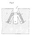
- Fig. 2 eine schaubildliche Darstellung der Rastschiene gemäß Fig. 1, in
- Fig. 3 eine abgeänderte Ausführungsform einer Rastschiene, in
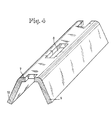
- Fig. 4 eine schaubildliche Darstellung der Rastschiene gemäß Fig. 3, in
- Fig. 5 eine wiederum abgeänderte Ausführungsform einer Rastschiene und in
- Fig. 6 eine schaubildliche Darstellung der Rastschiene gemäß Fig. 5.
- Fig. 1 shows a first embodiment of a locking rail in the inserted state, in
- Fig. 2 is a perspective view of the locking rail according to FIG. 1, in
- Fig. 3 shows a modified embodiment of a locking rail, in
- Fig. 4 is a perspective view of the locking rail according to FIG. 3, in
- Fig. 5 shows a modified embodiment of a locking rail and in
- 6 is a diagrammatic representation of the locking rail according to FIG. 5.
In den Figuren ist mit 1 jeweils die Wandung eines Möbelteiles bezeichnet, in dem zur Außenseite 3 hin ein Schlitz 2 erkennbar ist. Der Schlitz weist dabei eine Breite von etwa 1,8 bis 2 mm auf.In the figures, 1 denotes the wall of a piece of furniture in which a
Gemäß Fig. 1 ist in den Schlitz 2 eine Stegschiene 4 eingesetzt, die mit Hinterschneidungen 5 ausgerüstet ist, so daß Aufnahmeräume für die Haltebeschläge geschaffen werden, die beispielsweise als Haken ausgebildet sein können. Die Verankerung der Stegschiene 4 in dem Schlitz 2 erfolgt durch in der Zeichnung aus Übersichtlichkeitsgründen nicht dargestellte Verzahnungen, wobei auch oder zusätzlich ein entsprechendes Verkleben der Stegschiene 4 in dem Schlitz 2 erfolgen kann.1, a web rail 4 is used in the
Der Schlitz 2 wird bei der Ausführugsform gemäß Fig. 1 durch einen einfachen, über die Länge des Mö belteiles geführten Sägeschnitt erzielt.The
Bei dem in den Fig. 3 und 4 dargestellten Ausführungsbeispiel ist die Rastschiene als U-Schiene 6 ausgebildet, die einen Frontsteg 7 aufweist, in dem die Rasteröffnungen 8 ausgenommen sind. An den Frontsteg 7 schließen sich Flansche 9 und 1O an, wobei der Innenwinkel α zwischen den Flanschen 9 und 1O und dem Frontsteg 7 größer als 9O° ist, so daß sich die Flansche V-förmig nach hinten erweitern. Vorzugsweise beträgt der Winkel α 115°.In the embodiment shown in FIGS. 3 and 4, the locking rail is designed as a U-rail 6, which has a
Der Raum, um diese V-förmige U-Schiene 6 aufzunehmen, wird dadurch erzielt, daß, wie bei der Ausführungsform gemäß Fig. 1, zuerst ein Sägeschnitt über die Länge des Möbelteiles verlaufend geführt wird, der den Schlitz 2 und einen Raum 11 schafft, der zur Aufnahme der widerhakenartigen Rückteile der in die Rasteröffnungen 8 einzuhängenden Beschläge dient.The space to accommodate this V-shaped U-rail 6 is achieved in that, as in the embodiment according to FIG. 1, first a saw cut is made to run the length of the furniture part, which creates the
Durch den Schlitz 2 werden dann zwei weitere Sägeschnitte geführt, die die Räume 12 und 14 schaffen, die der Aufnahme der Flansche 1O und 9 der U-Schiene 6 dienen. Aus dieser Erläuterung ist erkennbar, daß durch den gleichen Schlitz 2 ein sich nach hinten öffnender Raum geschaffen wird, der eine sichere Festlegung der U-Schiene 6 ermöglicht. Auch hierbei können die nach außen gerichteten Seiten der Flansche 9 und 1O der U-Schiene 6 mit Verzahnungen ausgerüstet sein, die eine noch zusätzliche Festlegung bewirken, wobei auch diese U-Schiene 6 eingeklebt sein kann.Two further saw cuts are then made through the
Bei der Ausführungsform gemäß Fig. 5 wird die Rast schiene durch eine Hohlschiene 15 gebildet mit einem Mittelsteg 16, an den sich Flansche 17 und 18 anschließen, die sich, ähnlich wie bei der Ausführungsform gemäß Fig. 3, zur Rückseite hin öffnen, d.h. V-förmig gestaltet sind, aber nach vorne die Vorderkante des Mittelsteges 16 übergreifen, so daß hier Seitenteile 19 und 2O geschaffen werden. In dem Mittelsteg 16 sind die Öffnungen 8 zur Aufnahme der Beschlagelemente ausgenommen.5 is the rest rail formed by a
Die Mittellinie FM der Flansche 17 und 18 schließt mit der Mittellinie SM des Mittelsteges 16 einen Winkel β von etwa 115° ein.The center line FM of the
Der Aufnahmeraum für die Hohlschiene 15 wird dadurch erreicht, daß wiederum ein Sägeschnitt über die Länge des Möbelteiles geführt wird, der den Schlitz 2 und den Raum 11 schafft. Anschließend wird durch die Öffnung des Schlitzes 2 jeweils ein Sägeschnitt geführt, der die Aufnahmeräume für die Flansche 17 und 18 schafft. Auf diese Weise werden zwischen dem Raum 11 und den so geschaffenen beiden seitlichen Räumen Materialstutzen 21 und 22 gebildet, deren Kuppe durch zwei weitere, durch den Schlitz 2 geführte Sägeschnitte abgeschnitten werden können.The receiving space for the
Die Rastschienen 4, 6 und 15 können aus Metall oder Kunststoff bestehen.The
Das Einführen der Rastschienen in ihre entsprechenden Aufnahmeräume erfolgt vorzugsweise durch Einschieben in Längsachse der erzielten Sägeschnitte oder bei der Ausführungsform gemäß Fig. 1 durch Einpressen der Stegschiene 4 in den gebildeten Schlitz von außen, wobei dann vorzugsweise eine Festlegung der Stegschiene 4 ausschließlich durch Verkleben erfolgt.The locking rails are preferably inserted into their corresponding receiving spaces by inserting them in the longitudinal axis of the saw cuts obtained or, in the embodiment according to FIG. 1, by pressing the web rail 4 into the slot formed from the outside, in which case preferably a setting is then made the web rail 4 is made exclusively by gluing.
Claims (8)
daß der Beschlag als plattenförmiges Hakenelement ausgebildet ist und
daß die Schlitzbreite der Dicke des Beschlages entspricht.1. In furniture, walls or the like. Insertable snap-in rail with a hole pattern for hanging fittings, the snap-in rail on the visible side creates an outwardly open slot that extends over the entire length of the snap-in rail and is designed as a very narrow gap characterized in that the slot (2) is delimited on both sides by the material of the furniture or wall part (1),
that the fitting is designed as a plate-shaped hook element and
that the slot width corresponds to the thickness of the fitting.
Applications Claiming Priority (2)
| Application Number | Priority Date | Filing Date | Title |
|---|---|---|---|
| DE19863613655 DE3613655C1 (en) | 1986-04-23 | 1986-04-23 | In furniture, walls or the like. insertable locking rail and method for inserting such a locking rail |
| DE3613655 | 1986-04-23 |
Publications (2)
| Publication Number | Publication Date |
|---|---|
| EP0243767A2 true EP0243767A2 (en) | 1987-11-04 |
| EP0243767A3 EP0243767A3 (en) | 1988-03-02 |
Family
ID=6299288
Family Applications (1)
| Application Number | Title | Priority Date | Filing Date |
|---|---|---|---|
| EP87105399A Ceased EP0243767A3 (en) | 1986-04-23 | 1987-04-11 | Toothed rack suitable for furniture, walls or the like, and method for inserting such a rack |
Country Status (2)
| Country | Link |
|---|---|
| EP (1) | EP0243767A3 (en) |
| DE (1) | DE3613655C1 (en) |
Cited By (2)
| Publication number | Priority date | Publication date | Assignee | Title |
|---|---|---|---|---|
| EP3025616A1 (en) * | 2014-11-27 | 2016-06-01 | Grass GmbH & Co. KG | Wall element of a piece of furniture and piece of furniture with such a wall element |
| BE1024501B1 (en) * | 2016-08-16 | 2018-03-21 | Lothar Bvba | Profile for carrying a shelf |
Citations (6)
| Publication number | Priority date | Publication date | Assignee | Title |
|---|---|---|---|---|
| DE7725790U1 (en) * | 1900-01-01 | Omnia Moebelwerke Ernst Hilker & Co, 4930 Detmold | ||
| FR1396872A (en) * | 1964-05-29 | 1965-04-23 | Improvements to dovetail grooving machines | |
| US3306324A (en) * | 1964-08-28 | 1967-02-28 | Lillywhite Estelvin | Drawer fabricating apparatus |
| US3921347A (en) * | 1974-05-31 | 1975-11-25 | Gray Mfg Co | Partition construction |
| GB2064305A (en) * | 1979-11-07 | 1981-06-17 | Interior Systems Uk Ltd | Improvements in or relating to shelf supports for merchandise display systems |
| DE3408575A1 (en) * | 1984-03-09 | 1985-09-12 | Hermann Lüning GmbH & Co Möbelfabrik, 4840 Rheda-Wiedenbrück | Connection arrangement on upright furniture |
Family Cites Families (2)
| Publication number | Priority date | Publication date | Assignee | Title |
|---|---|---|---|---|
| EP0055538B1 (en) * | 1980-12-11 | 1987-04-15 | Anthony Charles Worrallo | Structures in which brackets are releasably secured to structural elements |
| DE3144891C2 (en) * | 1981-11-12 | 1984-06-28 | Heinz Georg Hünibach Thun Baus | Device for attaching shelves, shelves and the like. |
-
1986
- 1986-04-23 DE DE19863613655 patent/DE3613655C1/en not_active Expired
-
1987
- 1987-04-11 EP EP87105399A patent/EP0243767A3/en not_active Ceased
Patent Citations (6)
| Publication number | Priority date | Publication date | Assignee | Title |
|---|---|---|---|---|
| DE7725790U1 (en) * | 1900-01-01 | Omnia Moebelwerke Ernst Hilker & Co, 4930 Detmold | ||
| FR1396872A (en) * | 1964-05-29 | 1965-04-23 | Improvements to dovetail grooving machines | |
| US3306324A (en) * | 1964-08-28 | 1967-02-28 | Lillywhite Estelvin | Drawer fabricating apparatus |
| US3921347A (en) * | 1974-05-31 | 1975-11-25 | Gray Mfg Co | Partition construction |
| GB2064305A (en) * | 1979-11-07 | 1981-06-17 | Interior Systems Uk Ltd | Improvements in or relating to shelf supports for merchandise display systems |
| DE3408575A1 (en) * | 1984-03-09 | 1985-09-12 | Hermann Lüning GmbH & Co Möbelfabrik, 4840 Rheda-Wiedenbrück | Connection arrangement on upright furniture |
Cited By (2)
| Publication number | Priority date | Publication date | Assignee | Title |
|---|---|---|---|---|
| EP3025616A1 (en) * | 2014-11-27 | 2016-06-01 | Grass GmbH & Co. KG | Wall element of a piece of furniture and piece of furniture with such a wall element |
| BE1024501B1 (en) * | 2016-08-16 | 2018-03-21 | Lothar Bvba | Profile for carrying a shelf |
Also Published As
| Publication number | Publication date |
|---|---|
| DE3613655C1 (en) | 1987-10-29 |
| EP0243767A3 (en) | 1988-03-02 |
Similar Documents
| Publication | Publication Date | Title |
|---|---|---|
| EP1152506B1 (en) | Frame | |
| DE3214727C2 (en) | ||
| EP0641939B1 (en) | Fastening device | |
| DE2927114A1 (en) | SHELVING SYSTEM | |
| EP0961535A1 (en) | Distance piece for mouting a pcb onto an electrically conductive carrier | |
| DE1529646C3 (en) | shelf | |
| DE2819138C2 (en) | Device for adjustable fastening of an object on a wall | |
| EP0127030A2 (en) | Corner joint | |
| DE3038341A1 (en) | Expanding dowel inserted in aperture - has slot-shaped recess, with side of synthetic material to engage on screw | |
| EP0444257A1 (en) | Device for receiving a sign | |
| DE2126955A1 (en) | Fitting for joining two or more walls that are perpendicular to one another, in particular panel-shaped furniture walls | |
| DE3613655C1 (en) | In furniture, walls or the like. insertable locking rail and method for inserting such a locking rail | |
| DE69934286T2 (en) | Framework, in particular for an electrical appliance | |
| DE19508949C2 (en) | Kit for a support system | |
| EP0116013A2 (en) | Device for variable compartments for drawers | |
| DE2715830A1 (en) | FURNITURE ITEMS | |
| DE3203652A1 (en) | Frame profile with detachable facings | |
| EP0064754B1 (en) | Holding device for prospectuses and the like flat material | |
| AT394303B (en) | DRAWER | |
| DE3521014A1 (en) | Holder for number plate | |
| DE2553509C2 (en) | Device for connecting a cover profile to a frame profile | |
| DE60003286T2 (en) | DEVICE FOR A HOLDER | |
| DE8420175U1 (en) | HOUSEHOLD APPLIANCE WITH A PANEL BODY | |
| DE3433438C2 (en) | ||
| AT4995U1 (en) | CONNECTING ELEMENT FOR PARTITIONS FOR PARTICULATING A DRAWER |
Legal Events
| Date | Code | Title | Description |
|---|---|---|---|
| PUAI | Public reference made under article 153(3) epc to a published international application that has entered the european phase |
Free format text: ORIGINAL CODE: 0009012 |
|
| AK | Designated contracting states |
Kind code of ref document: A2 Designated state(s): AT BE CH DE ES FR GB IT LI NL SE |
|
| PUAL | Search report despatched |
Free format text: ORIGINAL CODE: 0009013 |
|
| AK | Designated contracting states |
Kind code of ref document: A3 Designated state(s): AT BE CH DE ES FR GB IT LI NL SE |
|
| 17P | Request for examination filed |
Effective date: 19880121 |
|
| 17Q | First examination report despatched |
Effective date: 19891019 |
|
| STAA | Information on the status of an ep patent application or granted ep patent |
Free format text: STATUS: THE APPLICATION HAS BEEN REFUSED |
|
| 18R | Application refused |
Effective date: 19901115 |
|
| RIN1 | Information on inventor provided before grant (corrected) |
Inventor name: HETTICH, VOLKER, DIPL.-ING. Inventor name: HUELS, KARL |